University Portfolio: System Analysis and Design, SBM4201 Assessment

Verified

Added on  2023/01/16

|16
|1231
|32
Project
AI Summary
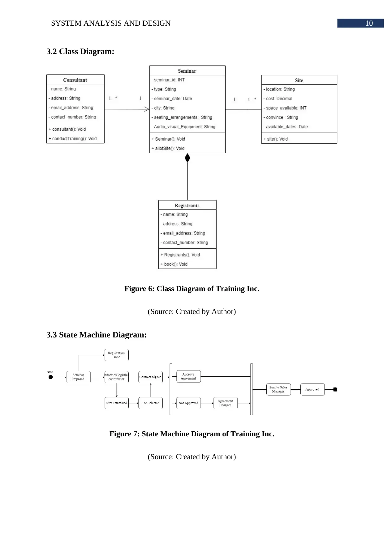
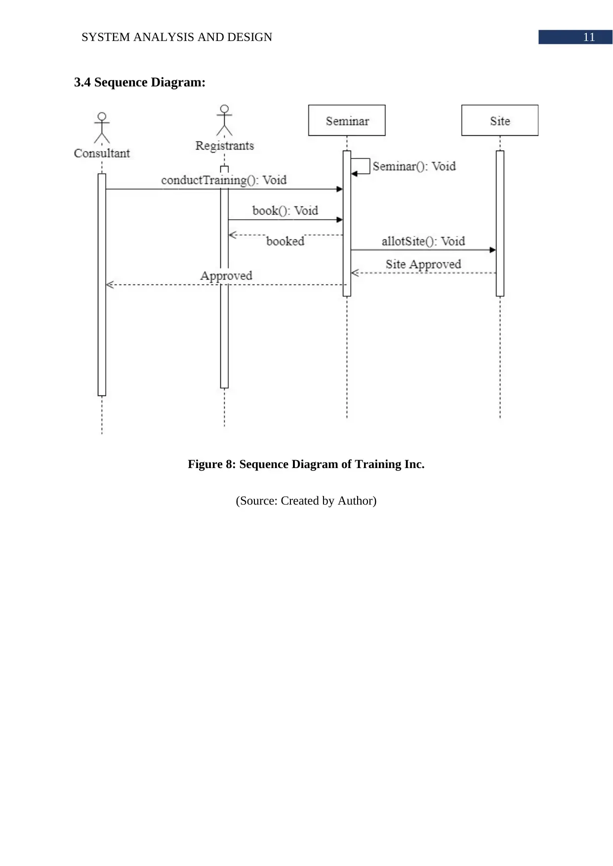
This document presents a comprehensive System Analysis and Design portfolio, covering various aspects of the system development lifecycle. It begins with a Work Breakdown Structure and Critical Path analysis, followed by a detailed examination of a Hospital Management System, including entities, attributes, use cases, and a use case diagram. The portfolio then progresses to class diagrams, ER diagrams, state machine diagrams, sequence diagrams, activity diagrams, and system architecture diagrams, providing a visual representation of system components and interactions. It also includes user interface designs and concludes with a discussion on testing and deployment activities, including black box testing and cloud deployment strategies. The document is a valuable resource for students studying system analysis and design, offering practical examples and insights into the development process. It also includes a bibliography of relevant sources.
Document Page
Running head: SYSTEM ANALYSIS AND DESIGN
System Analysis and Design
Name of the Student
Name of the University
Author’s note:
tabler-icon-diamond-filled.svg

Paraphrase This Document

Need a fresh take? Get an instant paraphrase of this document with our AI Paraphraser
Document Page
1SYSTEM ANALYSIS AND DESIGN
Table of Contents
Portfolio 1:.................................................................................................................................2
Question 1: Work Breakdown Structure and Critical Path....................................................2
1.1 Work Breakdown Structure..........................................................................................2
1.2 Critical Path..................................................................................................................3
Question 2: Hospital Management System............................................................................3
2.1 Entities and Attributes:.................................................................................................3
2.2 Use Case and Actors Identification:.............................................................................5
2.3 Use case diagram:........................................................................................................7
Portfolio 2...................................................................................................................................8
Question 1:.............................................................................................................................8
2.1 Class diagram...............................................................................................................8
Portfolio 3:.................................................................................................................................9
3.1 ER Diagram:.....................................................................................................................9
3.2 Class Diagram:...............................................................................................................10
3.3 State Machine Diagram:.................................................................................................10
3.4 Sequence Diagram:........................................................................................................11
Portfolio 4:...............................................................................................................................12
4.1 Activity Diagram:...........................................................................................................12
4.2 System Architecture Diagram:.......................................................................................12
4.3 User Interface:................................................................................................................13
Portfolio 5:...............................................................................................................................13
5.1 Testing and Deployment Activities:...............................................................................13
5.1.1 Testing:....................................................................................................................13
5.1.2 Deployment:............................................................................................................14
Bibliography:............................................................................................................................15
Document Page
2SYSTEM ANALYSIS AND DESIGN
Portfolio 1:
Question 1: Work Breakdown Structure and Critical Path
1.1 Work Breakdown Structure
Task Name Duration Start Finish Predecessors
Portfolio1Ganttchart 45 days Tue 30-04-19 Mon 01-07-19
1.0 System Design 5 days Tue 30-04-19 Mon 06-05-19
2.0 Design Phase 14 days Tue 07-05-19 Fri 24-05-19
2.1 Subsystem A 5 days Tue 07-05-19 Mon 13-05-19
2.2 Subsystem B 4 days Tue 14-05-19 Fri 17-05-19 3
2.3 Subsystem C 5 days Mon 20-05-
19 Fri 24-05-19 4
3.0 Programming 22 days Mon 27-05-
19 Tue 25-06-19
3.1 Program A 9 days Mon 27-05-
19 Thu 06-06-19 5
3.2 Program B 5 days Fri 07-06-19 Thu 13-06-19 7
3.3 Program C 8 days Fri 14-06-19 Tue 25-06-19 8
4.0 Testing 4 days Wed 26-06-
19 Mon 01-07-19 9
Figure 1: Work Breakdown Structure
(Source: Created by Author)
Document Page
3SYSTEM ANALYSIS AND DESIGN
1.2 Critical Path
ID Task
Mode
Task Name Duration Start Finish
0 Portfolio1Ganttchart45 days Tue
30-04-19
Mon
01-07-19
1 1.0 System Design 5 days Tue 30-04-19 Mon 06-05-19
2 2.0 Design Phase 14 days Tue 07-05-19 Fri 24-05-19
3 2.1 Subsystem A5 days Tue 07-05-19 Mon 13-05-19
4 2.2 Subsystem B4 days Tue 14-05-19 Fri 17-05-19
5 2.3 Subsystem C5 days Mon 20-05-19 Fri 24-05-19
6 3.0 Programming 22 days Mon 27-05-19Tue 25-06-19
7 3.1 Program A 9 days Mon 27-05-19 Thu 06-06-19
8 3.2 Program B 5 days Fri 07-06-19 Thu 13-06-19
9 3.3 Program C 8 days Fri 14-06-19 Tue 25-06-19
10 4.0 Testing 4 days Wed 26-06-19Mon 01-07-19
S T M F T S W S T M F T S W S T M F
22 Apr '19 06 May '19 20 May '19 03 Jun '19 17 Jun '19 01 Jul '19
Figure 2: Critical Path
(Source: Created by Author)
Question 2: Hospital Management System
2.1 Entities and Attributes:
Entities Actors
Receptionist Receptionist_id
Name
Address
Email_addess
Contact
Salary
Join_date
Patient Patient_id
Name
Address
tabler-icon-diamond-filled.svg

Paraphrase This Document

Need a fresh take? Get an instant paraphrase of this document with our AI Paraphraser
Document Page
4SYSTEM ANALYSIS AND DESIGN
Email_addess
Contact
Contact_Person
Contact_Person_Phone_Number
Doctor Doctor_id
Name
Address
Email_addess
Contact
Type
Appointment Appointment_id
Appointment_date
Appointment_time
Doctor_id
Patient_id
Illness_overview
Admission Admission_id
Admission_date
Bed_number
Patient_id
Illness
Expected_Release_Date
Service_Details
Bed Bed_number
Ward
Document Page
5SYSTEM ANALYSIS AND DESIGN
Charge
Status
Payment Payment_id
Patient_id
Payment_amount
tax
discount
Total_payment
Payment_method
2.2 Use Case and Actors Identification:
The list of use case are as following.
i. Schedule Admissions
ii. Patient registration
iii. Schedule Appointments
iv. Admit Patients
v. Collect Patient Data
vi. Allot Bed
vii. Receive Payments
viii. Keep Records
ix. Distribute Reports
x. Provide Receipts
xi. Insurance Claims
The list of the actors are as following.
Document Page
6SYSTEM ANALYSIS AND DESIGN
i. Receptionist
ii. Patient
iii. Doctors
tabler-icon-diamond-filled.svg

Paraphrase This Document

Need a fresh take? Get an instant paraphrase of this document with our AI Paraphraser
Document Page
7SYSTEM ANALYSIS AND DESIGN
2.3 Use case diagram:
Figure 3: Use Case Diagram of Hospital Management System
(Source: Created by Author)
Document Page
8SYSTEM ANALYSIS AND DESIGN
Portfolio 2
Question 1:
2.1 Class diagram
Figure 4: Class Diagram of Software Protection and Licensing
(Source: Created by Author)
Document Page
9SYSTEM ANALYSIS AND DESIGN
Portfolio 3:
3.1 ER Diagram:
Figure 5: Entity Relationship Diagram of Training Inc.
(Source: Created by Author)
tabler-icon-diamond-filled.svg

Paraphrase This Document

Need a fresh take? Get an instant paraphrase of this document with our AI Paraphraser
Document Page
10SYSTEM ANALYSIS AND DESIGN
3.2 Class Diagram:
Figure 6: Class Diagram of Training Inc.
(Source: Created by Author)
3.3 State Machine Diagram:
Figure 7: State Machine Diagram of Training Inc.
(Source: Created by Author)
Document Page
11SYSTEM ANALYSIS AND DESIGN
3.4 Sequence Diagram:
Figure 8: Sequence Diagram of Training Inc.
(Source: Created by Author)
chevron_up_icon
1 out of 16
circle_padding
hide_on_mobile
zoom_out_icon
[object Object]