Comprehensive System Analysis of World Tours Online Booking System
VerifiedAdded on 2021/02/18
|13
|1464
|162
Report
AI Summary
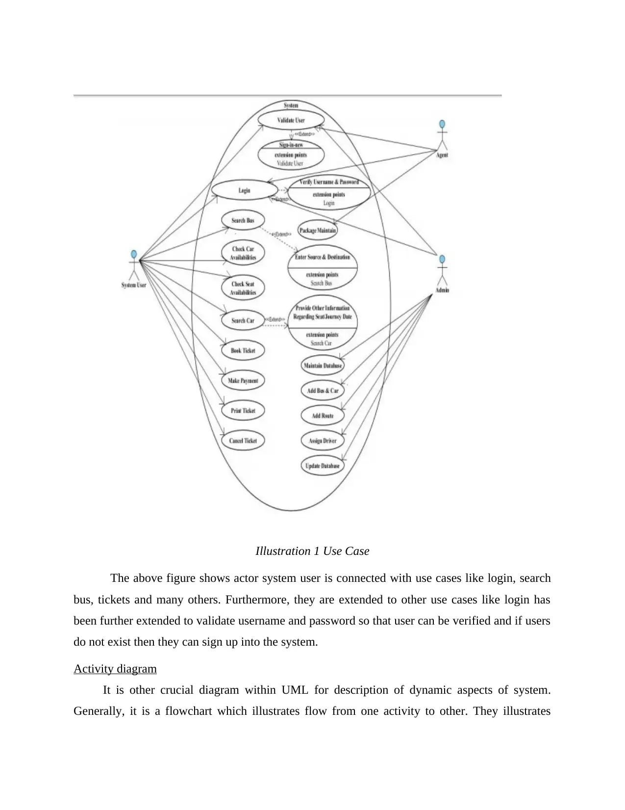
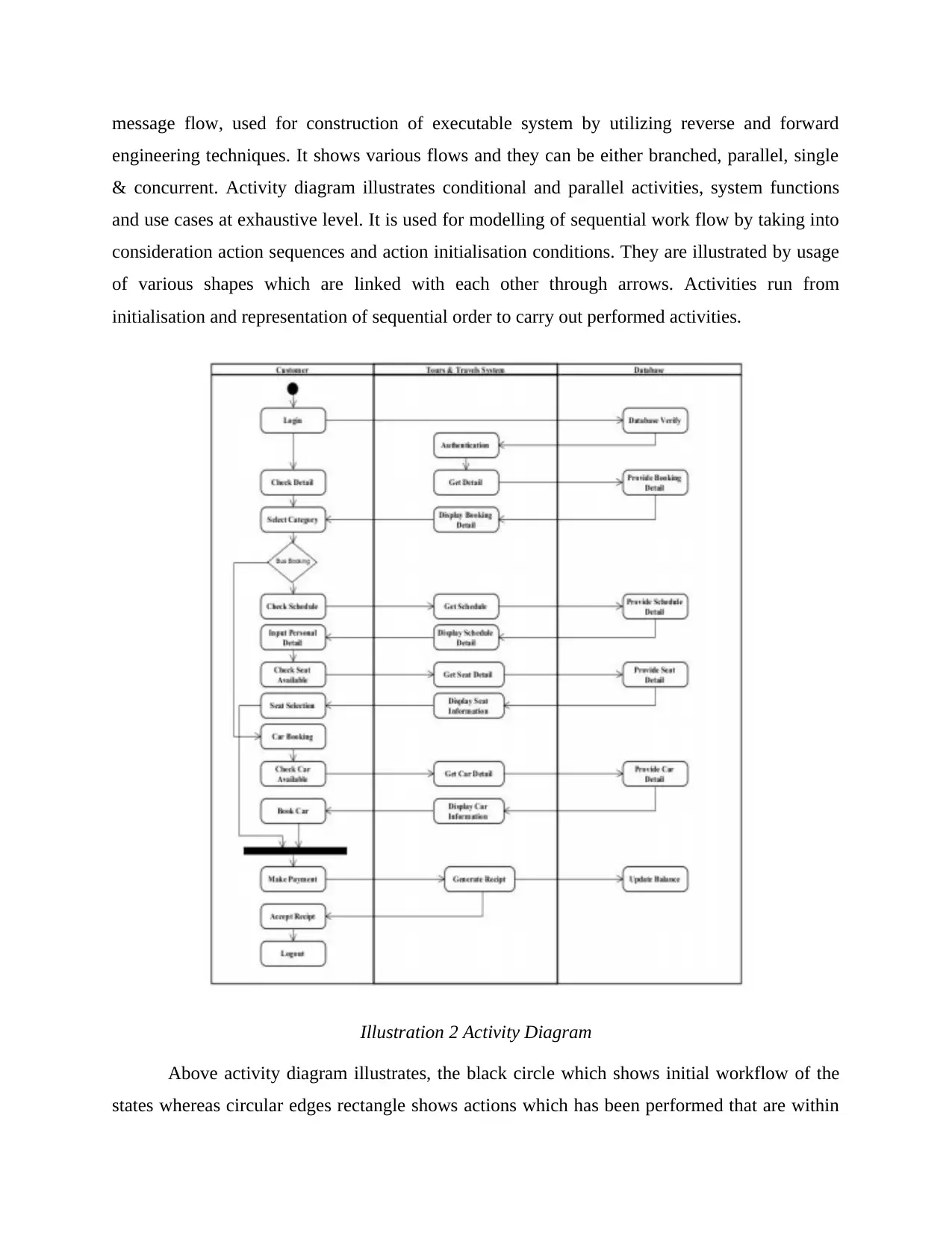
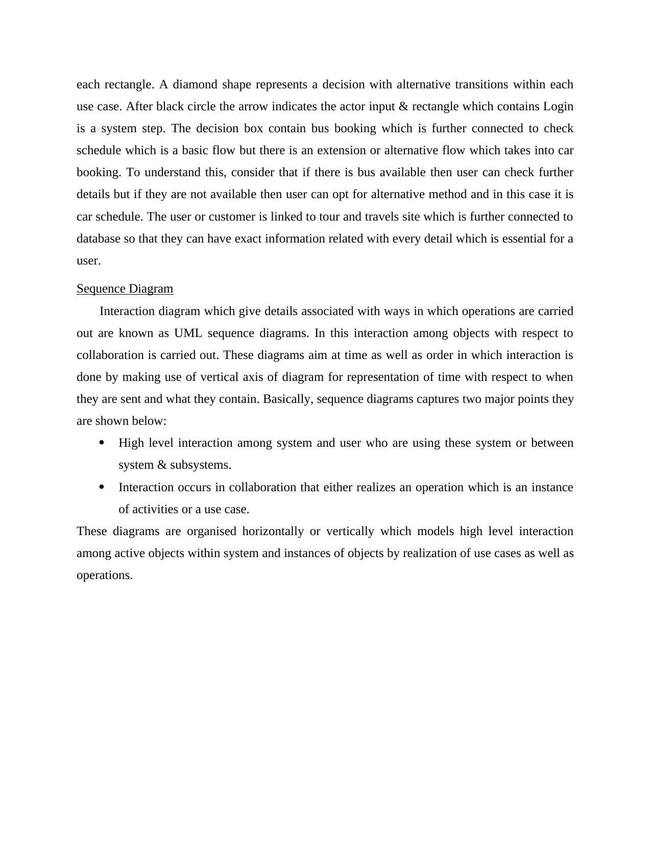
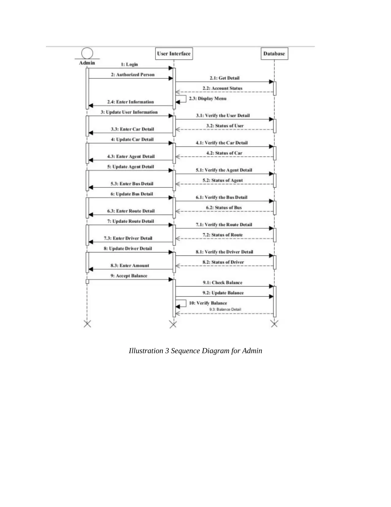
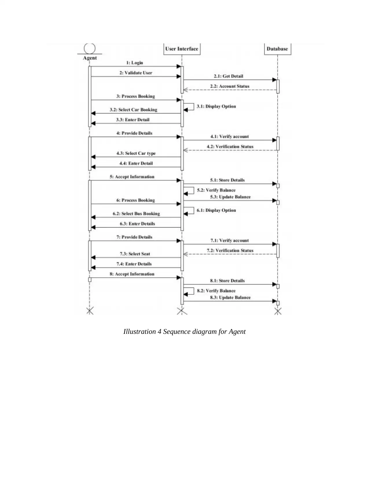
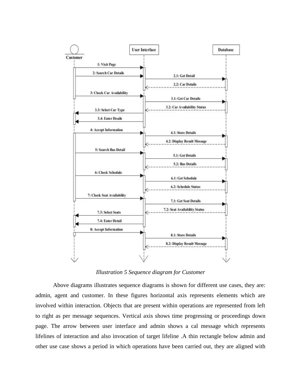
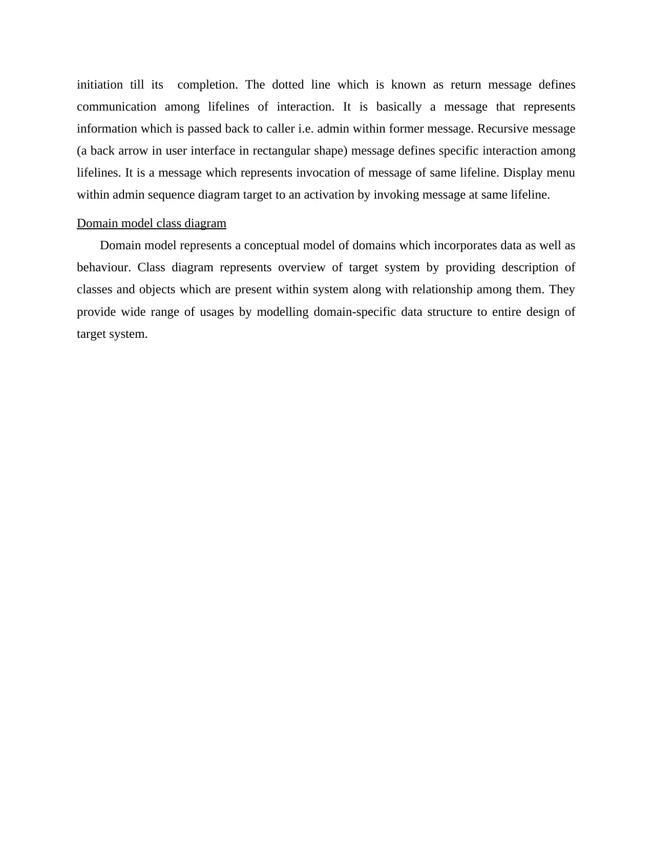
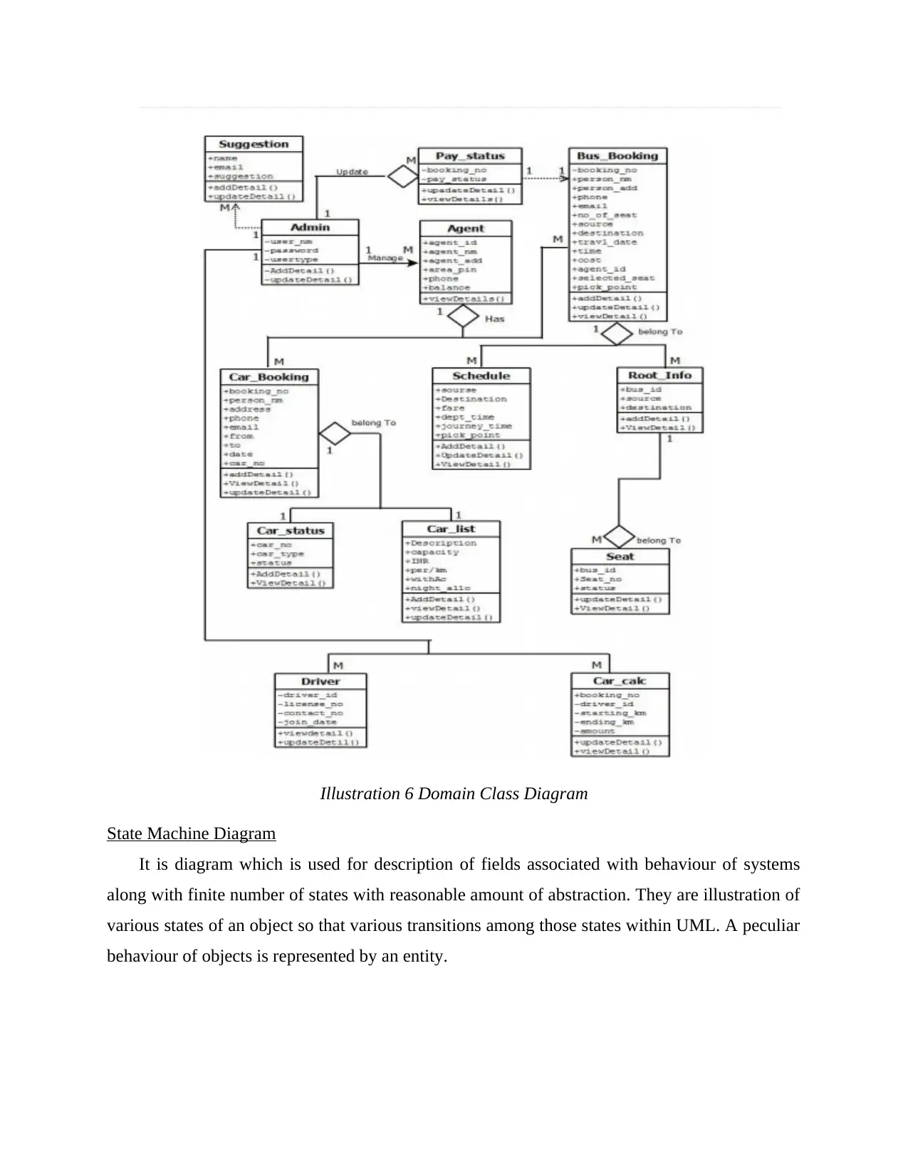
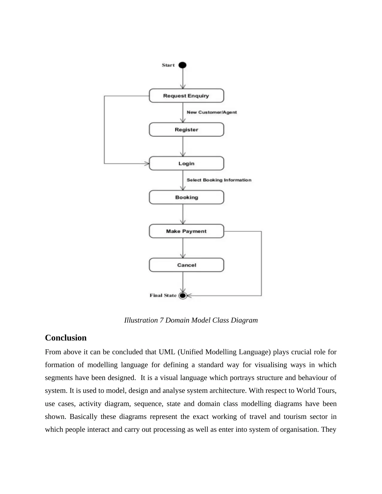
This report presents a comprehensive system analysis of World Tours, an online company facilitating tour bookings and payments. The analysis employs Unified Modeling Language (UML) diagrams to illustrate various aspects of the system. It begins with an introduction to system analysis, defining its purpose and scope. The core of the report comprises several UML diagrams, including a use case diagram depicting interactions between actors (system user, admin, and agent) and system functions like login, search, and booking. An activity diagram illustrates the workflow of various processes, such as bus and car booking, with conditional flows and decision points. Sequence diagrams are provided for admin, agent and customer interactions, showing the chronological order of message exchanges between objects. A domain model class diagram represents the conceptual model of the system's data and behavior, outlining classes and their relationships. Finally, a state machine diagram is included, describing the object's behavior and transitions. The report concludes by summarizing the importance of UML in system design and its application within the context of World Tours.

System Analysis
Paraphrase This Document
Need a fresh take? Get an instant paraphrase of this document with our AI Paraphraser

Table of Contents
Introduction......................................................................................................................................3
Use case Diagram...................................................................................................................3
Activity diagram.....................................................................................................................4
Sequence Diagram..................................................................................................................6
Domain model class diagram...............................................................................................10
State Machine Diagram........................................................................................................11
Conclusion.....................................................................................................................................12

Introduction
System analysis refers to process of collection and interpretation of facts, identification of
problems and decomposition of systems within their components. The major purpose of system
analysis is to study system & their parts for identification of objectives. Apart from this, problem
solving techniques improvises system as well as make sure that all components are working in
appropriate manner. This report is based on World Tours which is an online company that deals
with providing their customers with a service of facility for booking and pay for tours via online
method. This contains use cases, activity, sequence, domain model class, state machine
diagrams. Apart from this user interface is provided.
Use case Diagram
A graphic depiction related with communication among various elements of system.
Basically, it is a methodology which is being utilised for identification, clarification and
organisation of system needs. System is something which is operated or developed like mail
related with details of tour. Unified modelling language (UML) has been used which is a
standard notation for modelling of systems and objects. This comprises of overall planning
needs, validation of hardware design, their testing and software debugging with respect to
service oriented task.
In context of World Tours, three use cases have been identified. Actors are the one who
interacts with system function and plays crucial role within business. In this case actors are:
system user, admin and user. Use cases are system function that can be manual or automated
which are associated with actors. Use cases here are validate user, sign-in, login, verification of
username & password and many others are depicted below within a diagram. The participation
of actors within use case is depicted by linking actor to them by usage of solid line or link. This
shows that they both interact with one another by making use of messages. Extend in this
diagram like login extends verify username & password shows behaviour which is depicted by
base use case “Login”. Dotted line with arrowhead points towards base use case along with child
use case which is associated at base of arrow.
⊘ This is a preview!⊘
Do you want full access?
Subscribe today to unlock all pages.

Trusted by 1+ million students worldwide

Illustration 1 Use Case
The above figure shows actor system user is connected with use cases like login, search
bus, tickets and many others. Furthermore, they are extended to other use cases like login has
been further extended to validate username and password so that user can be verified and if users
do not exist then they can sign up into the system.
Activity diagram
It is other crucial diagram within UML for description of dynamic aspects of system.
Generally, it is a flowchart which illustrates flow from one activity to other. They illustrates
Paraphrase This Document
Need a fresh take? Get an instant paraphrase of this document with our AI Paraphraser

message flow, used for construction of executable system by utilizing reverse and forward
engineering techniques. It shows various flows and they can be either branched, parallel, single
& concurrent. Activity diagram illustrates conditional and parallel activities, system functions
and use cases at exhaustive level. It is used for modelling of sequential work flow by taking into
consideration action sequences and action initialisation conditions. They are illustrated by usage
of various shapes which are linked with each other through arrows. Activities run from
initialisation and representation of sequential order to carry out performed activities.
Illustration 2 Activity Diagram
Above activity diagram illustrates, the black circle which shows initial workflow of the
states whereas circular edges rectangle shows actions which has been performed that are within

each rectangle. A diamond shape represents a decision with alternative transitions within each
use case. After black circle the arrow indicates the actor input & rectangle which contains Login
is a system step. The decision box contain bus booking which is further connected to check
schedule which is a basic flow but there is an extension or alternative flow which takes into car
booking. To understand this, consider that if there is bus available then user can check further
details but if they are not available then user can opt for alternative method and in this case it is
car schedule. The user or customer is linked to tour and travels site which is further connected to
database so that they can have exact information related with every detail which is essential for a
user.
Sequence Diagram
Interaction diagram which give details associated with ways in which operations are carried
out are known as UML sequence diagrams. In this interaction among objects with respect to
collaboration is carried out. These diagrams aim at time as well as order in which interaction is
done by making use of vertical axis of diagram for representation of time with respect to when
they are sent and what they contain. Basically, sequence diagrams captures two major points they
are shown below:
High level interaction among system and user who are using these system or between
system & subsystems.
Interaction occurs in collaboration that either realizes an operation which is an instance
of activities or a use case.
These diagrams are organised horizontally or vertically which models high level interaction
among active objects within system and instances of objects by realization of use cases as well as
operations.
⊘ This is a preview!⊘
Do you want full access?
Subscribe today to unlock all pages.

Trusted by 1+ million students worldwide

Illustration 3 Sequence Diagram for Admin
Paraphrase This Document
Need a fresh take? Get an instant paraphrase of this document with our AI Paraphraser

Illustration 4 Sequence diagram for Agent

Illustration 5 Sequence diagram for Customer
Above diagrams illustrates sequence diagrams is shown for different use cases, they are:
admin, agent and customer. In these figures horizontal axis represents elements which are
involved within interaction. Objects that are present within operations are represented from left
to right as per message sequences. Vertical axis shows time progressing or proceedings down
page. The arrow between user interface and admin shows a cal message which represents
lifelines of interaction and also invocation of target lifeline .A thin rectangle below admin and
other use case shows a period in which operations have been carried out, they are aligned with
⊘ This is a preview!⊘
Do you want full access?
Subscribe today to unlock all pages.

Trusted by 1+ million students worldwide

initiation till its completion. The dotted line which is known as return message defines
communication among lifelines of interaction. It is basically a message that represents
information which is passed back to caller i.e. admin within former message. Recursive message
(a back arrow in user interface in rectangular shape) message defines specific interaction among
lifelines. It is a message which represents invocation of message of same lifeline. Display menu
within admin sequence diagram target to an activation by invoking message at same lifeline.
Domain model class diagram
Domain model represents a conceptual model of domains which incorporates data as well as
behaviour. Class diagram represents overview of target system by providing description of
classes and objects which are present within system along with relationship among them. They
provide wide range of usages by modelling domain-specific data structure to entire design of
target system.
Paraphrase This Document
Need a fresh take? Get an instant paraphrase of this document with our AI Paraphraser

Illustration 6 Domain Class Diagram
State Machine Diagram
It is diagram which is used for description of fields associated with behaviour of systems
along with finite number of states with reasonable amount of abstraction. They are illustration of
various states of an object so that various transitions among those states within UML. A peculiar
behaviour of objects is represented by an entity.

Illustration 7 Domain Model Class Diagram
Conclusion
From above it can be concluded that UML (Unified Modelling Language) plays crucial role for
formation of modelling language for defining a standard way for visualising ways in which
segments have been designed. It is a visual language which portrays structure and behaviour of
system. It is used to model, design and analyse system architecture. With respect to World Tours,
use cases, activity diagram, sequence, state and domain class modelling diagrams have been
shown. Basically these diagrams represent the exact working of travel and tourism sector in
which people interact and carry out processing as well as enter into system of organisation. They
⊘ This is a preview!⊘
Do you want full access?
Subscribe today to unlock all pages.

Trusted by 1+ million students worldwide
1 out of 13
Related Documents

Your All-in-One AI-Powered Toolkit for Academic Success.
+13062052269
info@desklib.com
Available 24*7 on WhatsApp / Email
Unlock your academic potential
Copyright © 2020–2025 A2Z Services. All Rights Reserved. Developed and managed by ZUCOL.