ICT103 System Analysis and Design: UML Diagrams for IT Solutions

Verified

Added on  2023/04/25

|17
|2232
|173
Report
AI Summary
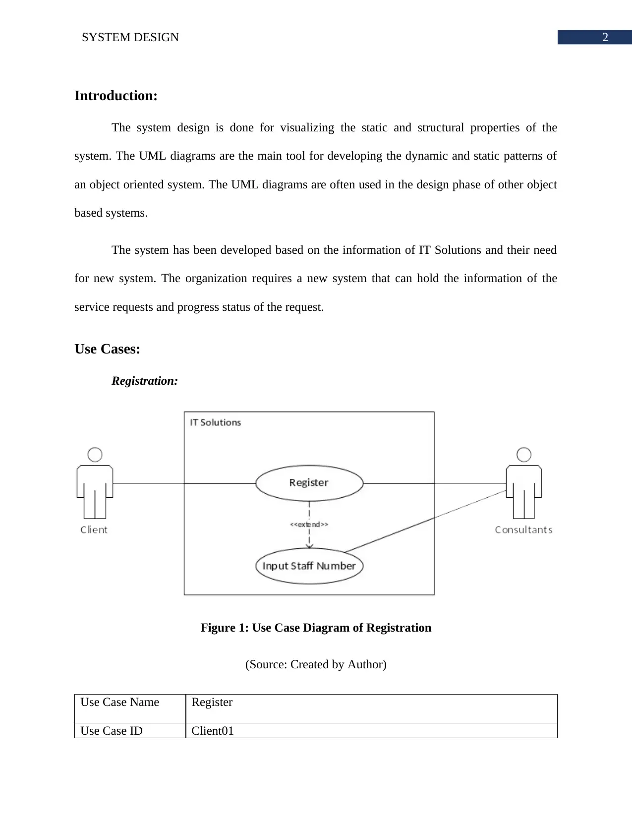
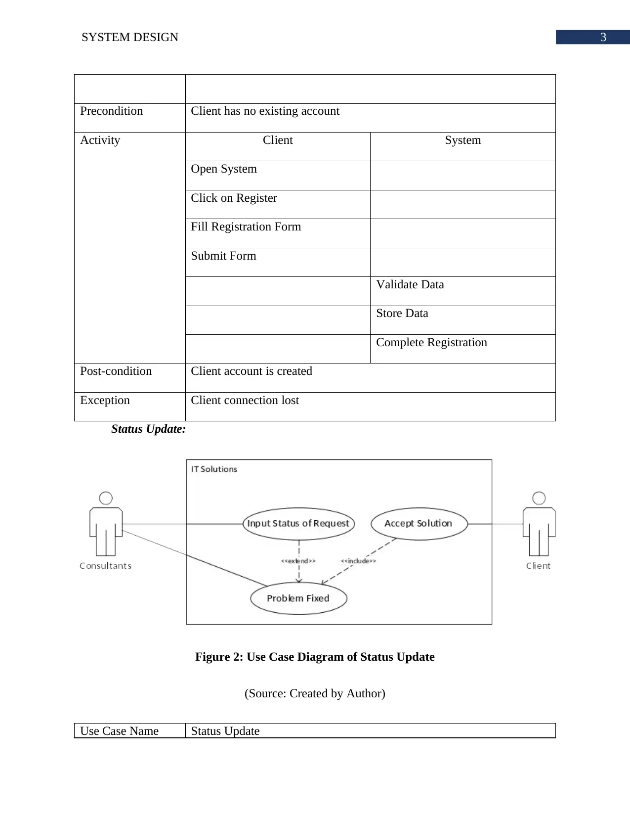
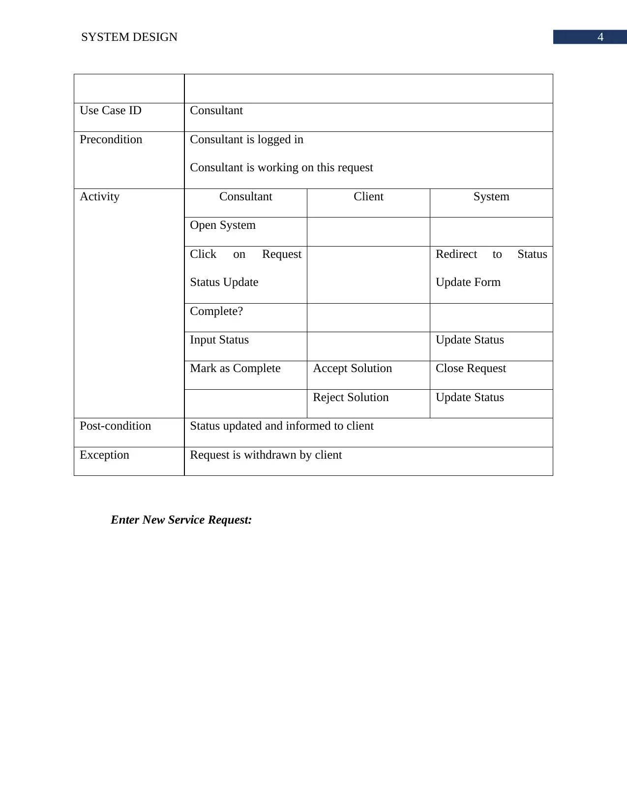
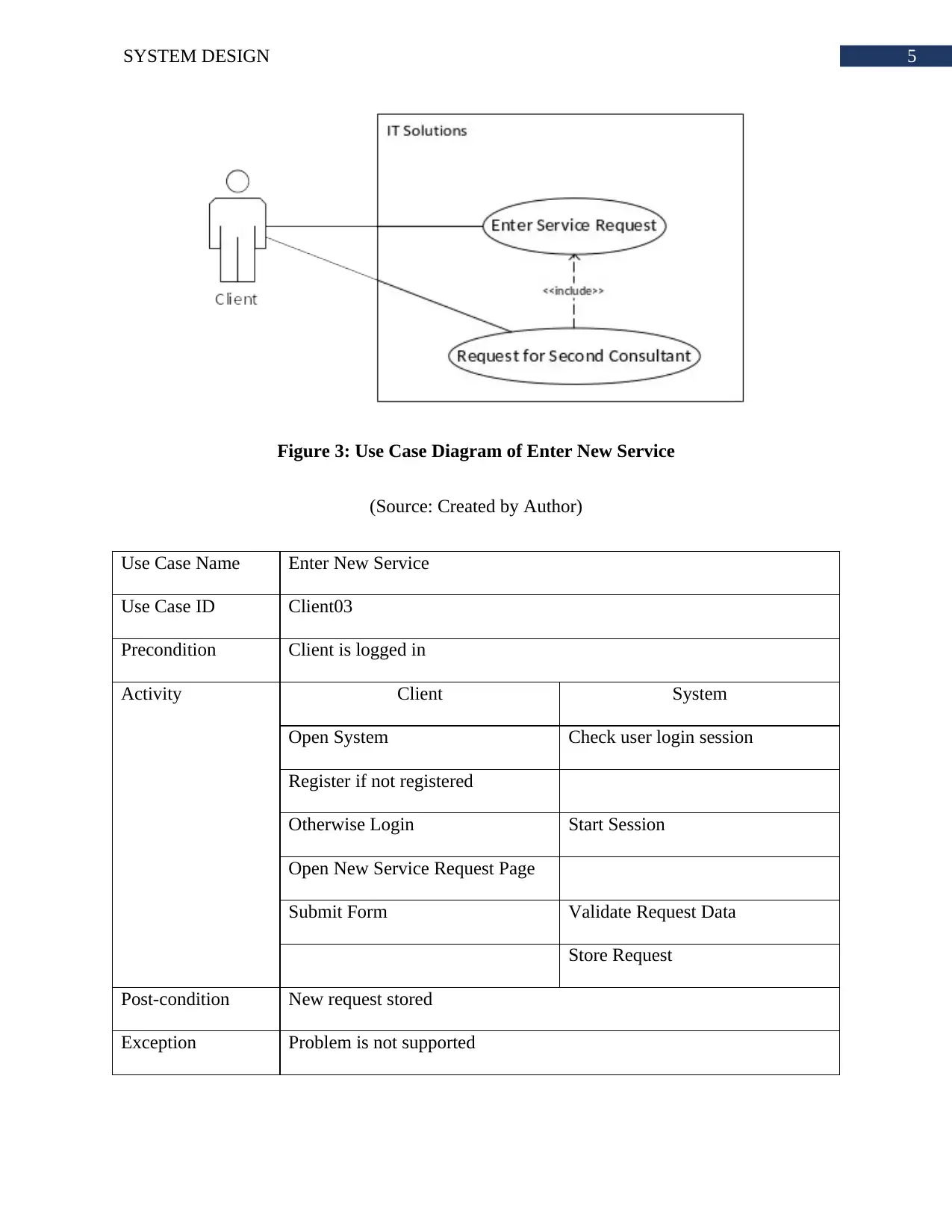
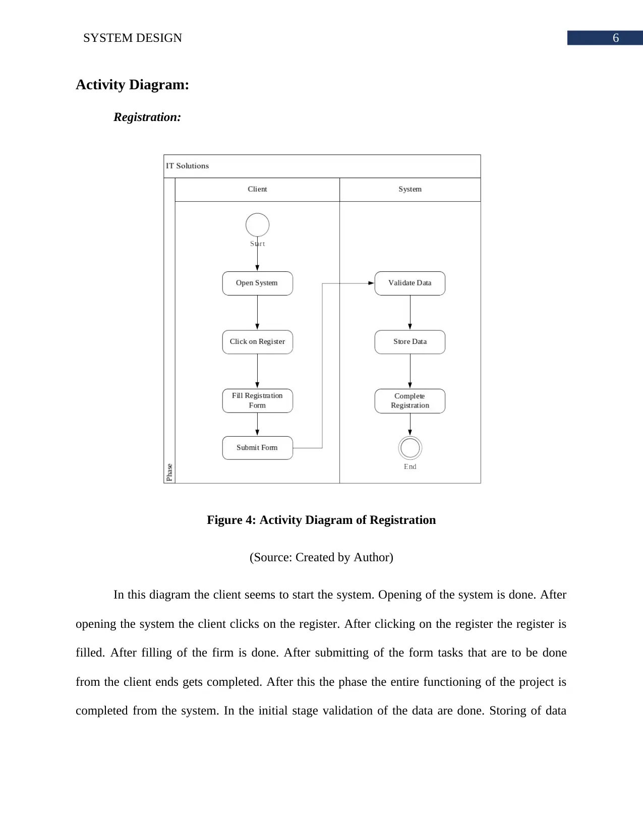
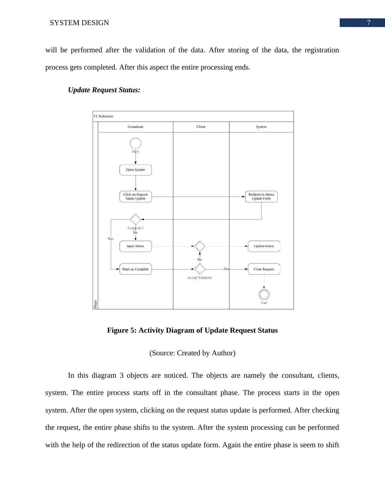
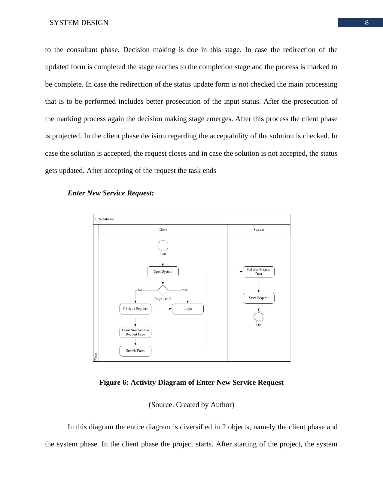
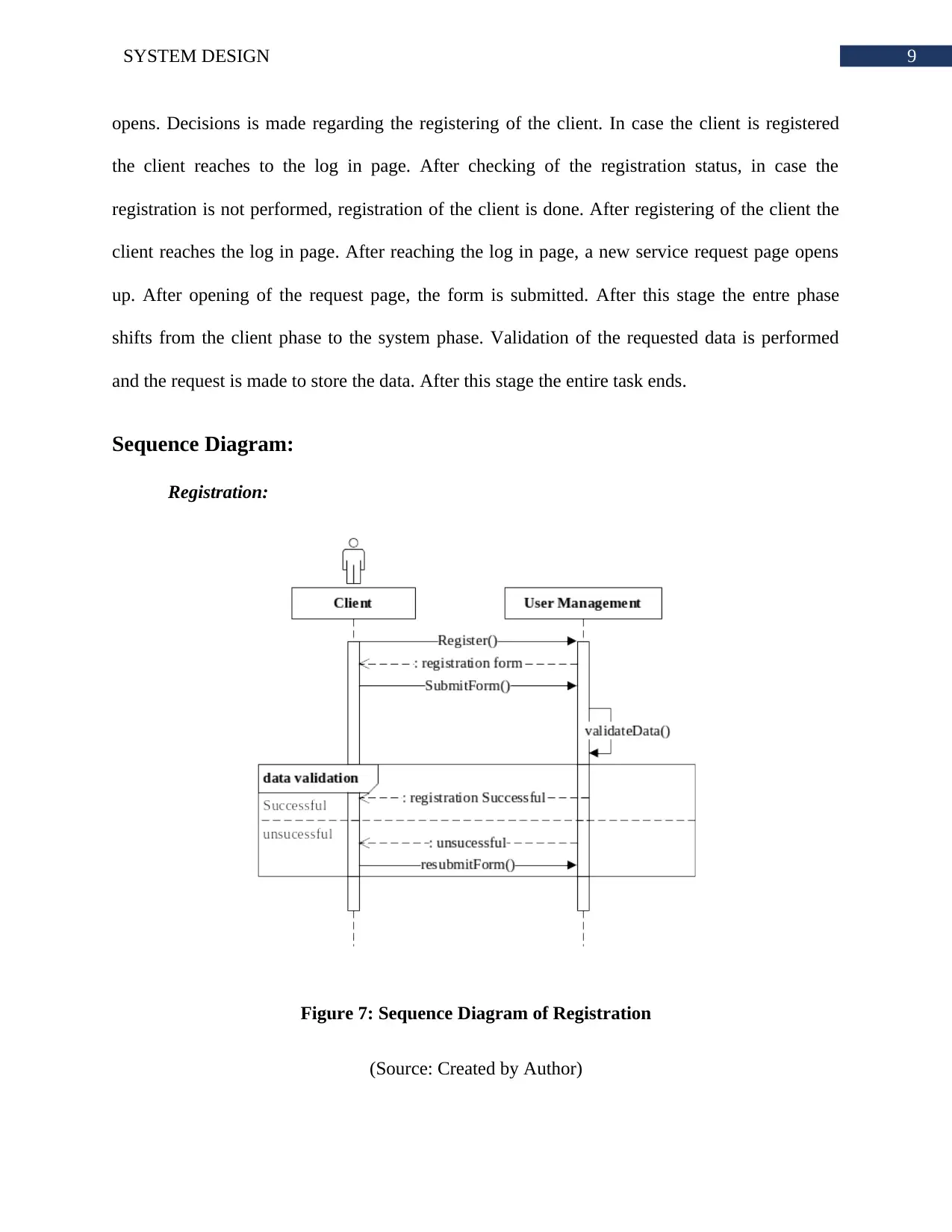
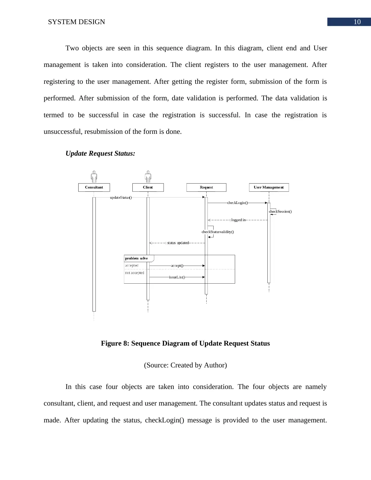
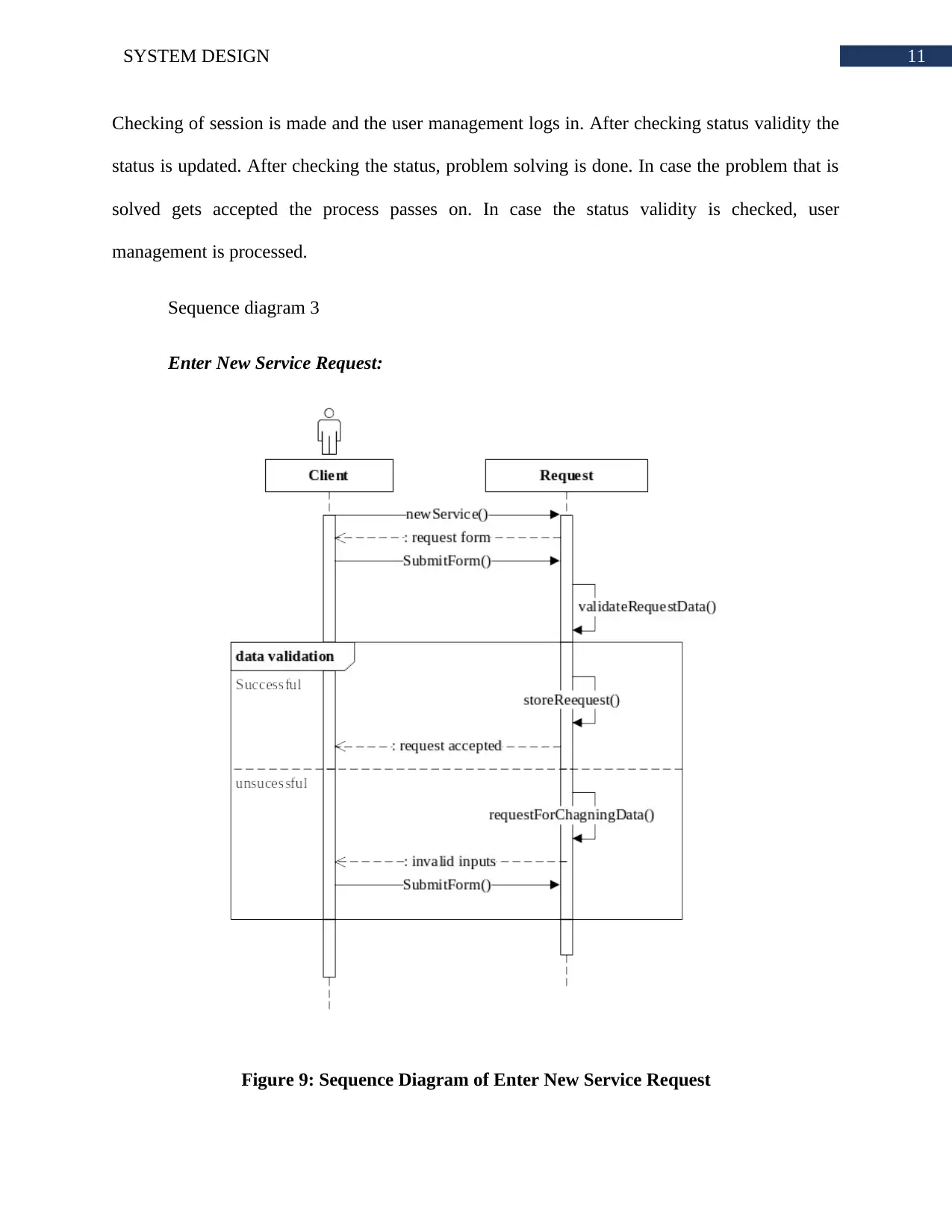
This report provides a detailed system design for IT Solutions, a small IT service provider, using UML diagrams. It includes use case diagrams for registration, status updates, and new service requests, along with corresponding activity and sequence diagrams illustrating the processes involved. A domain model class diagram outlines the structural relationships between clients, user management, requests, and consultants. Furthermore, a state machine diagram describes the various states within the system, from request submission to resolution. The report concludes with a user interface design and emphasizes the system's capability to provide an effective and validated solution. Desklib offers a wealth of similar documents and study resources for students.
Document Page
Running head: SYSTEM DESIGN
System Design of IT Solutions
Name of the Student
Name of the University
Author’s note:
tabler-icon-diamond-filled.svg

Paraphrase This Document

Need a fresh take? Get an instant paraphrase of this document with our AI Paraphraser
Document Page
1SYSTEM DESIGN
Table of Contents
Introduction:....................................................................................................................................2
Use Cases:........................................................................................................................................2
Activity Diagram:............................................................................................................................5
Sequence Diagram:..........................................................................................................................9
Domain Model Class Diagram:.....................................................................................................12
State Machine Diagram:................................................................................................................13
User Interface:...............................................................................................................................14
Conclusion:....................................................................................................................................14
Bibliography:.................................................................................................................................15
Document Page
2SYSTEM DESIGN
Introduction:
The system design is done for visualizing the static and structural properties of the
system. The UML diagrams are the main tool for developing the dynamic and static patterns of
an object oriented system. The UML diagrams are often used in the design phase of other object
based systems.
The system has been developed based on the information of IT Solutions and their need
for new system. The organization requires a new system that can hold the information of the
service requests and progress status of the request.
Use Cases:
Registration:
Figure 1: Use Case Diagram of Registration
(Source: Created by Author)
Use Case Name Register
Use Case ID Client01
Document Page
3SYSTEM DESIGN
Precondition Client has no existing account
Activity Client System
Open System
Click on Register
Fill Registration Form
Submit Form
Validate Data
Store Data
Complete Registration
Post-condition Client account is created
Exception Client connection lost
Status Update:
Figure 2: Use Case Diagram of Status Update
(Source: Created by Author)
Use Case Name Status Update
tabler-icon-diamond-filled.svg

Paraphrase This Document

Need a fresh take? Get an instant paraphrase of this document with our AI Paraphraser
Document Page
4SYSTEM DESIGN
Use Case ID Consultant
Precondition Consultant is logged in
Consultant is working on this request
Activity Consultant Client System
Open System
Click on Request
Status Update
Redirect to Status
Update Form
Complete?
Input Status Update Status
Mark as Complete Accept Solution Close Request
Reject Solution Update Status
Post-condition Status updated and informed to client
Exception Request is withdrawn by client
Enter New Service Request:
Document Page
5SYSTEM DESIGN
Figure 3: Use Case Diagram of Enter New Service
(Source: Created by Author)
Use Case Name Enter New Service
Use Case ID Client03
Precondition Client is logged in
Activity Client System
Open System Check user login session
Register if not registered
Otherwise Login Start Session
Open New Service Request Page
Submit Form Validate Request Data
Store Request
Post-condition New request stored
Exception Problem is not supported
Document Page
6SYSTEM DESIGN
Activity Diagram:
Registration:
Figure 4: Activity Diagram of Registration
(Source: Created by Author)
In this diagram the client seems to start the system. Opening of the system is done. After
opening the system the client clicks on the register. After clicking on the register the register is
filled. After filling of the firm is done. After submitting of the form tasks that are to be done
from the client ends gets completed. After this the phase the entire functioning of the project is
completed from the system. In the initial stage validation of the data are done. Storing of data
tabler-icon-diamond-filled.svg

Paraphrase This Document

Need a fresh take? Get an instant paraphrase of this document with our AI Paraphraser
Document Page
7SYSTEM DESIGN
will be performed after the validation of the data. After storing of the data, the registration
process gets completed. After this aspect the entire processing ends.
Update Request Status:
Figure 5: Activity Diagram of Update Request Status
(Source: Created by Author)
In this diagram 3 objects are noticed. The objects are namely the consultant, clients,
system. The entire process starts off in the consultant phase. The process starts in the open
system. After the open system, clicking on the request status update is performed. After checking
the request, the entire phase shifts to the system. After the system processing can be performed
with the help of the redirection of the status update form. Again the entire phase is seem to shift
Document Page
8SYSTEM DESIGN
to the consultant phase. Decision making is doe in this stage. In case the redirection of the
updated form is completed the stage reaches to the completion stage and the process is marked to
be complete. In case the redirection of the status update form is not checked the main processing
that is to be performed includes better prosecution of the input status. After the prosecution of
the marking process again the decision making stage emerges. After this process the client phase
is projected. In the client phase decision regarding the acceptability of the solution is checked. In
case the solution is accepted, the request closes and in case the solution is not accepted, the status
gets updated. After accepting of the request the task ends
Enter New Service Request:
Figure 6: Activity Diagram of Enter New Service Request
(Source: Created by Author)
In this diagram the entire diagram is diversified in 2 objects, namely the client phase and
the system phase. In the client phase the project starts. After starting of the project, the system
Document Page
9SYSTEM DESIGN
opens. Decisions is made regarding the registering of the client. In case the client is registered
the client reaches to the log in page. After checking of the registration status, in case the
registration is not performed, registration of the client is done. After registering of the client the
client reaches the log in page. After reaching the log in page, a new service request page opens
up. After opening of the request page, the form is submitted. After this stage the entre phase
shifts from the client phase to the system phase. Validation of the requested data is performed
and the request is made to store the data. After this stage the entire task ends.
Sequence Diagram:
Registration:
Figure 7: Sequence Diagram of Registration
(Source: Created by Author)
tabler-icon-diamond-filled.svg

Paraphrase This Document

Need a fresh take? Get an instant paraphrase of this document with our AI Paraphraser
Document Page
10SYSTEM DESIGN
Two objects are seen in this sequence diagram. In this diagram, client end and User
management is taken into consideration. The client registers to the user management. After
registering to the user management. After getting the register form, submission of the form is
performed. After submission of the form, date validation is performed. The data validation is
termed to be successful in case the registration is successful. In case the registration is
unsuccessful, resubmission of the form is done.
Update Request Status:
Figure 8: Sequence Diagram of Update Request Status
(Source: Created by Author)
In this case four objects are taken into consideration. The four objects are namely
consultant, client, and request and user management. The consultant updates status and request is
made. After updating the status, checkLogin() message is provided to the user management.
Document Page
11SYSTEM DESIGN
Checking of session is made and the user management logs in. After checking status validity the
status is updated. After checking the status, problem solving is done. In case the problem that is
solved gets accepted the process passes on. In case the status validity is checked, user
management is processed.
Sequence diagram 3
Enter New Service Request:
Figure 9: Sequence Diagram of Enter New Service Request
chevron_up_icon
1 out of 17
circle_padding
hide_on_mobile
zoom_out_icon
[object Object]