System Design Report: Car Parking System Requirements and Use Cases

Verified

Added on  2020/05/28

|14
|2095
|160
Report
AI Summary
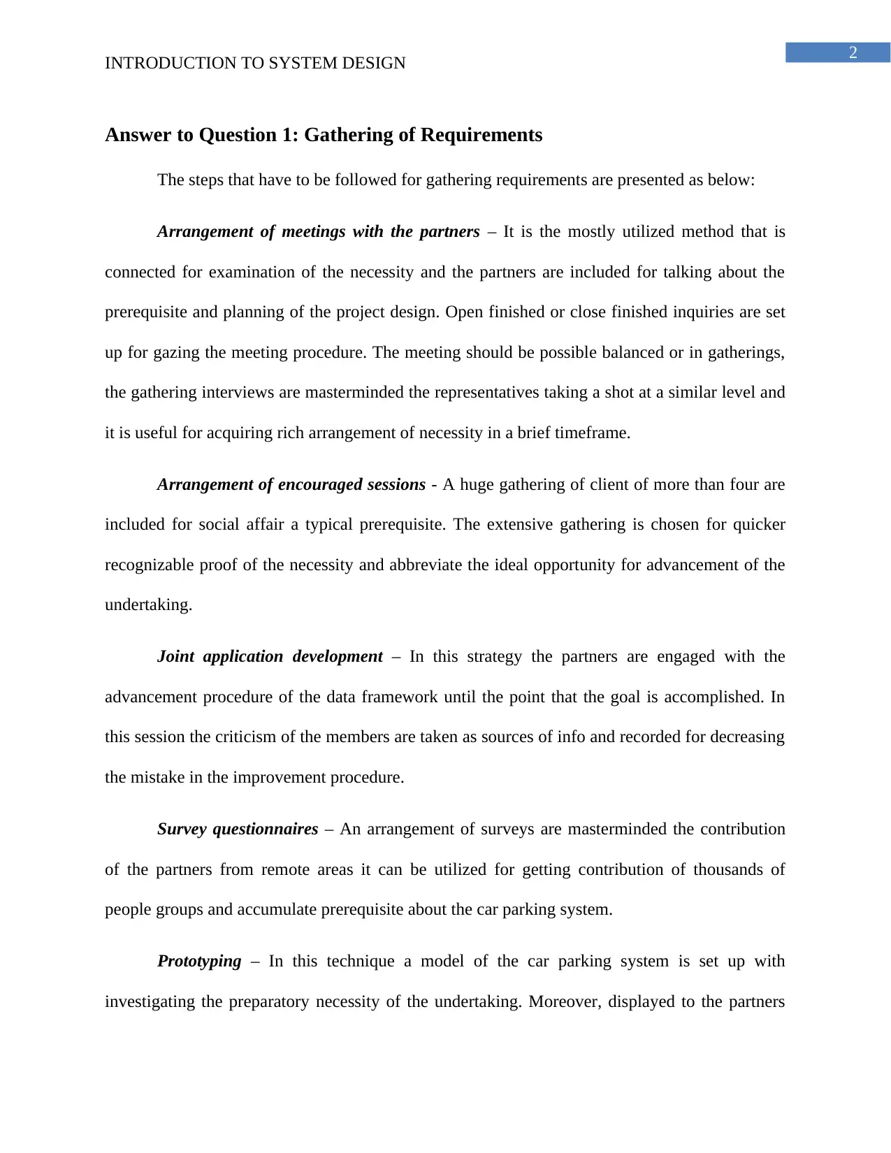
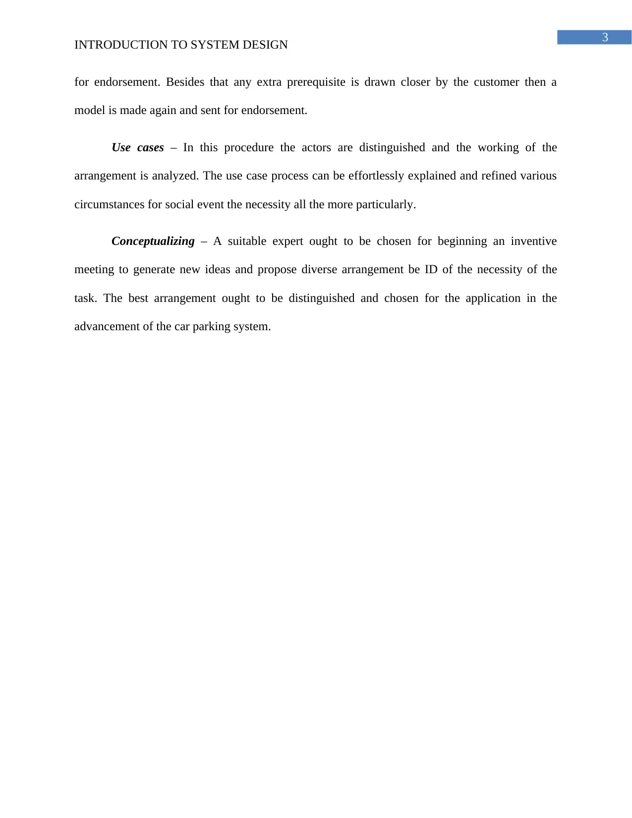
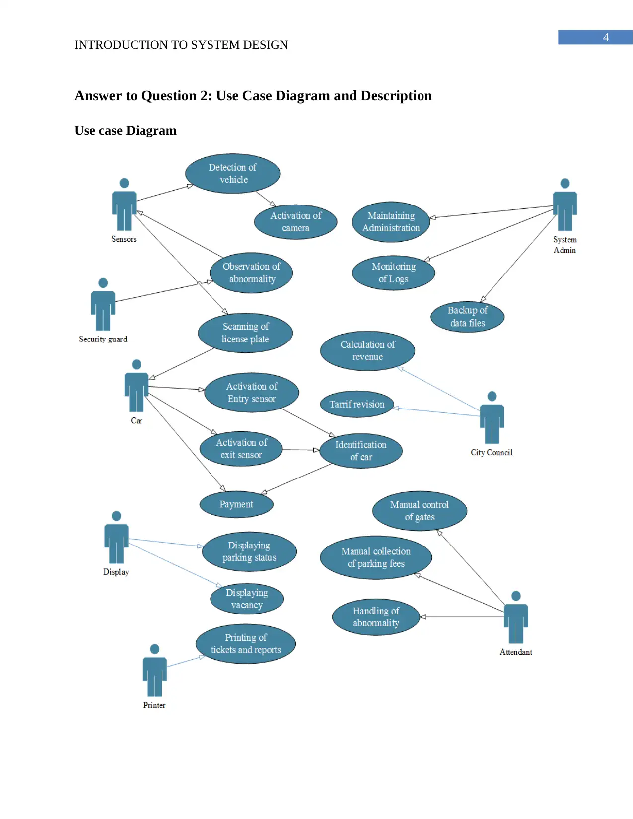
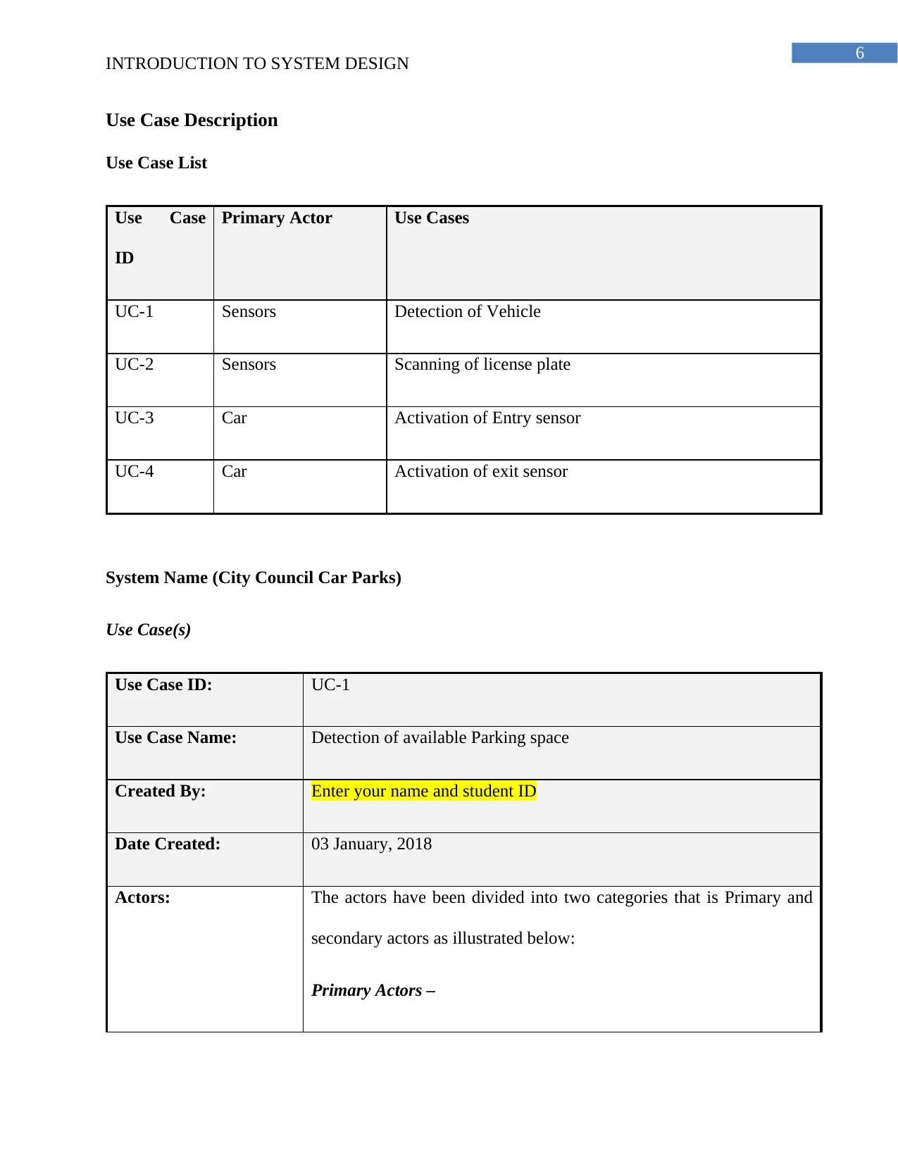
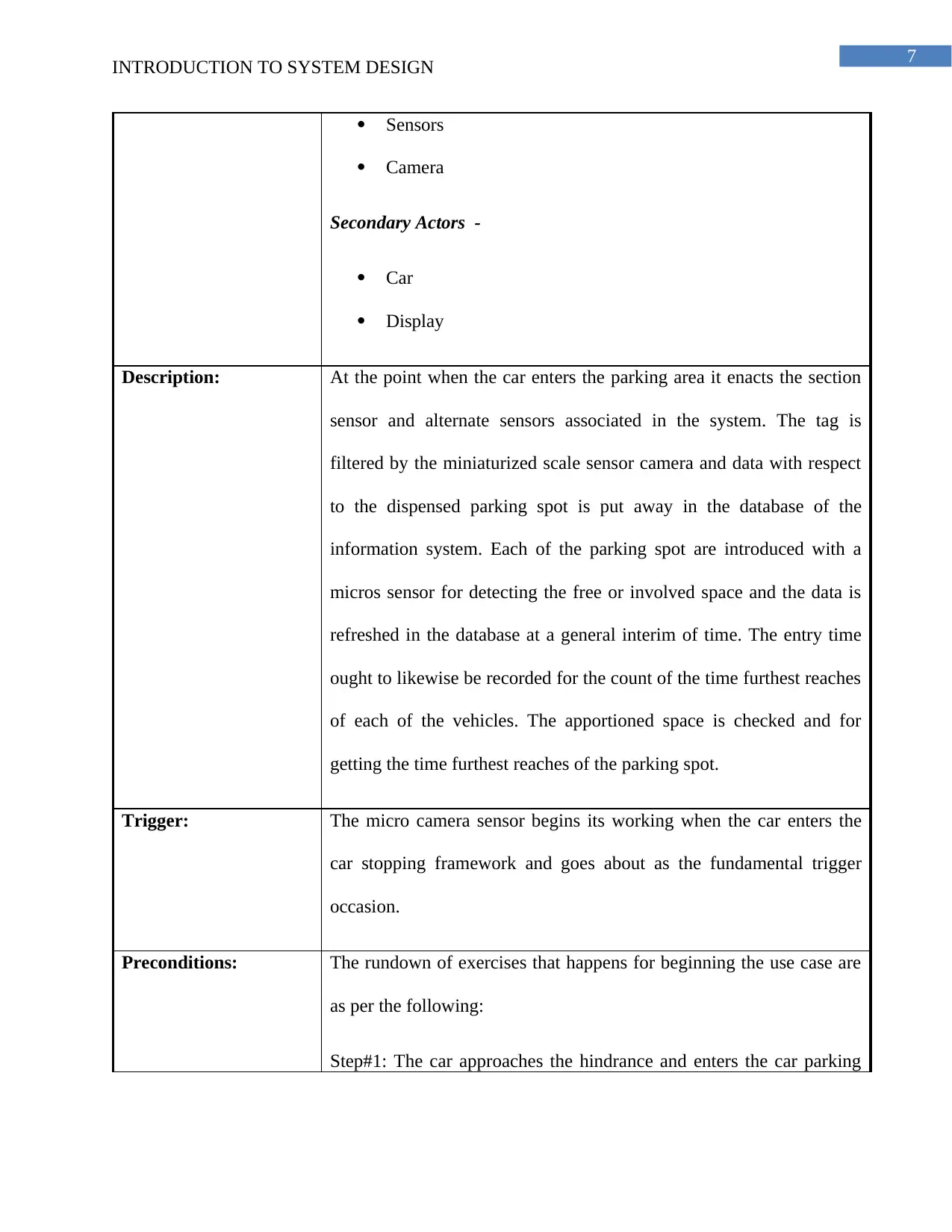
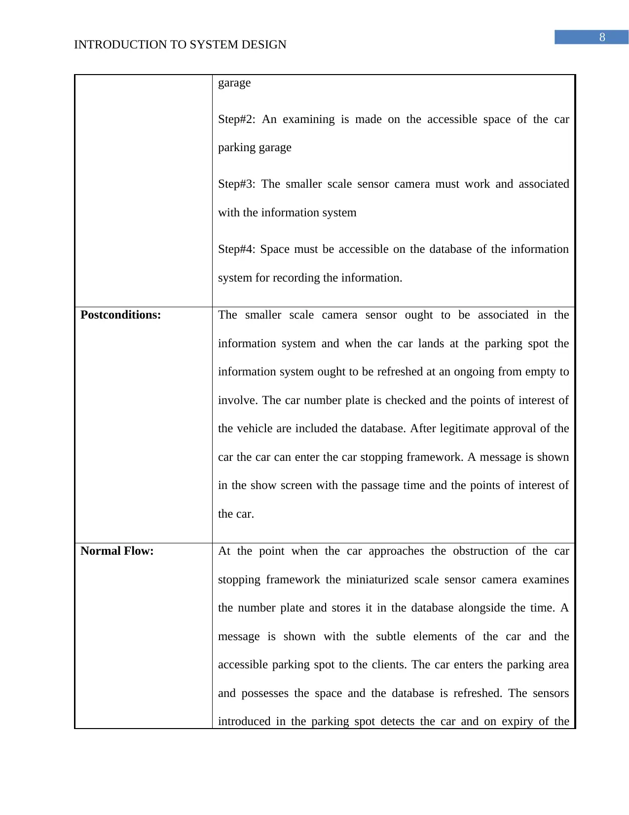
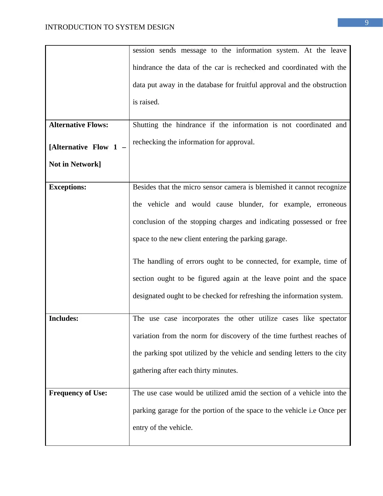
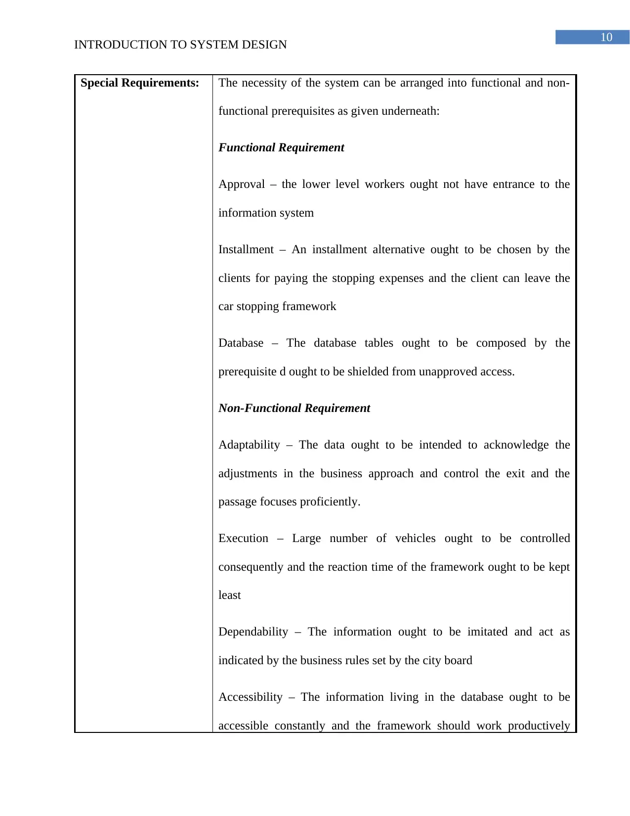
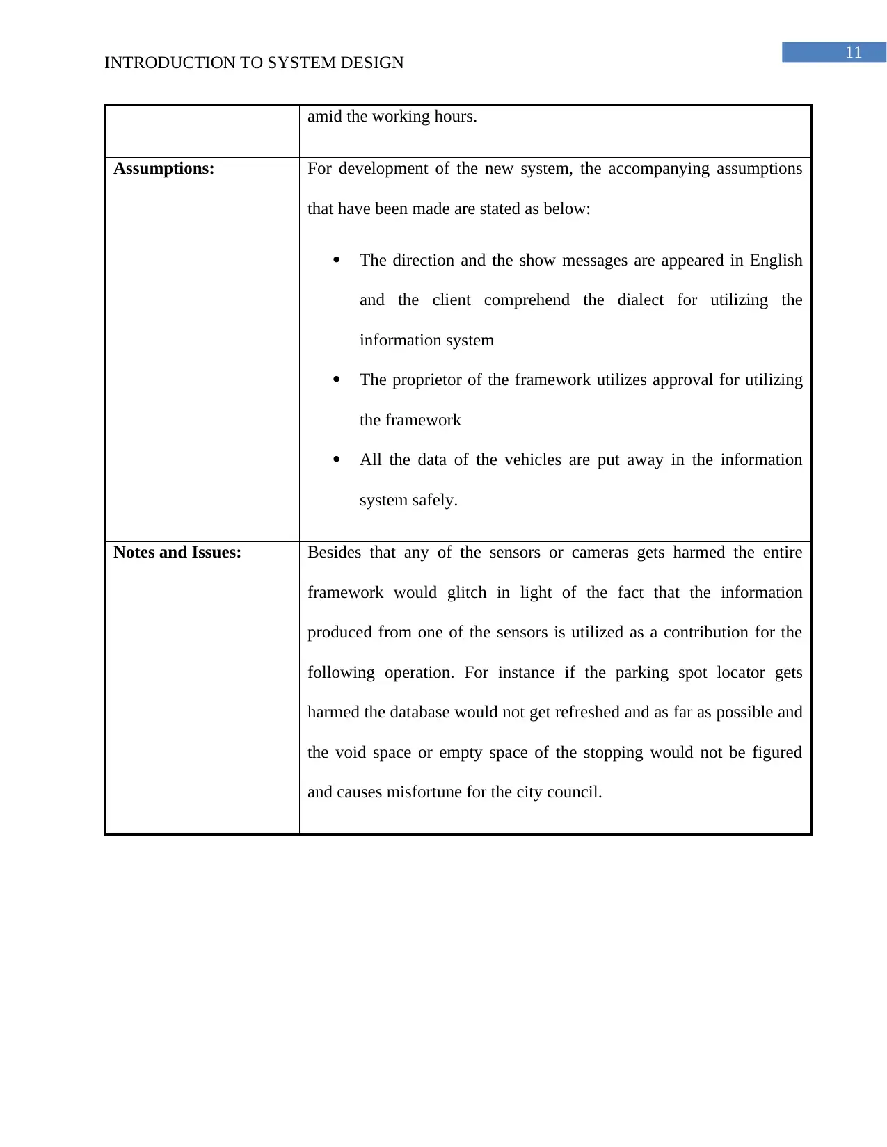
This report provides an in-depth analysis of system design principles, focusing on requirements gathering and use case diagrams for a car parking system. The report begins by outlining the steps involved in gathering requirements, including meetings with stakeholders, facilitated sessions, joint application development, review questionnaires, prototyping, use cases, and conceptualizing. It then presents a detailed use case diagram and descriptions for the car parking system, including actors, descriptions, triggers, preconditions, postconditions, normal and alternative flows, exceptions, and special requirements. The use case focuses on the detection of available parking spaces using sensors and cameras. The report also discusses functional and non-functional requirements, such as approval, payment options, database design, adaptability, performance, dependability, and accessibility. Finally, the report includes assumptions and notes on potential issues. The bibliography provides a list of relevant research papers on system design and use case modeling.
Document Page
Running head: INTRODUCTION TO SYSTEM DESIGN
Introduction to System Design
Name of the Student:
Name of the University:
tabler-icon-diamond-filled.svg

Secure Best Marks with AI Grader

Need help grading? Try our AI Grader for instant feedback on your assignments.
Document Page
1
INTRODUCTION TO SYSTEM DESIGN
Table of Contents
Answer to Question 1: Gathering of Requirements.........................................................................2
Answer to Question 2: Use Case Diagram and Description............................................................4
Use case Diagram........................................................................................................................4
Use Case Description...................................................................................................................5
Bibliography..................................................................................................................................11
Document Page
2
INTRODUCTION TO SYSTEM DESIGN
Answer to Question 1: Gathering of Requirements
The steps that have to be followed for gathering requirements are presented as below:
Arrangement of meetings with the partners – It is the mostly utilized method that is
connected for examination of the necessity and the partners are included for talking about the
prerequisite and planning of the project design. Open finished or close finished inquiries are set
up for gazing the meeting procedure. The meeting should be possible balanced or in gatherings,
the gathering interviews are masterminded the representatives taking a shot at a similar level and
it is useful for acquiring rich arrangement of necessity in a brief timeframe.
Arrangement of encouraged sessions - A huge gathering of client of more than four are
included for social affair a typical prerequisite. The extensive gathering is chosen for quicker
recognizable proof of the necessity and abbreviate the ideal opportunity for advancement of the
undertaking.
Joint application development – In this strategy the partners are engaged with the
advancement procedure of the data framework until the point that the goal is accomplished. In
this session the criticism of the members are taken as sources of info and recorded for decreasing
the mistake in the improvement procedure.
Survey questionnaires – An arrangement of surveys are masterminded the contribution
of the partners from remote areas it can be utilized for getting contribution of thousands of
people groups and accumulate prerequisite about the car parking system.
Prototyping – In this technique a model of the car parking system is set up with
investigating the preparatory necessity of the undertaking. Moreover, displayed to the partners
Document Page
3
INTRODUCTION TO SYSTEM DESIGN
for endorsement. Besides that any extra prerequisite is drawn closer by the customer then a
model is made again and sent for endorsement.
Use cases – In this procedure the actors are distinguished and the working of the
arrangement is analyzed. The use case process can be effortlessly explained and refined various
circumstances for social event the necessity all the more particularly.
Conceptualizing – A suitable expert ought to be chosen for beginning an inventive
meeting to generate new ideas and propose diverse arrangement be ID of the necessity of the
task. The best arrangement ought to be distinguished and chosen for the application in the
advancement of the car parking system.
tabler-icon-diamond-filled.svg

Secure Best Marks with AI Grader

Need help grading? Try our AI Grader for instant feedback on your assignments.
Document Page
4
INTRODUCTION TO SYSTEM DESIGN
Answer to Question 2: Use Case Diagram and Description
Use case Diagram
Document Page
5
INTRODUCTION TO SYSTEM DESIGN
Document Page
6
INTRODUCTION TO SYSTEM DESIGN
Use Case Description
Use Case List
Use Case
ID
Primary Actor Use Cases
UC-1 Sensors Detection of Vehicle
UC-2 Sensors Scanning of license plate
UC-3 Car Activation of Entry sensor
UC-4 Car Activation of exit sensor
System Name (City Council Car Parks)
Use Case(s)
Use Case ID: UC-1
Use Case Name: Detection of available Parking space
Created By: Enter your name and student ID
Date Created: 03 January, 2018
Actors: The actors have been divided into two categories that is Primary and
secondary actors as illustrated below:
Primary Actors –
tabler-icon-diamond-filled.svg

Paraphrase This Document

Need a fresh take? Get an instant paraphrase of this document with our AI Paraphraser
Document Page
7
INTRODUCTION TO SYSTEM DESIGN
Sensors
Camera
Secondary Actors -
Car
Display
Description: At the point when the car enters the parking area it enacts the section
sensor and alternate sensors associated in the system. The tag is
filtered by the miniaturized scale sensor camera and data with respect
to the dispensed parking spot is put away in the database of the
information system. Each of the parking spot are introduced with a
micros sensor for detecting the free or involved space and the data is
refreshed in the database at a general interim of time. The entry time
ought to likewise be recorded for the count of the time furthest reaches
of each of the vehicles. The apportioned space is checked and for
getting the time furthest reaches of the parking spot.
Trigger: The micro camera sensor begins its working when the car enters the
car stopping framework and goes about as the fundamental trigger
occasion.
Preconditions: The rundown of exercises that happens for beginning the use case are
as per the following:
Step#1: The car approaches the hindrance and enters the car parking
Document Page
8
INTRODUCTION TO SYSTEM DESIGN
garage
Step#2: An examining is made on the accessible space of the car
parking garage
Step#3: The smaller scale sensor camera must work and associated
with the information system
Step#4: Space must be accessible on the database of the information
system for recording the information.
Postconditions: The smaller scale camera sensor ought to be associated in the
information system and when the car lands at the parking spot the
information system ought to be refreshed at an ongoing from empty to
involve. The car number plate is checked and the points of interest of
the vehicle are included the database. After legitimate approval of the
car the car can enter the car stopping framework. A message is shown
in the show screen with the passage time and the points of interest of
the car.
Normal Flow: At the point when the car approaches the obstruction of the car
stopping framework the miniaturized scale sensor camera examines
the number plate and stores it in the database alongside the time. A
message is shown with the subtle elements of the car and the
accessible parking spot to the clients. The car enters the parking area
and possesses the space and the database is refreshed. The sensors
introduced in the parking spot detects the car and on expiry of the
Document Page
9
INTRODUCTION TO SYSTEM DESIGN
session sends message to the information system. At the leave
hindrance the data of the car is rechecked and coordinated with the
data put away in the database for fruitful approval and the obstruction
is raised.
Alternative Flows:
[Alternative Flow 1
Not in Network]
Shutting the hindrance if the information is not coordinated and
rechecking the information for approval.
Exceptions: Besides that the micro sensor camera is blemished it cannot recognize
the vehicle and would cause blunder, for example, erroneous
conclusion of the stopping charges and indicating possessed or free
space to the new client entering the parking garage.
The handling of errors ought to be connected, for example, time of
section ought to be figured again at the leave point and the space
designated ought to be checked for refreshing the information system.
Includes: The use case incorporates the other utilize cases like spectator
variation from the norm for discovery of the time furthest reaches of
the parking spot utilized by the vehicle and sending letters to the city
gathering after each thirty minutes.
Frequency of Use: The use case would be utilized amid the section of a vehicle into the
parking garage for the portion of the space to the vehicle i.e Once per
entry of the vehicle.
tabler-icon-diamond-filled.svg

Secure Best Marks with AI Grader

Need help grading? Try our AI Grader for instant feedback on your assignments.
Document Page
10
INTRODUCTION TO SYSTEM DESIGN
Special Requirements: The necessity of the system can be arranged into functional and non-
functional prerequisites as given underneath:
Functional Requirement
Approval – the lower level workers ought not have entrance to the
information system
Installment – An installment alternative ought to be chosen by the
clients for paying the stopping expenses and the client can leave the
car stopping framework
Database The database tables ought to be composed by the
prerequisite d ought to be shielded from unapproved access.
Non-Functional Requirement
Adaptability – The data ought to be intended to acknowledge the
adjustments in the business approach and control the exit and the
passage focuses proficiently.
Execution Large number of vehicles ought to be controlled
consequently and the reaction time of the framework ought to be kept
least
Dependability – The information ought to be imitated and act as
indicated by the business rules set by the city board
Accessibility – The information living in the database ought to be
accessible constantly and the framework should work productively
Document Page
11
INTRODUCTION TO SYSTEM DESIGN
amid the working hours.
Assumptions: For development of the new system, the accompanying assumptions
that have been made are stated as below:
The direction and the show messages are appeared in English
and the client comprehend the dialect for utilizing the
information system
The proprietor of the framework utilizes approval for utilizing
the framework
All the data of the vehicles are put away in the information
system safely.
Notes and Issues: Besides that any of the sensors or cameras gets harmed the entire
framework would glitch in light of the fact that the information
produced from one of the sensors is utilized as a contribution for the
following operation. For instance if the parking spot locator gets
harmed the database would not get refreshed and as far as possible and
the void space or empty space of the stopping would not be figured
and causes misfortune for the city council.
Document Page
12
INTRODUCTION TO SYSTEM DESIGN
Bibliography
Al-alshuhai, A. and Siewe, F., 2015, November. An extension of the use case diagram to model
context-aware applications. In SAI Intelligent Systems Conference (IntelliSys), 2015 (pp. 884-
888). IEEE.
Al-Fedaghi, S., 2014. Information system requirements: a flow-based diagram versus
supplementation of use case narratives with activity diagrams. International Journal of Business
Information Systems, 17(3), pp.306-322.
Gulia, S. and Choudhury, T., 2016, January. An efficient automated design to generate UML
diagram from Natural Language Specifications. In Cloud System and Big Data Engineering
(Confluence), 2016 6th International Conference(pp. 641-648). IEEE.
Hazra, R. and Dey, S., 2014. Consistency between Use Case, Sequence and Timing Diagram for
Real Time Software Systems. International Journal of Computer Applications, 85(16).
Jena, A.K., Swain, S.K. and Mohapatra, D.P., 2014, February. A novel approach for test case
generation from UML activity diagram. In Issues and Challenges in Intelligent Computing
Techniques (ICICT), 2014 International Conference on (pp. 621-629). IEEE.
Krainer, D., Ströckl, D.E. and Oberzaucher, J., 2017, June. Use Case Focused User-Interaction
Diagram: A Communication Tool within AAL Projects. In Proceedings of the 10th International
Conference on PErvasive Technologies Related to Assistive Environments (pp. 193-196). ACM.
Li, Y. and Jiang, L., 2014, August. The research on test case generation technology of UML
sequence diagram. In Computer Science & Education (ICCSE), 2014 9th International
Conference on (pp. 1067-1069). IEEE.
tabler-icon-diamond-filled.svg

Paraphrase This Document

Need a fresh take? Get an instant paraphrase of this document with our AI Paraphraser
Document Page
13
INTRODUCTION TO SYSTEM DESIGN
Misra, S.K., 2014. Test scenario generation and prioritization from UML 2. x sequence
diagram (Doctoral dissertation).
Reggio, G., Leotta, M., Ricca, F. and Clerissi, D., 2014, January. What are the used UML
diagram constructs? A document and tool analysis study covering activity and use case diagrams.
In International Conference on Model-Driven Engineering and Software Development (pp. 66-
83). Springer, Cham.
Reggio, G., Leotta, M., Ricca, F. and Clerissi, D., 2014, January. What are the used UML
diagram constructs? A document and tool analysis study covering activity and use case diagrams.
In International Conference on Model-Driven Engineering and Software Development (pp. 66-
83). Springer, Cham.
Rhmann, W., Zaidi, T. and Saxena, V., 2015. Use of Genetic Approach for Test Case
Prioritization from UML Activity Diagram. International Journal of Computer
Applications, 115(4).
Sabharwal, S., Kaur, P. and Sibal, R., 2017. Theoretical and Empirical Validation of Use Case
Diagram Complexity Metric. International Journal of Mathematical and Computational
Methods, 2.
chevron_up_icon
1 out of 14
circle_padding
hide_on_mobile
zoom_out_icon
logo.png

Your All-in-One AI-Powered Toolkit for Academic Success.

Available 24*7 on WhatsApp / Email

[object Object]