System Analysis and Design: Modeling with UML Diagrams IMAT5205
VerifiedAdded on 2023/04/20
|12
|2170
|463
Report
AI Summary
This report provides a comprehensive overview of system analysis and design, focusing on modeling techniques using UML diagrams. It includes a class diagram illustrating the system's structure, a communication diagram detailing object interactions, and a sequence diagram emphasizing the chronological exchange of information. The report also evaluates CASE tools and their role in automating the software development process, highlighting their benefits in reducing costs and improving system quality. The diagrams created in the report showcase the conceptual model proposed for a new information system, demonstrating the relationships and operations between classes such as clerical assistant, tour leader, and passenger. This document is available on Desklib, a platform offering a wide range of study resources, including past papers and solved assignments for students.
Running head: SYSTEM ANALYSIS AND DESIGN
System Analysis and Design
Name of Student-
Name of University-
Author’s Note-
System Analysis and Design
Name of Student-
Name of University-
Author’s Note-
Paraphrase This Document
Need a fresh take? Get an instant paraphrase of this document with our AI Paraphraser

1SYSTEM ANALYSIS AND DESIGN
Part 1:
Analysis Class Diagram
a) Analysis of Class Diagram: Class diagram is basically considered as a type of diagram
and is also considered as the part of the UML (Unified Modelling Language) Languages. Class
diagram defines the structure of the system and provides the user and the reader the structure of
the system that defines the classes, operations or methods that the class will perform in the
system and their related attributes (Turco, Pietro and Martignano 2018). Class diagram also
offers relationships between various classes. The class diagram also illustrates functional
diagram of the system that is being designed and serve the developer as development resource in
the software development life cycle. Class diagram provides conceptual diagram to the
developers.
2SYSTEM ANALYSIS AND DESIGN
b) Class Diagram
Figure 1: Class Diagram
(Source: Created by author on Enterprise Architect)
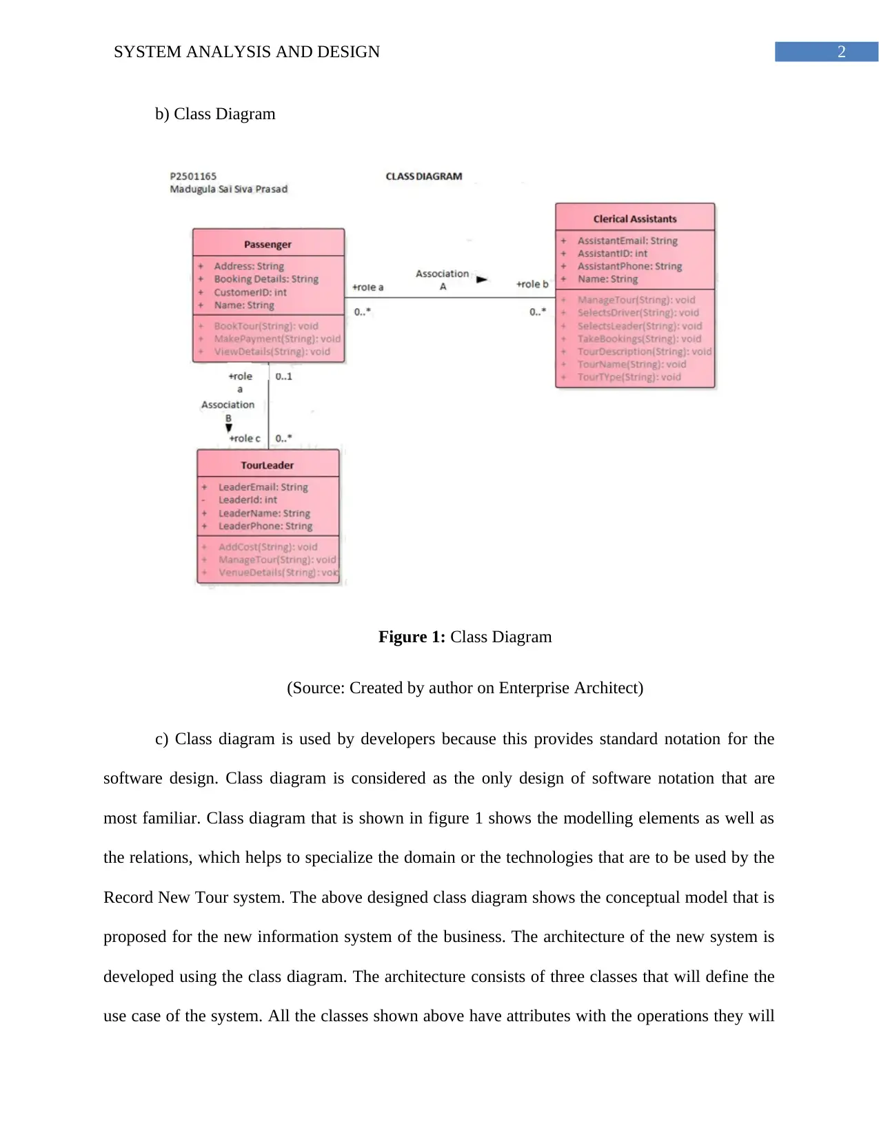
c) Class diagram is used by developers because this provides standard notation for the
software design. Class diagram is considered as the only design of software notation that are
most familiar. Class diagram that is shown in figure 1 shows the modelling elements as well as
the relations, which helps to specialize the domain or the technologies that are to be used by the
Record New Tour system. The above designed class diagram shows the conceptual model that is
proposed for the new information system of the business. The architecture of the new system is
developed using the class diagram. The architecture consists of three classes that will define the
use case of the system. All the classes shown above have attributes with the operations they will
b) Class Diagram
Figure 1: Class Diagram
(Source: Created by author on Enterprise Architect)
c) Class diagram is used by developers because this provides standard notation for the
software design. Class diagram is considered as the only design of software notation that are
most familiar. Class diagram that is shown in figure 1 shows the modelling elements as well as
the relations, which helps to specialize the domain or the technologies that are to be used by the
Record New Tour system. The above designed class diagram shows the conceptual model that is
proposed for the new information system of the business. The architecture of the new system is
developed using the class diagram. The architecture consists of three classes that will define the
use case of the system. All the classes shown above have attributes with the operations they will
⊘ This is a preview!⊘
Do you want full access?
Subscribe today to unlock all pages.
Trusted by 1+ million students worldwide
3SYSTEM ANALYSIS AND DESIGN
perform in the new information system. The classes defined above are clerical assistant class,
tour leader class and the passenger class that have different operations in the new system. All the
classes are associated with each other.
Communication Diagram
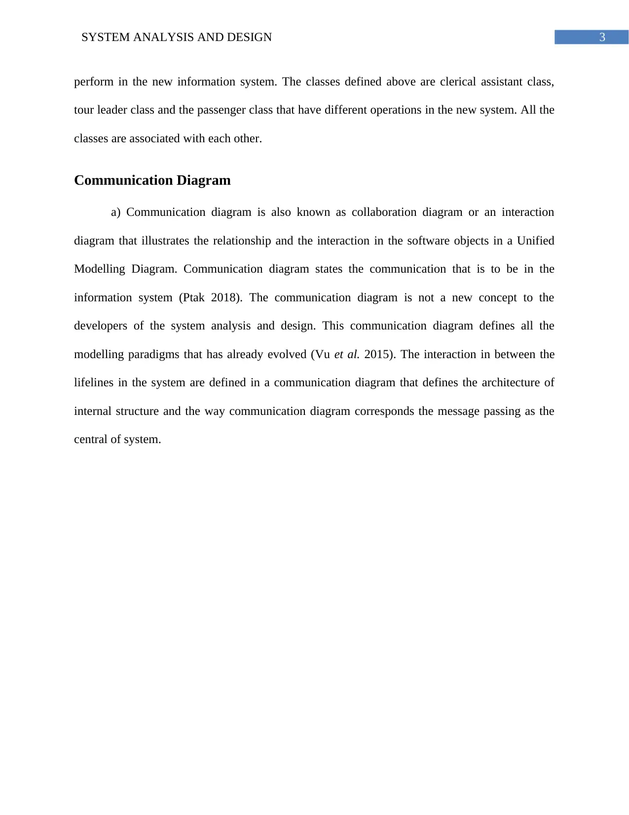
a) Communication diagram is also known as collaboration diagram or an interaction
diagram that illustrates the relationship and the interaction in the software objects in a Unified
Modelling Diagram. Communication diagram states the communication that is to be in the
information system (Ptak 2018). The communication diagram is not a new concept to the
developers of the system analysis and design. This communication diagram defines all the
modelling paradigms that has already evolved (Vu et al. 2015). The interaction in between the
lifelines in the system are defined in a communication diagram that defines the architecture of
internal structure and the way communication diagram corresponds the message passing as the
central of system.
perform in the new information system. The classes defined above are clerical assistant class,
tour leader class and the passenger class that have different operations in the new system. All the
classes are associated with each other.
Communication Diagram
a) Communication diagram is also known as collaboration diagram or an interaction
diagram that illustrates the relationship and the interaction in the software objects in a Unified
Modelling Diagram. Communication diagram states the communication that is to be in the
information system (Ptak 2018). The communication diagram is not a new concept to the
developers of the system analysis and design. This communication diagram defines all the
modelling paradigms that has already evolved (Vu et al. 2015). The interaction in between the
lifelines in the system are defined in a communication diagram that defines the architecture of
internal structure and the way communication diagram corresponds the message passing as the
central of system.
Paraphrase This Document
Need a fresh take? Get an instant paraphrase of this document with our AI Paraphraser
4SYSTEM ANALYSIS AND DESIGN
b) Communication diagram
Figure 2: Communication Diagram
(Source: Created by author on Enterprise Architect)
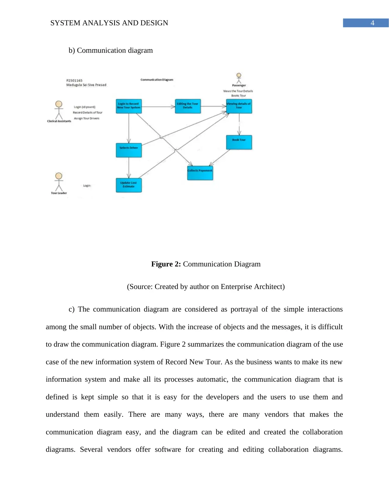
c) The communication diagram are considered as portrayal of the simple interactions
among the small number of objects. With the increase of objects and the messages, it is difficult
to draw the communication diagram. Figure 2 summarizes the communication diagram of the use
case of the new information system of Record New Tour. As the business wants to make its new
information system and make all its processes automatic, the communication diagram that is
defined is kept simple so that it is easy for the developers and the users to use them and
understand them easily. There are many ways, there are many vendors that makes the
communication diagram easy, and the diagram can be edited and created the collaboration
diagrams. Several vendors offer software for creating and editing collaboration diagrams.
b) Communication diagram
Figure 2: Communication Diagram
(Source: Created by author on Enterprise Architect)
c) The communication diagram are considered as portrayal of the simple interactions
among the small number of objects. With the increase of objects and the messages, it is difficult
to draw the communication diagram. Figure 2 summarizes the communication diagram of the use
case of the new information system of Record New Tour. As the business wants to make its new
information system and make all its processes automatic, the communication diagram that is
defined is kept simple so that it is easy for the developers and the users to use them and
understand them easily. There are many ways, there are many vendors that makes the
communication diagram easy, and the diagram can be edited and created the collaboration
diagrams. Several vendors offer software for creating and editing collaboration diagrams.
5SYSTEM ANALYSIS AND DESIGN
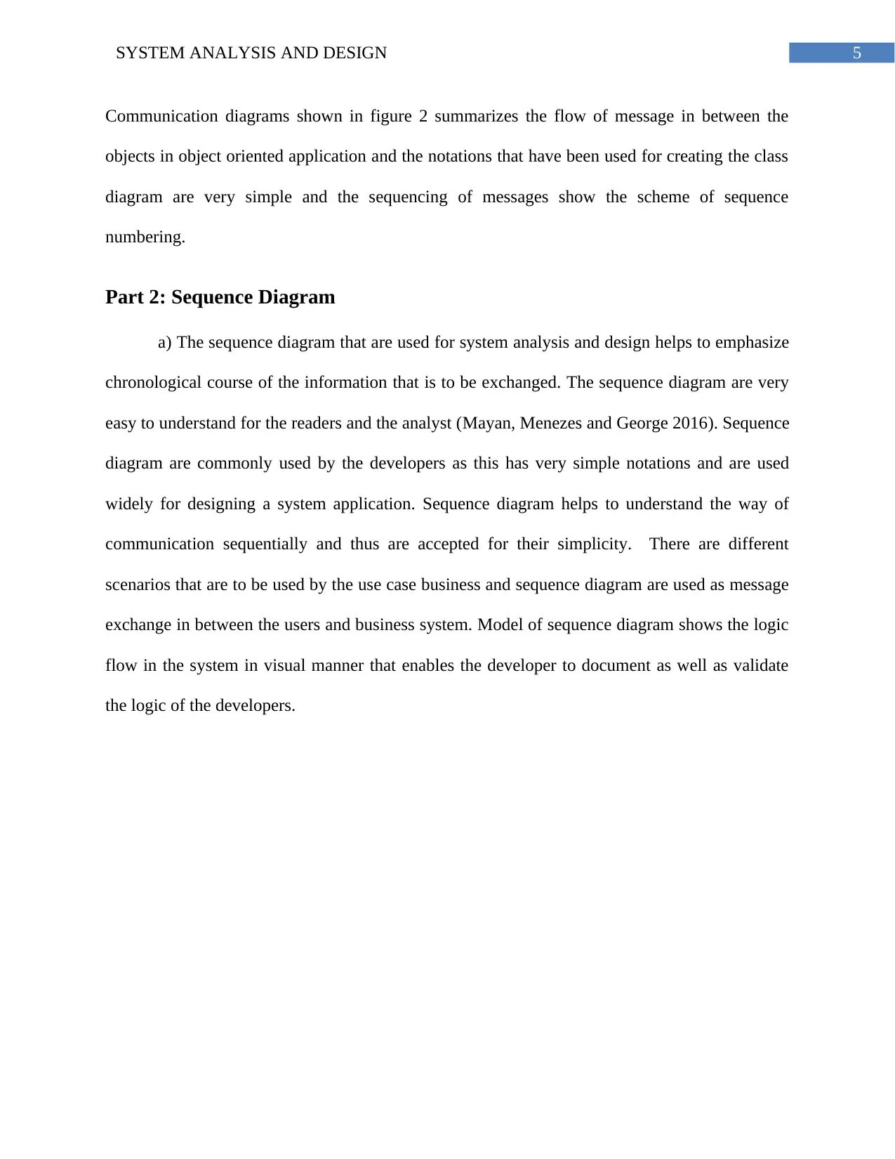
Communication diagrams shown in figure 2 summarizes the flow of message in between the
objects in object oriented application and the notations that have been used for creating the class
diagram are very simple and the sequencing of messages show the scheme of sequence
numbering.
Part 2: Sequence Diagram
a) The sequence diagram that are used for system analysis and design helps to emphasize
chronological course of the information that is to be exchanged. The sequence diagram are very
easy to understand for the readers and the analyst (Mayan, Menezes and George 2016). Sequence
diagram are commonly used by the developers as this has very simple notations and are used
widely for designing a system application. Sequence diagram helps to understand the way of
communication sequentially and thus are accepted for their simplicity. There are different
scenarios that are to be used by the use case business and sequence diagram are used as message
exchange in between the users and business system. Model of sequence diagram shows the logic
flow in the system in visual manner that enables the developer to document as well as validate
the logic of the developers.
⊘ This is a preview!⊘
Do you want full access?
Subscribe today to unlock all pages.
Trusted by 1+ million students worldwide
6SYSTEM ANALYSIS AND DESIGN
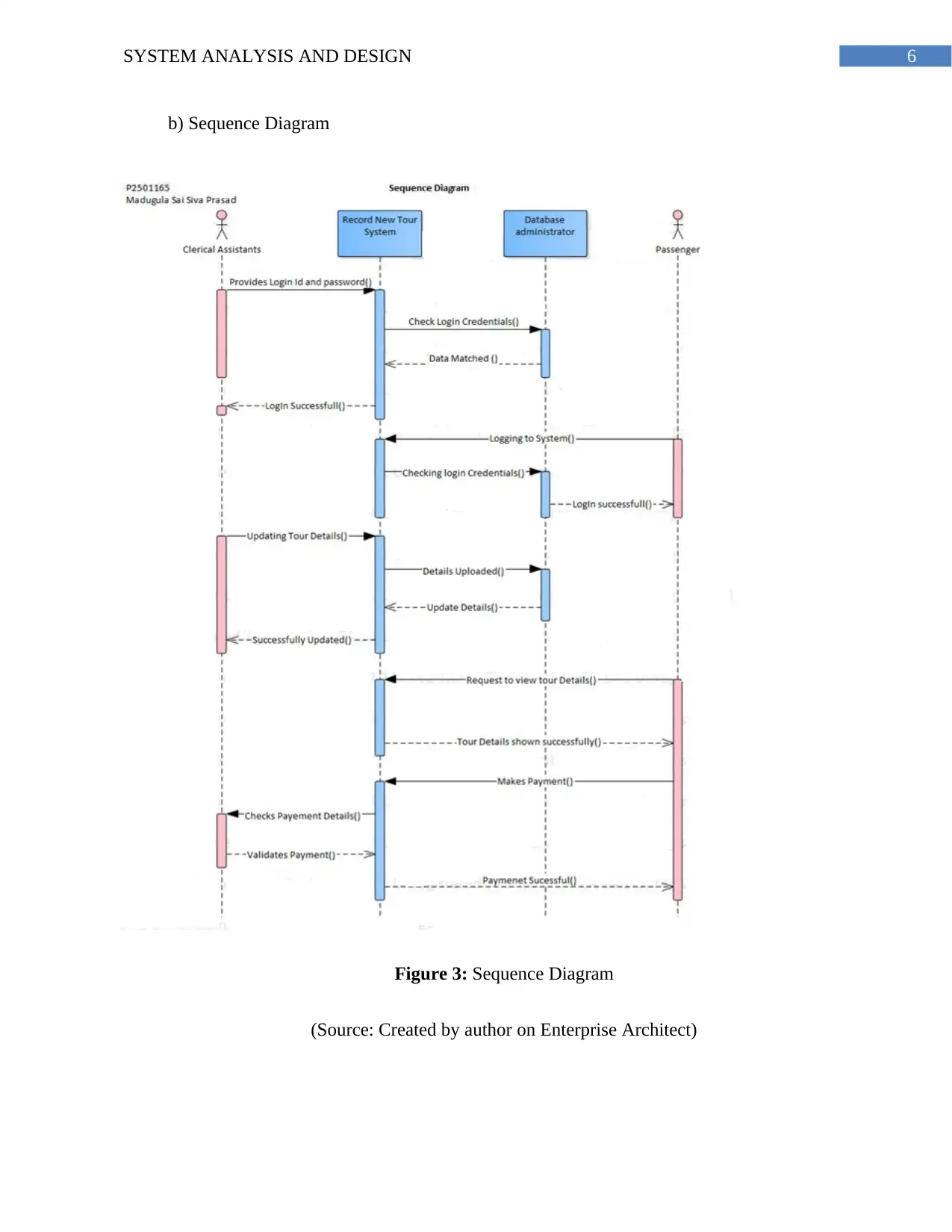
b) Sequence Diagram
Figure 3: Sequence Diagram
(Source: Created by author on Enterprise Architect)
b) Sequence Diagram
Figure 3: Sequence Diagram
(Source: Created by author on Enterprise Architect)
Paraphrase This Document
Need a fresh take? Get an instant paraphrase of this document with our AI Paraphraser
7SYSTEM ANALYSIS AND DESIGN
c) The messages that are shown in the above sequence diagram of the new information
system of the business tour company. The messages shown in the diagram shows the source and
the target of the messages that are to be exchanged in the system. The sequence diagram shown
in figure 3 shows the actors who have to interact within the system of Record New Tour. There
are objects that are involved in the sequence diagram that shows are included in the
communication in the sequence diagram. The diagram shown above shows the messages that
passes from one object to another by and the flow of messages are shown by arrow and are
labelled accordingly. The target of the message are objects that are shown in the sequence
diagram, which indicates the method that is to be invoked as a response in the system. The above
show sequence diagram shows the responsibilities for the classes and the objects and the new
classes that are used for the system analysis and design. Sequence diagram shows dynamic
modelling that id used for identifying behaviour of the system.
Part 3: Evaluation
CASE is defined as automation on entire development process or on part of the
development process. CASE tools includes products that are computer based which supports
more than one phases in the System Development Life Cycle. The CASE tools helps in reducing
or in eliminating many design as well as development problems that inherits in the projects.
There are main two reasons used for utilizing the CASE tool. The reasons are reducing the
amount of the money and time on the projects and improving quality of the system that is
developed.
An environment of CASE is mainly defined as the collection of all tools that are used for
designing the system and includes all the components with integrated approach for supporting
the interaction that is to be accrued out in the system (Kaur and Sehra 2015). The interaction is
8SYSTEM ANALYSIS AND DESIGN
between the environment and the components. The CASE environment also includes various
CASE tools, which helps to operate on a platform that has a common hardware and software
system. The CASE tool has one of the disadvantage that includes lack of interoperability that are
assembled in the CASE tool.
CASE (Computer Aided Software Engineering) is a domain that includes software tools
that are used to design and then implements the applications. The CASE tools are very easy and
are inspired by the CAD (Computer Aided Tools) that are used for designing the products for
designing the hardware. Very high of software, with all maintenance quality and detect free that
are used in the CASE tools software (Rumpe 2016). The software that are used in CASE tools
are associated with the methods that are used for developing the information system along with
the automated tools that are to be used by the process of developing a software.
The CASE tools that supports some particular tasks includes software life cycle that
includes workbenches. The workbenches has more than one or more tools that are focused on
some of the particular part that are included in the life cycle of the software. The tools also
supports environment that includes more than one tools or some workbenches and supports
complete life cycle of the software.
The tool that are included in CASE supports some particular tasks for developing the
software life cycle. The tasks are divided in some categories. One category includes modelling
analysis and business that includes tools of graphical modelling entity relationship modelling and
object modelling (Frank et al. 2016). There are development design and the construction phase in
the life cycle that involves debugging environments. CASE tool also includes verification as well
as validation that helps to analyse the code and specifications for performance, and the
correctness. There is configuration management that control check in as well as check out of the
⊘ This is a preview!⊘
Do you want full access?
Subscribe today to unlock all pages.
Trusted by 1+ million students worldwide
9SYSTEM ANALYSIS AND DESIGN
repository objects and the files that are included. There are metrics and the measurements that
helps to analyse the complexity of the code and the modularity performance and helps to make
the project plan and schedule the tasks accordingly.
The CASE tools are considered as cluster of software that helps in automating the
activities included in different phases of life cycle (Sahaf et al. 2014). As for example, the
functional requirements that are needed for an application and the prototyping tools are to be
used for developing the graphic models of the applications and helps to visualize the look of the
application after the development process will be finished. The designers of the system can also
use the tools of automated design that are used to transform all the functional requirement of
prototype that are basically used for detailed document design. The analysts use the CASE tool
for the generators of the automated codes that helps to convert the design of the documents in
some code. The automated tools included in CASE tools are used collectively or can even be
used individually by the analysts.
Paraphrase This Document
Need a fresh take? Get an instant paraphrase of this document with our AI Paraphraser
10SYSTEM ANALYSIS AND DESIGN
Bibliography
Del Turco, R.R., Di Pietro, C. and Martignano, C., 2018. Designing a multi-layered User
Interface for EVT 2: a development report. AIUCD 2018, p.105.
Frank, U., Atkinson, C., Grossmann, G. and Clark, T., 2016. Designing Models and Systems to
Support IT Management: A Case for Multilevel Modeling. In MULTI@ MoDELS (pp. 3-24).
Hare, E. and Kaplan, A., 2017. Designing Modular Software: A Case Study in Introductory
Statistics. Journal of Computational and Graphical Statistics, 26(3), pp.493-500.
Kaur, T. and Sehra, S.K., 2015. Designing and development of database testing
tool. International Journal of Computer Applications, 120(19).
Kounev, S., Huber, N., Brosig, F. and Zhu, X., 2016. A model-based approach to designing self-
aware IT systems and infrastructures. Computer, 49(7), pp.53-61.
Mayan, J.A., Menezes, R.J. and George, M.B., 2016. Designing a Customized Testing Tool for
Windows Phones Utilizing Background Agents. In Proceedings of the International Conference
on Soft Computing Systems (pp. 33-46). Springer, New Delhi.
Pedreira, O., García, F., Brisaboa, N. and Piattini, M., 2015. Gamification in software
engineering–A systematic mapping. Information and software technology, 57, pp.157-168.
Ptak, P., 2018, May. APPLICATION OF THE SOFTWARE PACKAGE LTSPICE FOR
DESIGNING AND ANALYSING THE OPERATION OF ELECTRONIC SYSTEMS.
In Proceedings of the International Scientific Conference. Volume V (Vol. 402, p. 408).
Sahaf, Z., Garousi, V., Pfahl, D., Irving, R. and Amannejad, Y., 2014, May. When to automate
software testing? decision support based on system dynamics: an industrial case study.

11SYSTEM ANALYSIS AND DESIGN
In Proceedings of the 2014 International Conference on Software and System Process (pp. 149-
158). ACM.
In Proceedings of the 2014 International Conference on Software and System Process (pp. 149-
158). ACM.
⊘ This is a preview!⊘
Do you want full access?
Subscribe today to unlock all pages.
Trusted by 1+ million students worldwide
1 out of 12
Related Documents


Your All-in-One AI-Powered Toolkit for Academic Success.
+13062052269
info@desklib.com
Available 24*7 on WhatsApp / Email
![[object Object]](/_next/static/media/star-bottom.7253800d.svg)
Unlock your academic potential
Copyright © 2020–2026 A2Z Services. All Rights Reserved. Developed and managed by ZUCOL.