Case Study Analysis: System Theory, Data Modeling, MIS Concepts
VerifiedAdded on 2019/12/04
|18
|2763
|268
Case Study
AI Summary
This case study delves into the core concepts of system theory, data modeling, and Management Information Systems (MIS). It begins by defining system theory, detailing the components of a system, and illustrating the importance of data processing. The study then explores the relationship between Transaction Processing Systems (TPS) and MIS, highlighting their roles in capturing, processing, and reporting business transactions. Data modeling is discussed, covering schematic models, Entity Relationship Diagrams (ERDs), and key notations. The case study also defines primary, foreign, and composite keys. Furthermore, the study provides a comprehensive overview of MIS, including different types of reports and their applications. Finally, it addresses the issue of unauthorized access (hacking), explaining how it is carried out, the damage it causes, and the relevant legal framework, such as the Computer Misuse Act of 1990. The study offers a detailed analysis of these crucial business and technology concepts.

CASE STUDY
1 | P a g e
1 | P a g e
Paraphrase This Document
Need a fresh take? Get an instant paraphrase of this document with our AI Paraphraser
TABLE OF CONTENTS
TASK 1......................................................................................................................................1
System theory.........................................................................................................................1
Relationship between a TPS and a MIS.................................................................................2
TASK 2......................................................................................................................................4
Data Modelling.......................................................................................................................4
Schematic models...................................................................................................................5
What notation represents........................................................................................................8
Versions of ERD.....................................................................................................................8
Define primary, foreign and composite keys.........................................................................8
TASK 3....................................................................................................................................10
What is MIS..........................................................................................................................10
TASK 4....................................................................................................................................11
Unauthorised access (hacking).............................................................................................11
How it is carried out.............................................................................................................11
REFERENCES.........................................................................................................................14
2 | P a g e

LIST OF FIGURES
Figure 1Conceptual Model....................................................................................................................1
Figure 2 Relationship between MIS and TPS........................................................................................3
3 | P a g e
Figure 1Conceptual Model....................................................................................................................1
Figure 2 Relationship between MIS and TPS........................................................................................3
3 | P a g e
⊘ This is a preview!⊘
Do you want full access?
Subscribe today to unlock all pages.

Trusted by 1+ million students worldwide
TASK 1
System theory
It can be define as phenomena which investigate both the principles common to all
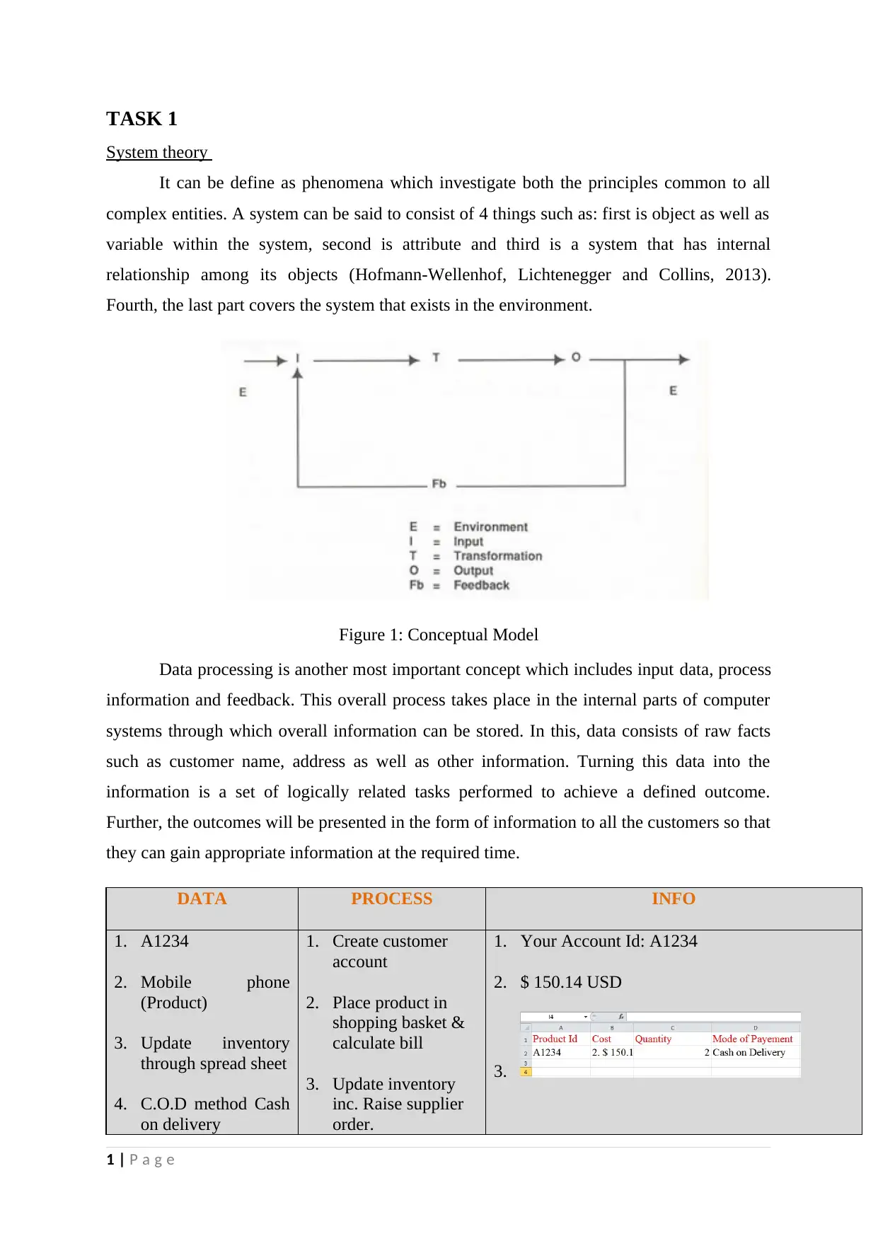
complex entities. A system can be said to consist of 4 things such as: first is object as well as
variable within the system, second is attribute and third is a system that has internal
relationship among its objects (Hofmann-Wellenhof, Lichtenegger and Collins, 2013).
Fourth, the last part covers the system that exists in the environment.
Figure 1: Conceptual Model
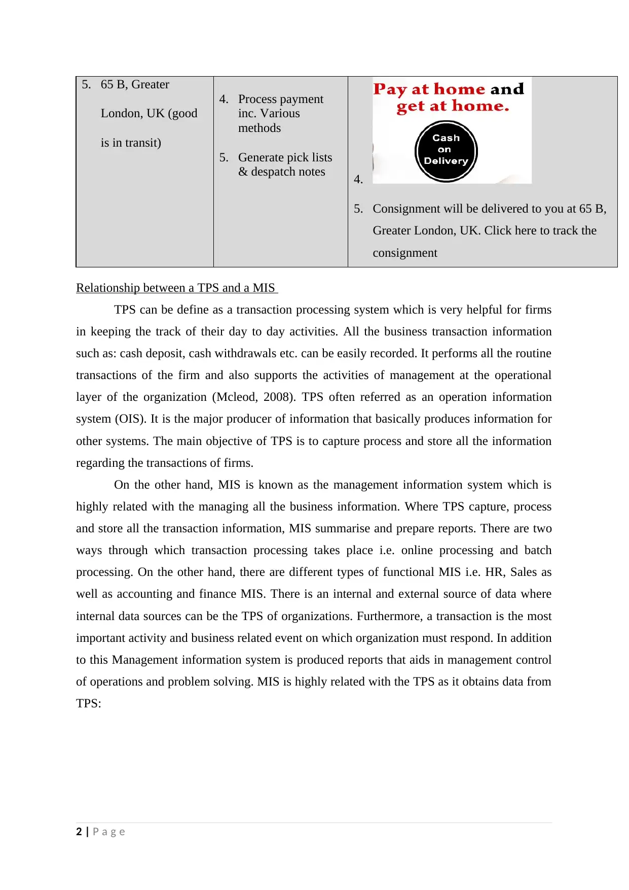
Data processing is another most important concept which includes input data, process
information and feedback. This overall process takes place in the internal parts of computer
systems through which overall information can be stored. In this, data consists of raw facts
such as customer name, address as well as other information. Turning this data into the
information is a set of logically related tasks performed to achieve a defined outcome.
Further, the outcomes will be presented in the form of information to all the customers so that
they can gain appropriate information at the required time.
DATA PROCESS INFO
1. A1234
2. Mobile phone
(Product)
3. Update inventory
through spread sheet
4. C.O.D method Cash
on delivery
1. Create customer
account
2. Place product in
shopping basket &
calculate bill
3. Update inventory
inc. Raise supplier
order.
1. Your Account Id: A1234
2. $ 150.14 USD
3.
1 | P a g e
Paraphrase This Document
Need a fresh take? Get an instant paraphrase of this document with our AI Paraphraser
5. 65 B, Greater
London, UK (good
is in transit)
4. Process payment
inc. Various
methods
5. Generate pick lists
& despatch notes 4.
5. Consignment will be delivered to you at 65 B,
Greater London, UK. Click here to track the
consignment
Relationship between a TPS and a MIS
TPS can be define as a transaction processing system which is very helpful for firms
in keeping the track of their day to day activities. All the business transaction information
such as: cash deposit, cash withdrawals etc. can be easily recorded. It performs all the routine
transactions of the firm and also supports the activities of management at the operational
layer of the organization (Mcleod, 2008). TPS often referred as an operation information
system (OIS). It is the major producer of information that basically produces information for
other systems. The main objective of TPS is to capture process and store all the information
regarding the transactions of firms.
On the other hand, MIS is known as the management information system which is
highly related with the managing all the business information. Where TPS capture, process
and store all the transaction information, MIS summarise and prepare reports. There are two
ways through which transaction processing takes place i.e. online processing and batch
processing. On the other hand, there are different types of functional MIS i.e. HR, Sales as
well as accounting and finance MIS. There is an internal and external source of data where
internal data sources can be the TPS of organizations. Furthermore, a transaction is the most
important activity and business related event on which organization must respond. In addition
to this Management information system is produced reports that aids in management control
of operations and problem solving. MIS is highly related with the TPS as it obtains data from
TPS:
2 | P a g e
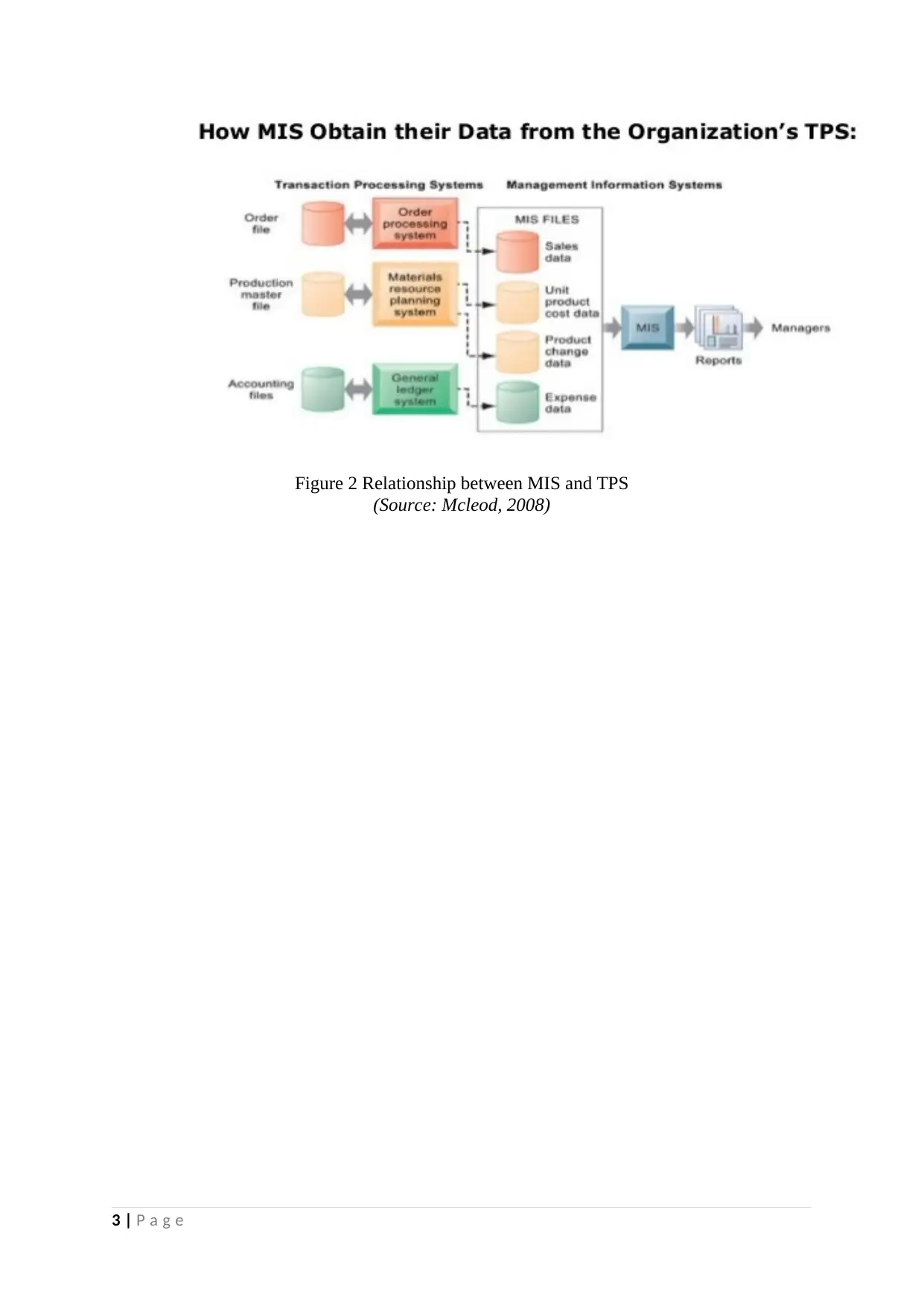
Figure 2 Relationship between MIS and TPS
(Source: Mcleod, 2008)
3 | P a g e
(Source: Mcleod, 2008)
3 | P a g e
⊘ This is a preview!⊘
Do you want full access?
Subscribe today to unlock all pages.

Trusted by 1+ million students worldwide
TASK 2
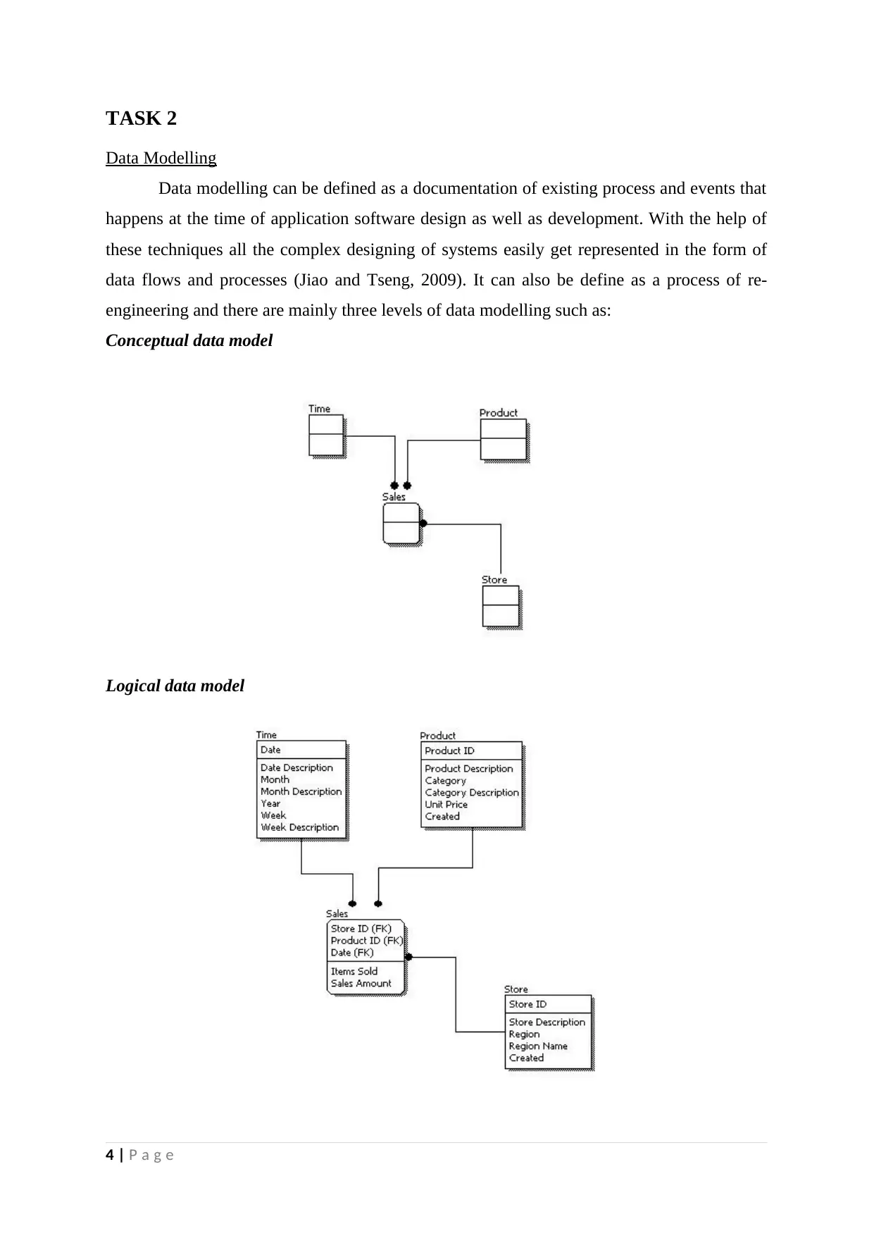
Data Modelling
Data modelling can be defined as a documentation of existing process and events that
happens at the time of application software design as well as development. With the help of
these techniques all the complex designing of systems easily get represented in the form of
data flows and processes (Jiao and Tseng, 2009). It can also be define as a process of re-
engineering and there are mainly three levels of data modelling such as:
Conceptual data model
Logical data model
4 | P a g e
Paraphrase This Document
Need a fresh take? Get an instant paraphrase of this document with our AI Paraphraser
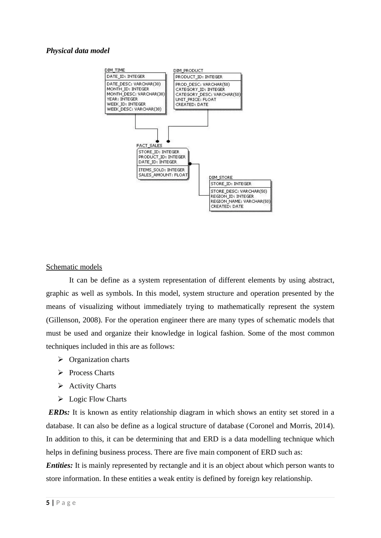
Physical data model
Schematic models
It can be define as a system representation of different elements by using abstract,
graphic as well as symbols. In this model, system structure and operation presented by the
means of visualizing without immediately trying to mathematically represent the system
(Gillenson, 2008). For the operation engineer there are many types of schematic models that
must be used and organize their knowledge in logical fashion. Some of the most common
techniques included in this are as follows:
Organization charts
Process Charts
Activity Charts
Logic Flow Charts
ERDs: It is known as entity relationship diagram in which shows an entity set stored in a
database. It can also be define as a logical structure of database (Coronel and Morris, 2014).
In addition to this, it can be determining that and ERD is a data modelling technique which
helps in defining business process. There are five main component of ERD such as:
Entities: It is mainly represented by rectangle and it is an object about which person wants to
store information. In these entities a weak entity is defined by foreign key relationship.
5 | P a g e
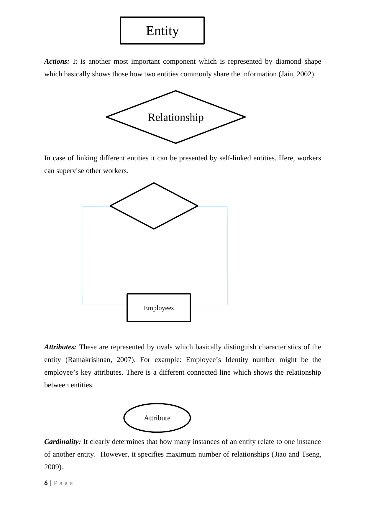
Actions: It is another most important component which is represented by diamond shape
which basically shows those how two entities commonly share the information (Jain, 2002).
In case of linking different entities it can be presented by self-linked entities. Here, workers
can supervise other workers.
Attributes: These are represented by ovals which basically distinguish characteristics of the
entity (Ramakrishnan, 2007). For example: Employee’s Identity number might be the
employee’s key attributes. There is a different connected line which shows the relationship
between entities.
Cardinality: It clearly determines that how many instances of an entity relate to one instance
of another entity. However, it specifies maximum number of relationships (Jiao and Tseng,
2009).
6 | P a g e
Entity
Relationship
Employees
Attribute
⊘ This is a preview!⊘
Do you want full access?
Subscribe today to unlock all pages.

Trusted by 1+ million students worldwide
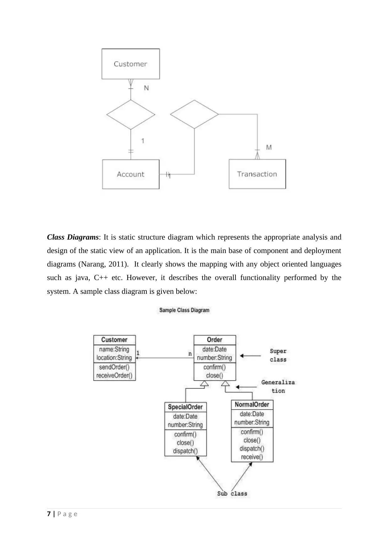
Class Diagrams: It is static structure diagram which represents the appropriate analysis and
design of the static view of an application. It is the main base of component and deployment
diagrams (Narang, 2011). It clearly shows the mapping with any object oriented languages
such as java, C++ etc. However, it describes the overall functionality performed by the
system. A sample class diagram is given below:
7 | P a g e
Paraphrase This Document
Need a fresh take? Get an instant paraphrase of this document with our AI Paraphraser
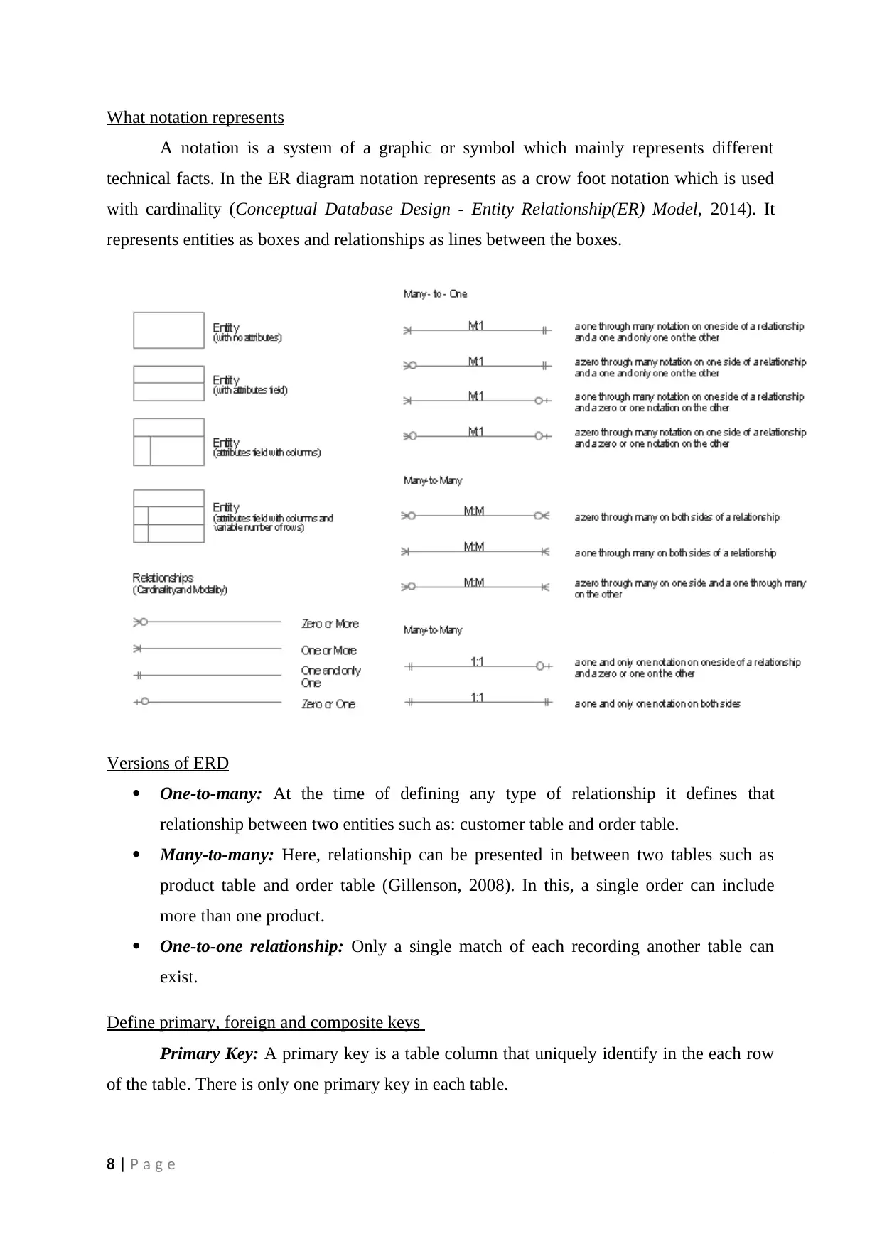
What notation represents
A notation is a system of a graphic or symbol which mainly represents different
technical facts. In the ER diagram notation represents as a crow foot notation which is used
with cardinality (Conceptual Database Design - Entity Relationship(ER) Model, 2014). It
represents entities as boxes and relationships as lines between the boxes.
Versions of ERD
One-to-many: At the time of defining any type of relationship it defines that
relationship between two entities such as: customer table and order table.
Many-to-many: Here, relationship can be presented in between two tables such as
product table and order table (Gillenson, 2008). In this, a single order can include
more than one product.
One-to-one relationship: Only a single match of each recording another table can
exist.
Define primary, foreign and composite keys
Primary Key: A primary key is a table column that uniquely identify in the each row
of the table. There is only one primary key in each table.
8 | P a g e

Foreign Key: This key is actually used to define the relationship between two tables.
User can create more than one foreign key in each table (Coronel and Morris, 2014).
Composite Key: At the time of creating keys on more than one column then that key
is known as composite key.
9 | P a g e
User can create more than one foreign key in each table (Coronel and Morris, 2014).
Composite Key: At the time of creating keys on more than one column then that key
is known as composite key.
9 | P a g e
⊘ This is a preview!⊘
Do you want full access?
Subscribe today to unlock all pages.

Trusted by 1+ million students worldwide
1 out of 18
Related Documents
Your All-in-One AI-Powered Toolkit for Academic Success.
+13062052269
info@desklib.com
Available 24*7 on WhatsApp / Email
![[object Object]](/_next/static/media/star-bottom.7253800d.svg)
Unlock your academic potential
Copyright © 2020–2026 A2Z Services. All Rights Reserved. Developed and managed by ZUCOL.


