University Systems Analysis and Design: Assignment Report
VerifiedAdded on 2022/09/12
|10
|1916
|19
Report
AI Summary
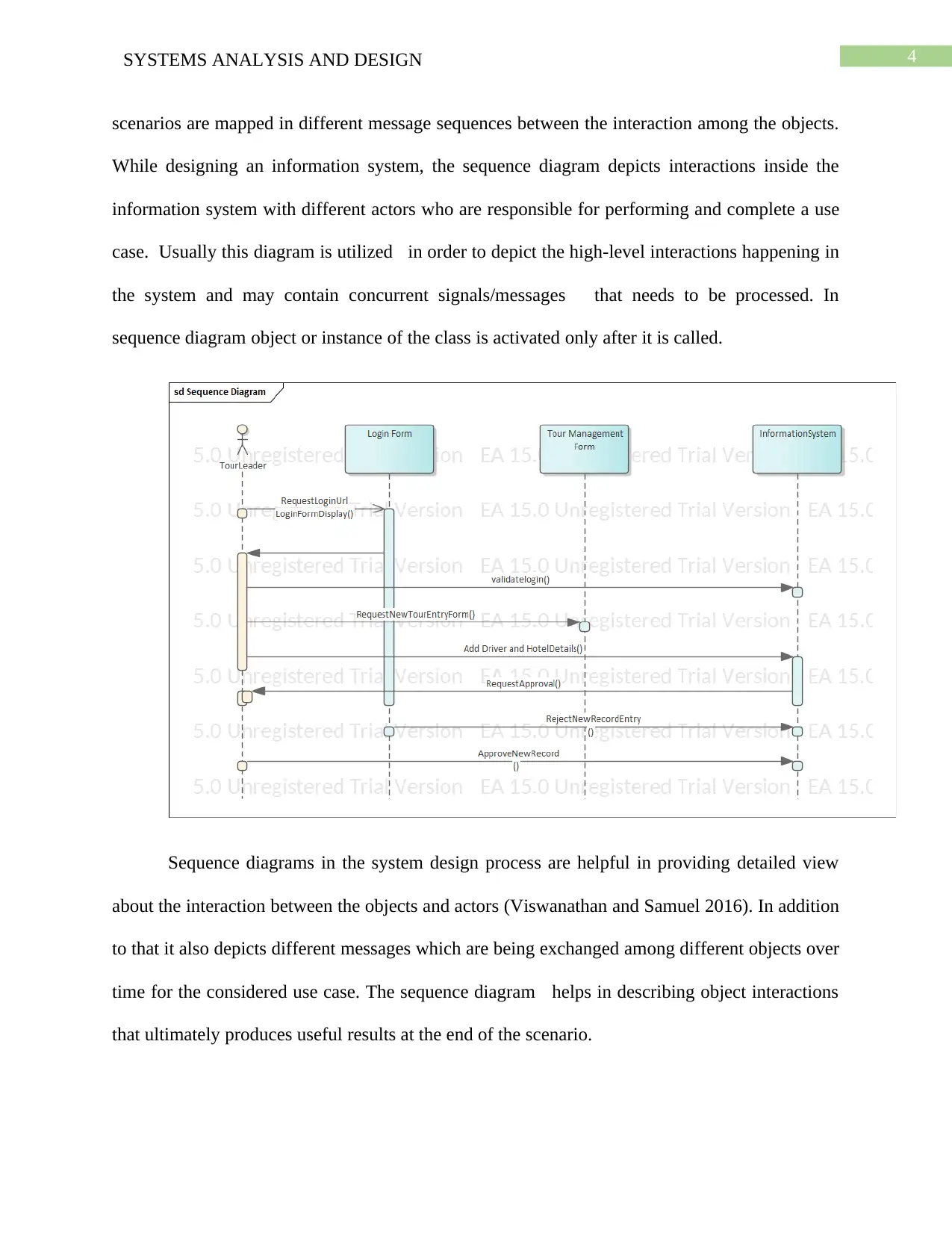
This Systems Analysis and Design assignment report delves into the application of UML diagrams and CASE tools in the context of information system development. The report is divided into three parts. Part 1 focuses on the analysis class diagram, emphasizing its importance in representing the static structure of object-oriented systems and its role in depicting classes, attributes, methods, and relationships. Part 2 examines the sequence diagram, highlighting its function in modeling interactions between objects and actors within a system, illustrating message sequences and object interactions over time. Part 3 explores the use of CASE tools in system development projects, detailing their benefits in automating software engineering activities, improving system quality, and enhancing documentation. The report also discusses the advantages of CASE tools, such as increased accuracy, reduced maintenance costs, and better documentation. The report also discusses the risks and drawbacks of CASE tools, like unrealistic client expectations and weak repository controls. The assignment is a summative coursework for the IMAT5205 module.

Running head: SYSTEMS ANALYSIS AND DESIGN
Systems Analysis and Design
Name of the Student
Name of the University
Authors note
Systems Analysis and Design
Name of the Student
Name of the University
Authors note
Paraphrase This Document
Need a fresh take? Get an instant paraphrase of this document with our AI Paraphraser

1SYSTEMS ANALYSIS AND DESIGN
Part 1
Analysis class diagram
In designing of a system, UML Class diagram are very important in order to depict
graphical representation of the different classes and instances for the object-oriented systems.
The analysis class diagram in the Unified Modeling Language depicts the static structure
diagram of the proposed information system which describes assembly of different classes and
objects inside the system by (Khan, Sengupta and Sarkar 2015).
As majority of the information system are developed in Object-oriented approach
therefore, the discovered classes, attributes of those classes, encapsulated methods as well as
relationships between classes. The class diagram is the most critical as this classes are actually
reflected in the developed information system of Wide World Coach Tours (Viswanathan and
Samuel 2016). The Class diagrams depicts static features of the proposed system while not
represent any specific processing.

2SYSTEMS ANALYSIS AND DESIGN
While designing the class diagram, the following assumptions are made most of the data
members of the classes will be declared as private so that different properties of the classes in
object-oriented approach are relevant to the design and development of the system.
The class diagram only depicts the static view of the information system.
Before the actual development the diagram will describe different responsibilities of the
proposed information system for Wide World Coach Tours.
The class diagram will be considered as the base for the different components as well as
deployment diagrams.
The class diagram will help in Forward as well as reverse engineering of the system.
Communication diagram
Communication diagram in UML is used in order to model interaction among the
different objects in the way of sequenced messages from the classes or instances of the classes.
Communication diagrams depicts mix of different information from different classes in a
sequential way that can be available from the different use case diagrams. In this way it is
possible to describe static structure as well as dynamic behavior of the proposed system
(Viswanathan and Samuel 2016). Through the communication diagram different scenarios and
objects interaction can be analyzed. The communication diagram can be considered as the
extension of any object diagram which depicts objects of the classes along with interaction
messages that is transferred from one class to another.
⊘ This is a preview!⊘
Do you want full access?
Subscribe today to unlock all pages.

Trusted by 1+ million students worldwide

3SYSTEMS ANALYSIS AND DESIGN
Assumptions made for designing the diagram
The objects will pass information only after the activation of the objects and
functionalities that are important for achieving a specific functionality.
In case of any validation control, the object or the function should wait until the
validation process is complete and Boolean output is available.
Any exception in the validation process must be managed by the instances or objects in
the system.
Part 2
Sequence Diagram
Sequence diagram in the information system development project is mainly utilized in the
identification and capture the mechanisms of the proposed system behavior. Different use-case
Paraphrase This Document
Need a fresh take? Get an instant paraphrase of this document with our AI Paraphraser

4SYSTEMS ANALYSIS AND DESIGN
scenarios are mapped in different message sequences between the interaction among the objects.
While designing an information system, the sequence diagram depicts interactions inside the
information system with different actors who are responsible for performing and complete a use
case. Usually this diagram is utilized in order to depict the high-level interactions happening in
the system and may contain concurrent signals/messages that needs to be processed. In
sequence diagram object or instance of the class is activated only after it is called.
Sequence diagrams in the system design process are helpful in providing detailed view
about the interaction between the objects and actors (Viswanathan and Samuel 2016). In addition
to that it also depicts different messages which are being exchanged among different objects over
time for the considered use case. The sequence diagram helps in describing object interactions
that ultimately produces useful results at the end of the scenario.

5SYSTEMS ANALYSIS AND DESIGN
In case of sequence diagrams, different interaction between the objects can be modeled
with different abstraction levels. Sequence diagrams illustrates different participants involved in
the interaction as well as messages in an ordered way among those objects.
Part 3
In information system development project CASE (Computer Aided System
Engineering) tool is helpful at different phases of the projects as it provides supports in multiple
software engineering activities within in the development process. Use of the CASE tools are
beneficial in improving capabilities, functionalities of the proposed system and consequently
quality of proposed information system for Wide World Coach Tours.
CASE technology is about automating the different steps involved in the software and
system development projects. Different CASE tools are characterized according to their usage
in the stages in the software development life cycle (Viswanathan and Samuel 2016). As
different tools are usable in specific stages thus it is required the tools must integrate through the
use of some central repository system.
The repository must be simultaneously accessible by project team members, clients and
other stakeholders in the project (Khan, Sengupta and Sarkar 2015). Changed versions of
requirements for the system must coexist with each other so that team members of the project
team can work in an independent way and at the end merge their specifications and developed
modules back into the main project.
CASE tools in any system development projects can be classified depending on their
support to different activities in development project. Some of the classification can be listed as
Knowledge-based CASE support, Life-cycle support, integration support for the different
⊘ This is a preview!⊘
Do you want full access?
Subscribe today to unlock all pages.

Trusted by 1+ million students worldwide

6SYSTEMS ANALYSIS AND DESIGN
modules. In addition to that, some of the other supportive tools that are used in the project are
Data flow diagram, ER diagrams, Decision tables and so on.
Even though CASE tools are considered as best in using it to make the project as an
efficient and effective software development project but there are certain risks as well as
drawbacks that can make the project a failure. This include unrealistic expectations of the clients,
weak repository controls for the project modules, inadequate standardization for the system,
slower implementation speeds.
With all the above-mentioned drawbacks, the CASE tool is capable of supporting
information system development project by automating some of the activities such as
determining the interactions among the objects, enabling flow of information about the proposed
system being developed and so on. Following are the some of the most important advantages
provided by CASE tools.
Increased Accuracy in the project
CASE Tools are helpful in providing simultaneous debugging as well as error checking
in the developed modules for the system that is considered as very important in early defect
elimination from the modules that takes too much time in detection and rectification and plays a
major role in information system development project (Khan, Sengupta and Sarkar 2015).
In case developing an information system, defect removal in the early stages is
considered as important as in the later stages it takes too much time and effort to detect the issues
and rectify them. Lesser amount of effort and time is required if corrections to the defects are
made in the early stages (as an example in design stages). As with the different iterations of the
development the system grows bigger that causes difficult to modify the modules and complete
Paraphrase This Document
Need a fresh take? Get an instant paraphrase of this document with our AI Paraphraser

7SYSTEMS ANALYSIS AND DESIGN
system. in the later stages the error identification in the modules becomes a complex issue. In
some of the scenarios restraining the development is also involved which leads to incurring the
huge cost, time and finally effort of the project team. Even the management and communicating
the issues in the bigger teams seems difficult in terms of time consumption and cost.
Reduced Lifetime Maintenance
Due to the enhanced design, analysis process, automatic code generation, testing process,
overall quality of the system improves in each iteration. In this way it is also possible to better
manage the documentation process. Therefore, the effort as well as cost incurred in the
maintenance is reduced in the complete life time of the project (Viswanathan and Samuel 2016).
In addition to that, available extra resources can be utilized in refining the different other
functions in the development process. The CASE tool provides different reengineering tools
which are considered as important in improving the quality as they make the complete process
more efficient with lesser time consumption as well as less expensive.
Better Documentation
While using CASE Tools it is also possible to carry out the huge amount of
documentation for the system along way with the development. Most of the tools of the CASE
tools contains revision for comments as well as notes on the development as well as
maintenance. System documentation is always considered as a huge problem in the projects
where CASE tools are not used. In most of the projects the documentation remains labor-
intensive, incomplete, human error-prone. Use of the CASE tools is capable of completely
changing the process of generating documentation for the proposed system from a manual one to
automated one.

8SYSTEMS ANALYSIS AND DESIGN
Every time a new system developed implementation stage integrates multiple related but
different tasks. In this stage different processes must be efficiently organized which can be easily
done by the CASE tools. By using CASE tools integration process can be automated and
efficiently organized in the life cycle of the project.
⊘ This is a preview!⊘
Do you want full access?
Subscribe today to unlock all pages.

Trusted by 1+ million students worldwide

9SYSTEMS ANALYSIS AND DESIGN
References
Bhullar, N.S., Chhabra, B. and Verma, A., 2016, August. Exploration of UML diagrams based
code generation methods. In 2016 International Conference on Inventive Computation
Technologies (ICICT) (Vol. 2, pp. 1-6). IEEE.
Khan, G., Sengupta, S. and Sarkar, A., 2015, March. Modeling of services and their
collaboration in enterprise cloud bus (ECB) using UML 2.0. In 2015 International Conference
on Advances in Computer Engineering and Applications (pp. 207-213). IEEE.
Mouheb, D., Debbabi, M., Pourzandi, M., Wang, L., Nouh, M., Ziarati, R., Alhadidi, D., Talhi,
C. and Lima, V., 2015. Unified Modeling Language. In Aspect-Oriented Security Hardening of
UML Design Models (pp. 11-22). Springer, Cham.
Sarkar, D., Bhalla, M. and Singal, S.M., 2017, January. Enhancing unified process workflows
using UML. In 2017 7th International Conference on Cloud Computing, Data Science &
Engineering-Confluence (pp. 788-792). IEEE.
Torre, D., 2016, October. Verifying the consistency of UML models. In 2016 IEEE
International Symposium on Software Reliability Engineering Workshops (ISSREW) (pp. 53-54).
IEEE.
Viswanathan, S.E. and Samuel, P., 2016. Automatic code generation using unified modeling
language activity and sequence models. IET Software, 10(6), pp.164-172.
1 out of 10
Related Documents

Your All-in-One AI-Powered Toolkit for Academic Success.
+13062052269
info@desklib.com
Available 24*7 on WhatsApp / Email
Unlock your academic potential
Copyright © 2020–2025 A2Z Services. All Rights Reserved. Developed and managed by ZUCOL.