IMAT5205 Systems Analysis and Design: Assignment 2 - Modelling Report
VerifiedAdded on 2022/09/06
|13
|1691
|29
Report
AI Summary
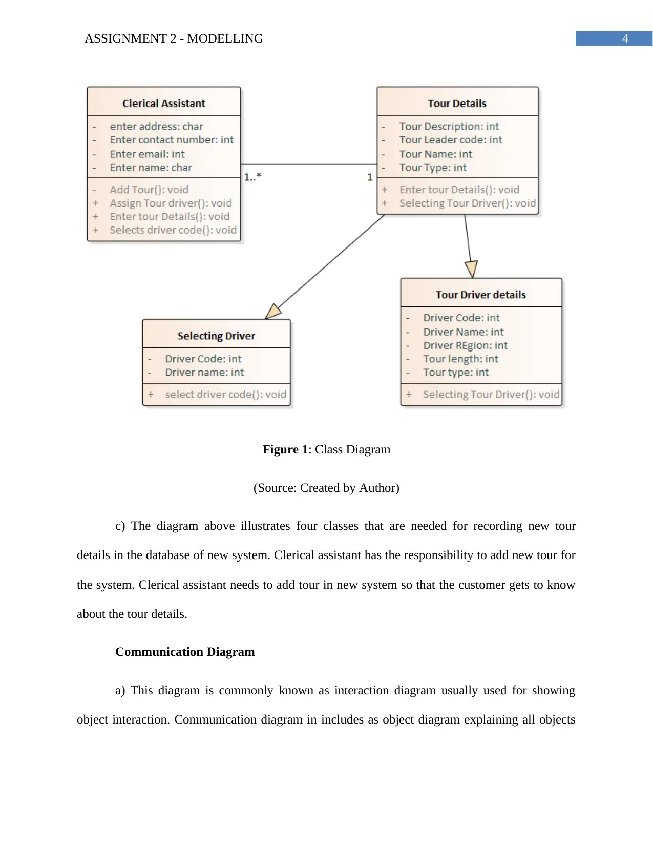
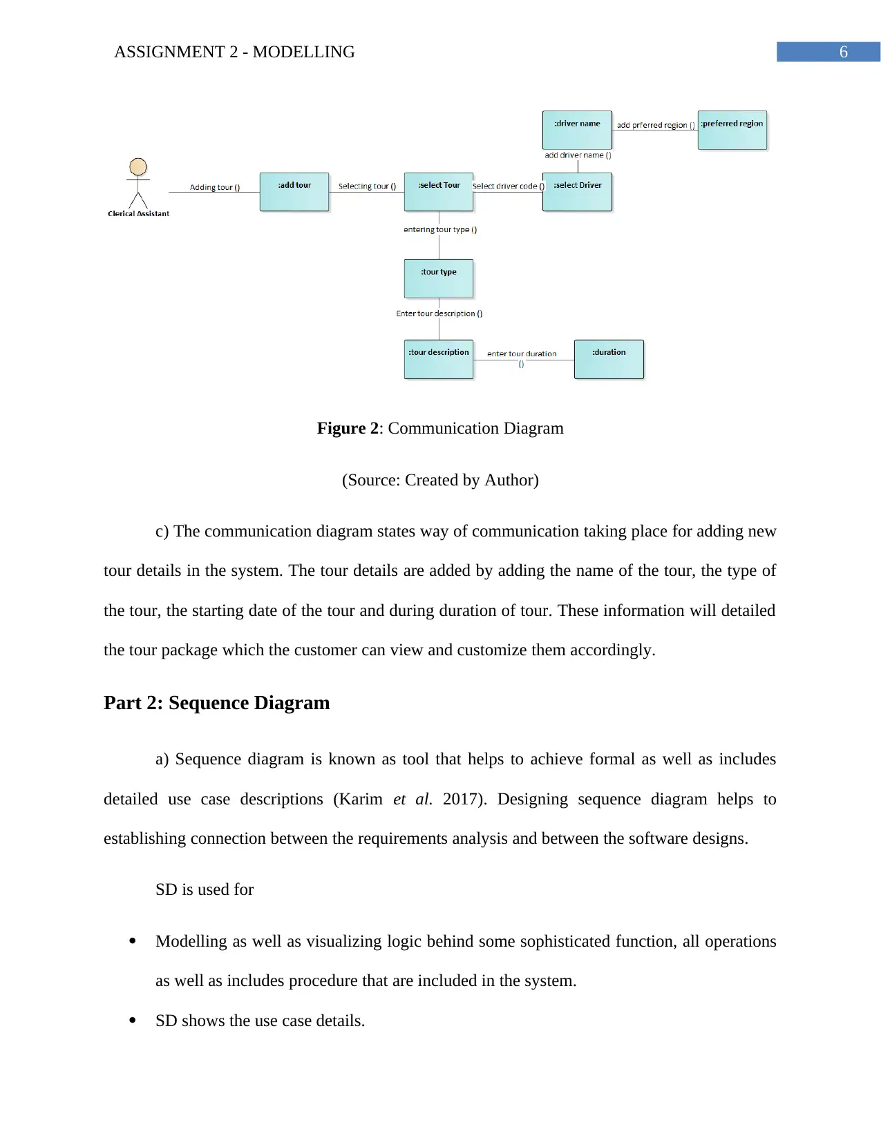
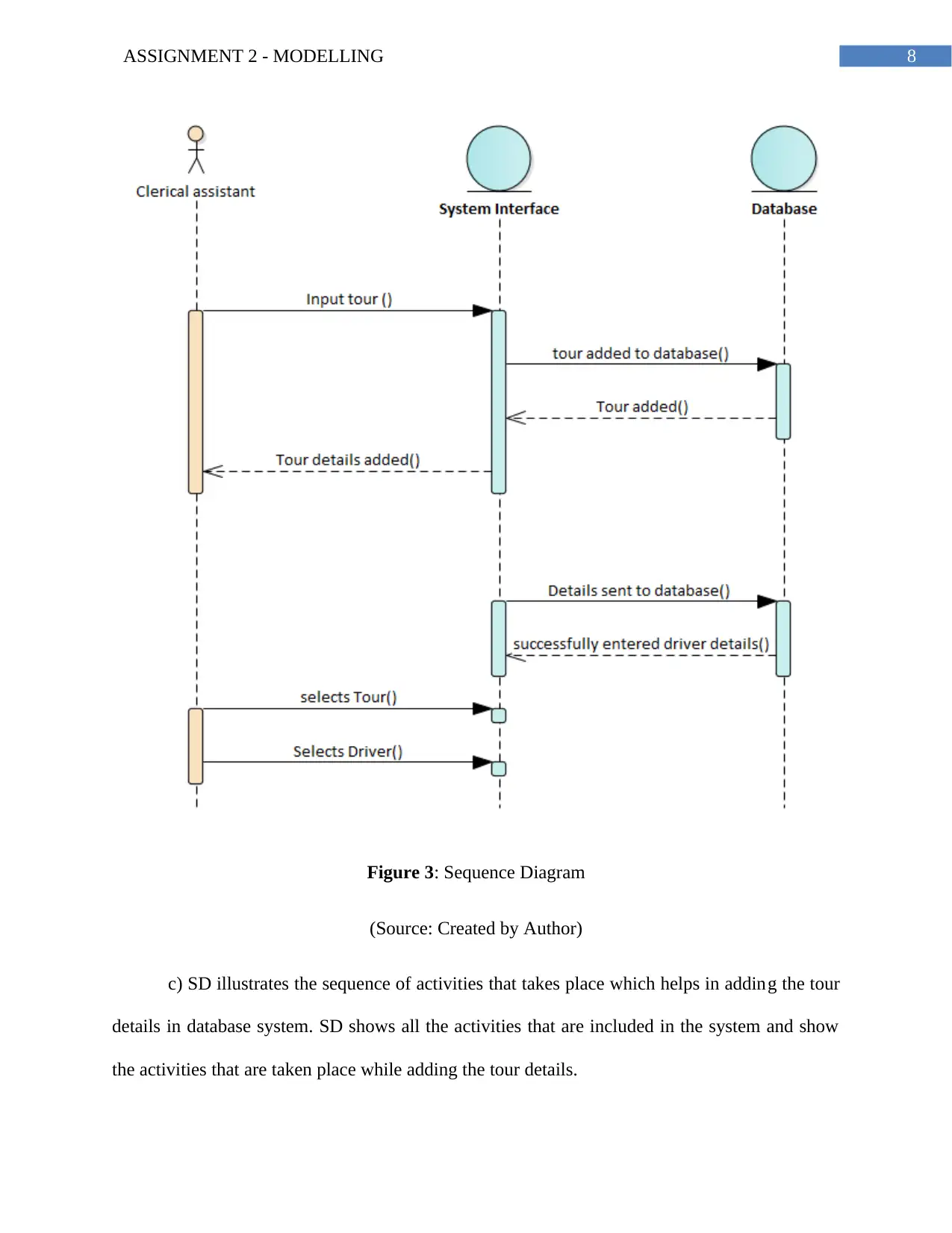
This report presents a detailed analysis of a systems analysis and design assignment, focusing on the 'Record New Tour' use case. The assignment includes the creation and explanation of a Class Diagram, demonstrating the static structure of the system, and a Communication Diagram, illustrating object interactions and message passing. A Sequence Diagram is also provided, outlining the sequence of activities involved in adding tour details to a database. The report concludes with an evaluation of CASE (Computer-Aided Software Engineering) tools, discussing their role in software development, including their benefits in reducing development time and cost, enhancing software quality, and supporting various stages of the software development life cycle. The report references various research papers and journals to support the findings and methodologies used.

Running head: ASSIGNMENT 2 - MODELLING
System Analysis and Design
Name of Student-
Name of University-
Author’s Note-
System Analysis and Design
Name of Student-
Name of University-
Author’s Note-
Secure Best Marks with AI Grader
Need help grading? Try our AI Grader for instant feedback on your assignments.

1ASSIGNMENT 2 - MODELLING
Table of Contents
Part 1: Use Case Realization for ‘Record New Tour’ Use Case.....................................................1
Part 2: Sequence Diagram...............................................................................................................4
Part 3: Evaluation............................................................................................................................6
Bibliography....................................................................................................................................8

2ASSIGNMENT 2 - MODELLING
Part 1: Use Case Realization for ‘Record New Tour’ Use Case
Analysis Class Diagram
a) CD can be defined as static structure diagram that help in describing the system
structure (Mathur and Kaushik 2018). Class diagram demonstrates the classes, the attributes
related to classes, the operations or the methods that are used for the system and establish
relationship among all the classes in the system.
The main purpose of CD in system in system analysis and design are:
Showing the static structure of the classifiers in the system.
CD provides some basic notation basically used for structured diagrams used in the UML
diagrams.
The UML diagram are helpful for all developers as well as for other team members
associated with the system (Huang et al. 2016).
b) Class Diagram

3ASSIGNMENT 2 - MODELLING
Secure Best Marks with AI Grader
Need help grading? Try our AI Grader for instant feedback on your assignments.

4ASSIGNMENT 2 - MODELLING
Figure 1: Class Diagram
(Source: Created by Author)
c) The diagram above illustrates four classes that are needed for recording new tour
details in the database of new system. Clerical assistant has the responsibility to add new tour for
the system. Clerical assistant needs to add tour in new system so that the customer gets to know
about the tour details.
Communication Diagram
a) This diagram is commonly known as interaction diagram usually used for showing
object interaction. Communication diagram in includes as object diagram explaining all objects

5ASSIGNMENT 2 - MODELLING
with messages that travels from one object to another object (Miyamoto 2017). Along with the
associations, interaction between objects through messages are also shown in this diagram.
There are certain purpose included communication diagram is
This diagram models includes message that transfers the message between the objects
and all roles included in communication diagram states the functionalities of operations
(Belghiat, Chaoui and Beldjehem 2015).
This diagram models mechanism within architectural design within the system.
This diagram captures interaction that helps in showing message passing between all
objects.
b) Communication Diagram

6ASSIGNMENT 2 - MODELLING
Figure 2: Communication Diagram
(Source: Created by Author)
c) The communication diagram states way of communication taking place for adding new
tour details in the system. The tour details are added by adding the name of the tour, the type of
the tour, the starting date of the tour and during duration of tour. These information will detailed
the tour package which the customer can view and customize them accordingly.
Part 2: Sequence Diagram
a) Sequence diagram is known as tool that helps to achieve formal as well as includes
detailed use case descriptions (Karim et al. 2017). Designing sequence diagram helps to
establishing connection between the requirements analysis and between the software designs.
SD is used for
Modelling as well as visualizing logic behind some sophisticated function, all operations
as well as includes procedure that are included in the system.
SD shows the use case details.
Paraphrase This Document
Need a fresh take? Get an instant paraphrase of this document with our AI Paraphraser

7ASSIGNMENT 2 - MODELLING
SD is used for understanding detailed functionality that are used in the current system
(Sellami et al. 2015).
This diagram helps to visualize the way in which messages as well as tasks moves
between the objects or between the components that are included in the system.
b) Sequence Diagram
SD is used for understanding detailed functionality that are used in the current system
(Sellami et al. 2015).
This diagram helps to visualize the way in which messages as well as tasks moves
between the objects or between the components that are included in the system.
b) Sequence Diagram

8ASSIGNMENT 2 - MODELLING
Figure 3: Sequence Diagram
(Source: Created by Author)
c) SD illustrates the sequence of activities that takes place which helps in adding the tour
details in database system. SD shows all the activities that are included in the system and show
the activities that are taken place while adding the tour details.

9ASSIGNMENT 2 - MODELLING
Part 3: Evaluation
Case tools are basically automated assistance for developing new software. The main
goal for introducing the CASE tools is reducing the total time and the total cost that is used for
developing the software. This Case tools also helps to enhance total quality of system that is to
be developed. The main interest of this tool is actually based on the expectation of the client and
helps to increase the productivity (Skersys, Pavalkis and Nemuraite 2015). The tool also helps to
improve the quality of the product, facilitating the maintenance, as well as helps to make the task
of software engineers easier. Case tool mainly supports computer based programs that helps to
develop the process. This tool support more than one software engineering activities for
developing the software.
The case environment includes collection of the case tools as well as other components
with interaction approach along with the supporting more engineering activities to develop a
system. The Case tools includes different products along with different functionalities. The tools
and methods helps in supporting all engineering approach for developing all stages for the
system process. The Case tool includes software application programs includes automate SDLC
activities and are mainly used by the software project managers, system analysts as well as
system engineers.
The case tool is engineering tools that helps in permitting software development
collaboration as well as maintenance for the project. All phases included in developing the
software are supported by system analysis and system design (Sassi,Jedidi and Fourati 2019).
The standard method of software development includes Jackson Structure Programming or
includes structured system analysis. The Case tools also include system design for developing
Secure Best Marks with AI Grader
Need help grading? Try our AI Grader for instant feedback on your assignments.

10ASSIGNMENT 2 - MODELLING
the software. The installation process is automated as well as coordinated with the Case tool and
is developed within the system life cycle.
The tasks in Case tools are creating the data flow as well as the entity models while
developing the system. This tool also includes establishing relationship between the models as
well as the requirements, helps to develop a top level design, develop functional as well as
process description in the system. The case tool includes development of the test cases. For
analyzing the World Wide scenario, the Case tool has helped to facilitate single methodology of
design. This tool has also improved rapid development of application. This has helped to reduce
the cost of the development.
The case tools used by the system analyst helps to improve their routine work with the
use of automated support (Kopylova and Maklakova 2018). This tool helps to increase the
productivity, helps to communicate more effectively with the users as well as helps to integrate
all work as they do with the system from beginning of the software development. There is visible
analysts that helps the analysts to do the graphical planning, build the server applications and
their related databases.
The UML modelling helps to model the system with interdependent platform language.
UML is graphical language that helps in visualizing the system, specify the system, constructing
as well as documenting the information that are included in the system.

11ASSIGNMENT 2 - MODELLING
Bibliography
Belghiat, A., Chaoui, A. and Beldjehem, M., 2015, August. Capturing and verifying dynamic
program behaviour using UML communication diagrams and pi-calculus. In 2015 IEEE
International Conference on Information Reuse and Integration (pp. 318-325). IEEE.
Huang, L., Duan, Y., Sun, X., Lin, Z. and Zhu, C., 2016, October. Enhancing UML Class
Diagram Abstraction with Knowledge Graph. In International Conference on Intelligent Data
Engineering and Automated Learning (pp. 606-616). Springer, Cham.
Ibrahim, R., Aman, H., Nayak, R. and Jamel, S., 2018. Consistency Check between XML
Schema and Class Diagram for Document Versioning. International Journal on Advanced
Science, Engineering and Information Technology, 8(6), pp.2590-2597.
Karim, S., Liawatimena, S., Trisetyarso, A., Abbas, B.S. and Suparta, W., 2017, November.
Automating functional and structural software size measurement based on XML structure of
UML sequence diagram. In 2017 IEEE International Conference on Cybernetics and
Computational Intelligence (CyberneticsCom) (pp. 24-28). IEEE.
Kopylova, V.S. and Maklakova, E.A., 2018. Computer-Aided Software Engineering.
In Актуальные проблемы современной науки (pp. 71-75).
Mathur, B. and Kaushik, M., 2016. Empirical Analysis of Metrics Using UML Class
Diagram. International Journal of Advanced Computer Science and Applications (IJACSA), 7(5),
pp.32-37.

12ASSIGNMENT 2 - MODELLING
Miyamoto, T., 2017. Synthesizing Pareto efficient intelligible state machines from
communication diagram. IEICE TRANSACTIONS on Information and Systems, 100(6), pp.1200-
1209.
SASSI, M.S.H., JEDIDI, F.G. and FOURATI, L.C., 2019, June. Computer-Aided Software
Engineering (CASE) Tool for Big Data and IoT Architecture. In 2019 15th International
Wireless Communications & Mobile Computing Conference (IWCMC) (pp. 1403-1410). IEEE.
Sellami, A., Hakim, H., Abran, A. and Ben-Abdallah, H., 2015. A measurement method for
sizing the structure of UML sequence diagrams. Information and Software Technology, 59,
pp.222-232.
Skersys, T., Pavalkis, S. and Nemuraite, L., 2015, March. Implementing semantically rich
business vocabularies in CASE tools. In AIP Conference Proceedings (Vol. 1648, No. 1, p.
310002). AIP Publishing.
1 out of 13
Related Documents

Your All-in-One AI-Powered Toolkit for Academic Success.
+13062052269
info@desklib.com
Available 24*7 on WhatsApp / Email
Unlock your academic potential
© 2024 | Zucol Services PVT LTD | All rights reserved.