ICT103 Systems Analysis and Design: Hotel Booking System Diagrams
VerifiedAdded on 2022/08/21
|23
|2433
|27
Homework Assignment
AI Summary
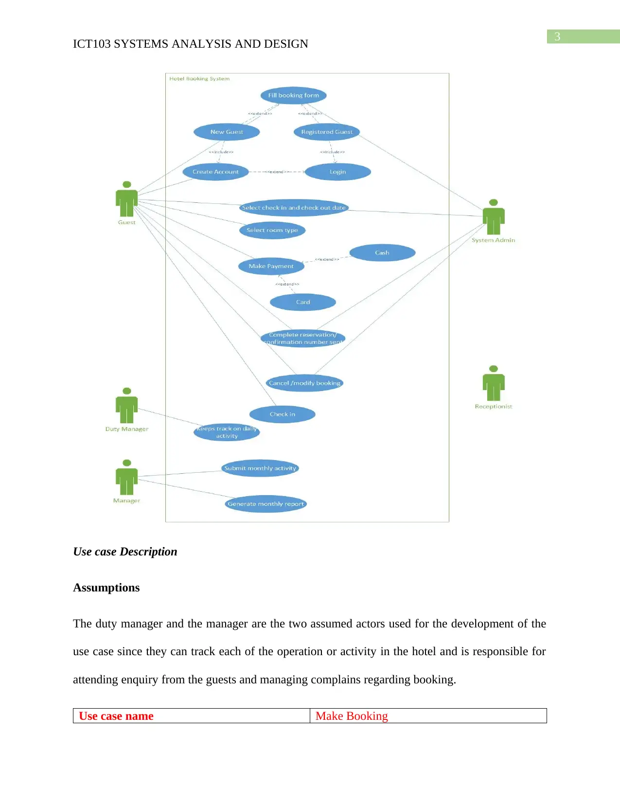
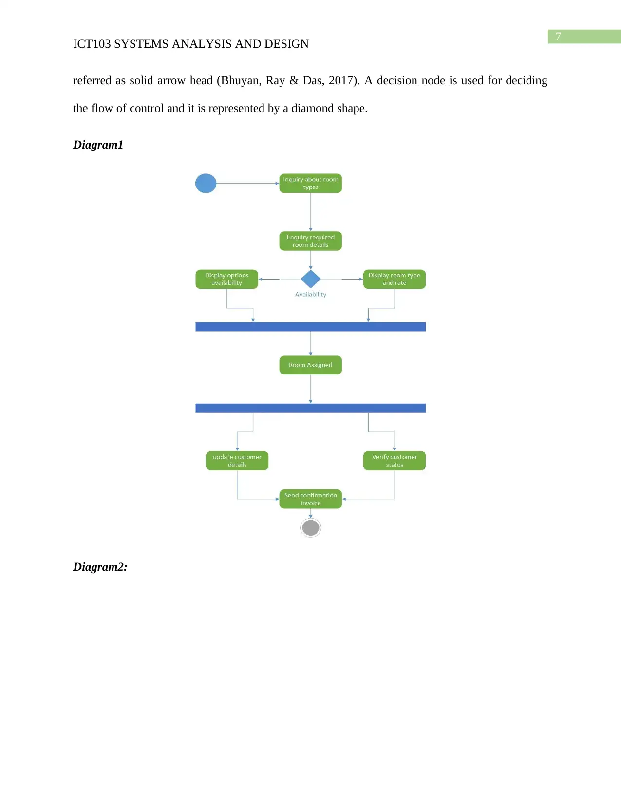
This assignment solution for ICT103 Systems Analysis and Design details the creation of various UML diagrams to model a hotel booking system. It begins with use cases, illustrating interactions between users and the system, including actors, associations, and descriptions of scenarios like making a booking. Activity diagrams are then presented, showcasing the workflow and control flow within the system. Sequence diagrams visualize the interactions between objects over time, depicting message flows for key functionalities. The solution also includes a domain model class diagram, representing the system's objects and their relationships. Furthermore, state machine diagrams are provided to visualize the system's states and transitions. Finally, the assignment covers user interface design, employing Balsamic mockup to demonstrate different layers of the proposed booking system, along with considerations for device compatibility and user experience. The document concludes with a summary of the analysis and design process, emphasizing the use of UML diagrams for gathering requirements and developing the information system.

Running head: ICT103 SYSTEMS ANALYSIS AND DESIGN
ICT103 Systems Analysis and Design
Name of the Student
Name of the University
Author’s Note
ICT103 Systems Analysis and Design
Name of the Student
Name of the University
Author’s Note
Paraphrase This Document
Need a fresh take? Get an instant paraphrase of this document with our AI Paraphraser

1
ICT103 SYSTEMS ANALYSIS AND DESIGN
Table of Contents
Use cases..........................................................................................................................................2
Activity Diagrams............................................................................................................................6
Sequence Diagrams.........................................................................................................................9
Domain Model Class Diagram......................................................................................................12
State Machine Diagram.................................................................................................................14
User Interface.................................................................................................................................16
Conclusion.....................................................................................................................................19
Bibliography..................................................................................................................................21

2
ICT103 SYSTEMS ANALYSIS AND DESIGN
Use cases
It is used for demonstrating the interaction between the hotel booking system and the
users for the achievement of the goals of the user. The activity performed by each of the actor
associated with the information system is shown and here the most important elements are the
use case and the actors (Jacobson, Spence & Kerr, 2016).
Basic Elements of the Model
Actor: A role is represented by the actor who directly interacts with the information system.
Association: The association is used for describing the relationship between the use case and the
actor
Use Case: The use case shows the functionality of working of the system and the interaction
between the system and the actor.
⊘ This is a preview!⊘
Do you want full access?
Subscribe today to unlock all pages.

Trusted by 1+ million students worldwide

3
ICT103 SYSTEMS ANALYSIS AND DESIGN
Use case Description
Assumptions
The duty manager and the manager are the two assumed actors used for the development of the
use case since they can track each of the operation or activity in the hotel and is responsible for
attending enquiry from the guests and managing complains regarding booking.
Use case name Make Booking
Paraphrase This Document
Need a fresh take? Get an instant paraphrase of this document with our AI Paraphraser

4
ICT103 SYSTEMS ANALYSIS AND DESIGN
Scenario Displaying available room and their rates per
night
Triggering event Searching availability of the room using the
option of check out and check in
Brief description: Displaying available room and their rates per
night
Actors: Receptionist, Guest/Customer
Related Use cases: Updating the details of booking and
displaying the new details of booking
Stakeholders Customer, system admin
Preconditions Modification of booking with the use of
booking number
Post conditions Confirmation of the payment and sending the
confirmation via mobile/email
Name of Use case Login
Actor Customer, Receptionist, manager and System
Admin
Description An authorized username and password is
entered by the user for accessing the system
Basic Action Actor System Response
Opening the login Displaying the login

5
ICT103 SYSTEMS ANALYSIS AND DESIGN
page page to be filled by
the user for
authorization
Enter login
credentials and click
the login button
A search is made on
the information
system for matching
username and
password
Ending use case If the username and
password matches the
user is redirected to
the next page or error
message is displayed
Name of Use case Select Room Type
Actor Customer, Receptionist, manager and System
Admin
Description The room type is checked by searching the
database
Flow of activities User Action System Response
Selection of room
type from available
room
Displaying the types
of room categorized
into the interface
⊘ This is a preview!⊘
Do you want full access?
Subscribe today to unlock all pages.

Trusted by 1+ million students worldwide

6
ICT103 SYSTEMS ANALYSIS AND DESIGN
Searching room type
from home page
A search is made on
the information
system for matching
type of room
Ending use case If the search keyword
matches the available
room types are
displayed or an error
message is displayed
Activity Diagrams
The control flow is represented by the activity diagram for the hotel booking system and
it refers to the steps that are included for executing the use case. A model is created for the
concurrent and sequence activity with the help of activity diagram and thus workflow is depicted
visually. The message flow condition is focused for finding the result and finding the root cause
of the event. A starting and finishing point is used for the demonstration of decision paths for the
execution of the activity. The dynamic aspects of the system can be shown with the help of the
activity diagram and is very similar with the flowchart (Kamath & Narendra, 2018). It can be
used for decision making and understand the flow of program for high level. The constraint can
be figured out along with the constraint and condition causing the particular event and it can also
converge the flow chart for converging the activity diagram in case of taking complex decision.
The activity is represented by a rounded corner rectangular box and the flow of control is
Paraphrase This Document
Need a fresh take? Get an instant paraphrase of this document with our AI Paraphraser

7
ICT103 SYSTEMS ANALYSIS AND DESIGN
referred as solid arrow head (Bhuyan, Ray & Das, 2017). A decision node is used for deciding
the flow of control and it is represented by a diamond shape.
Diagram1
Diagram2:
ICT103 SYSTEMS ANALYSIS AND DESIGN
referred as solid arrow head (Bhuyan, Ray & Das, 2017). A decision node is used for deciding
the flow of control and it is represented by a diamond shape.
Diagram1
Diagram2:

8
ICT103 SYSTEMS ANALYSIS AND DESIGN
Diagram3:
ICT103 SYSTEMS ANALYSIS AND DESIGN
Diagram3:
⊘ This is a preview!⊘
Do you want full access?
Subscribe today to unlock all pages.

Trusted by 1+ million students worldwide

9
ICT103 SYSTEMS ANALYSIS AND DESIGN
Sequence Diagrams
The sequence diagram is used as a modelling language used for standardizing and
visualizing the system design. It can be used as an interaction diagram and demonstrates the
interactive behavior of the system. The objects are depicted in a sequential manner as the
interaction takes places. The sequence starts from the actor and it represents the role for its
interaction with the objects of the system. Solid arrow is used for the representation of flow of
message between the messages (Muñoz et al., 2019). The messages can be synchronous i.e. they
waits for the reply before moving forward to the new interaction. The sender of the message
needs to wait until receiver completes processing of the messages until the reply message is
received. The receiver sends the reply message to the sender and it is represented by dotted line
and open arrow head. The sequence diagram finds its application in modelling and visualizing
the logic for a function procedure or operation (Zhao, Payne & Atkison, 2018). They also
demonstrates the details of the use case diagram and understand the functionality in details of the
hotel booking system. The message and the flow of task between objects are also visualized by
the diagram.
Diagram1:
Paraphrase This Document
Need a fresh take? Get an instant paraphrase of this document with our AI Paraphraser

10
ICT103 SYSTEMS ANALYSIS AND DESIGN
Diagram2:
ICT103 SYSTEMS ANALYSIS AND DESIGN
Diagram2:

11
ICT103 SYSTEMS ANALYSIS AND DESIGN
Diagram3:
ICT103 SYSTEMS ANALYSIS AND DESIGN
Diagram3:
⊘ This is a preview!⊘
Do you want full access?
Subscribe today to unlock all pages.

Trusted by 1+ million students worldwide
1 out of 23
Related Documents

Your All-in-One AI-Powered Toolkit for Academic Success.
+13062052269
info@desklib.com
Available 24*7 on WhatsApp / Email
Unlock your academic potential
Copyright © 2020–2025 A2Z Services. All Rights Reserved. Developed and managed by ZUCOL.