Modeling for Systems Analysis and Design Assignment 2: IMAT5205 Report
VerifiedAdded on 2022/09/09
|9
|1767
|11
Report
AI Summary
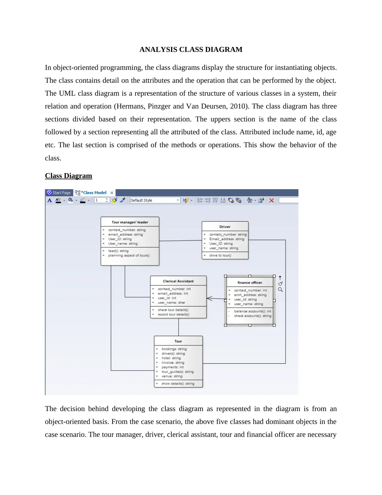
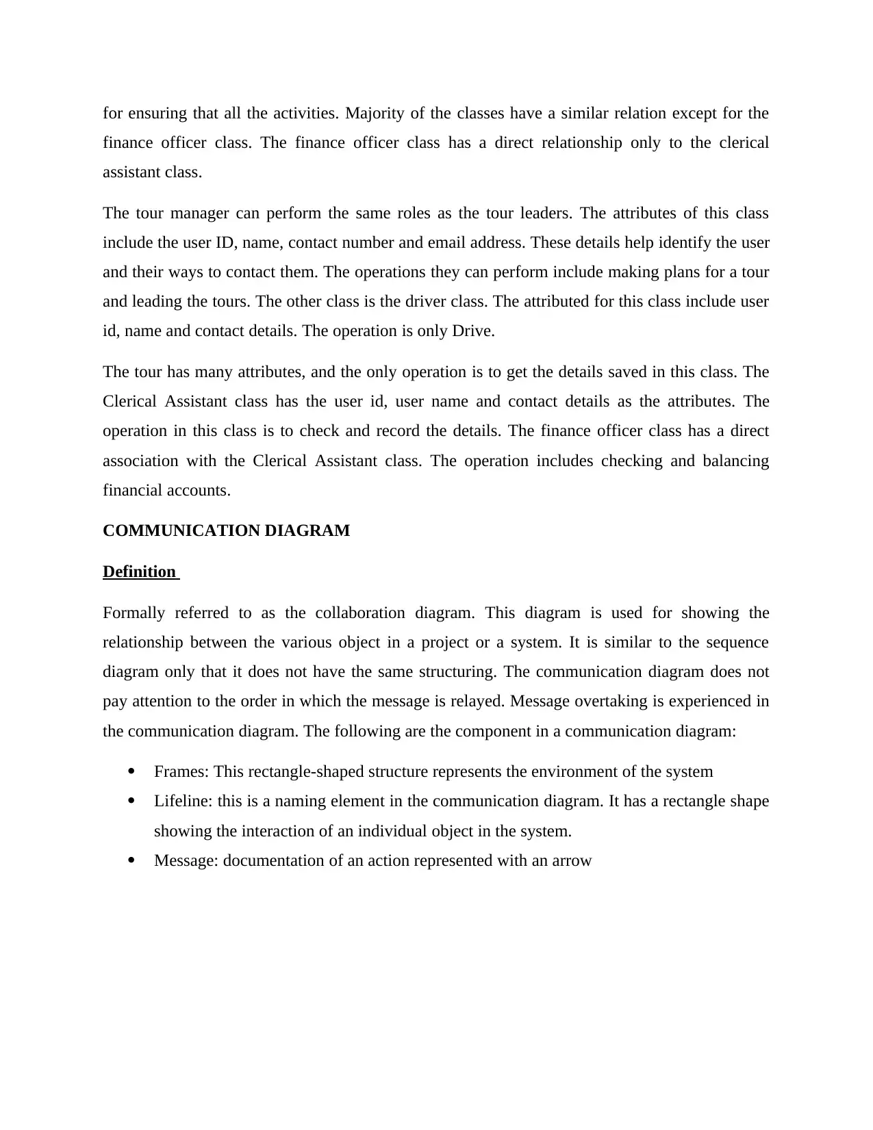
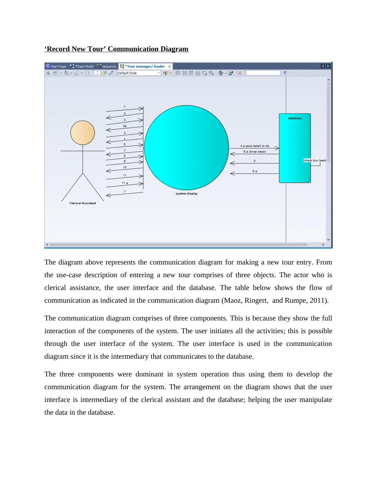
This report provides an in-depth analysis of systems modeling techniques, focusing on class diagrams, communication diagrams, and sequence diagrams within the context of object-oriented programming. It details the structure, attributes, and operations of classes, illustrating their relationships an...

ANALYSIS CLASS DIAGRAM
In object-oriented programming, the class diagrams display the structure for instantiating objects.
The class contains detail on the attributes and the operation that can be performed by the object.
The UML class diagram is a representation of the structure of various classes in a system, their
relation and operation (Hermans, Pinzger and Van Deursen, 2010). The class diagram has three
sections divided based on their representation. The uppers section is the name of the class
followed by a section representing all the attributed of the class. Attributed include name, id, age
etc. The last section is comprised of the methods or operations. This show the behavior of the
class.
Class Diagram
The decision behind developing the class diagram as represented in the diagram is from an
object-oriented basis. From the case scenario, the above five classes had dominant objects in the
case scenario. The tour manager, driver, clerical assistant, tour and financial officer are necessary
Paraphrase This Document
Need a fresh take? Get an instant paraphrase of this document with our AI Paraphraser

for ensuring that all the activities. Majority of the classes have a similar relation except for the
finance officer class. The finance officer class has a direct relationship only to the clerical
assistant class.
The tour manager can perform the same roles as the tour leaders. The attributes of this class
include the user ID, name, contact number and email address. These details help identify the user
and their ways to contact them. The operations they can perform include making plans for a tour
and leading the tours. The other class is the driver class. The attributed for this class include user
id, name and contact details. The operation is only Drive.
The tour has many attributes, and the only operation is to get the details saved in this class. The
Clerical Assistant class has the user id, user name and contact details as the attributes. The
operation in this class is to check and record the details. The finance officer class has a direct
association with the Clerical Assistant class. The operation includes checking and balancing
financial accounts.
COMMUNICATION DIAGRAM
Definition
Formally referred to as the collaboration diagram. This diagram is used for showing the
relationship between the various object in a project or a system. It is similar to the sequence
diagram only that it does not have the same structuring. The communication diagram does not
pay attention to the order in which the message is relayed. Message overtaking is experienced in
the communication diagram. The following are the component in a communication diagram:
Frames: This rectangle-shaped structure represents the environment of the system
Lifeline: this is a naming element in the communication diagram. It has a rectangle shape
showing the interaction of an individual object in the system.
Message: documentation of an action represented with an arrow

‘Record New Tour’ Communication Diagram
The diagram above represents the communication diagram for making a new tour entry. From
the use-case description of entering a new tour comprises of three objects. The actor who is
clerical assistance, the user interface and the database. The table below shows the flow of
communication as indicated in the communication diagram (Maoz, Ringert, and Rumpe, 2011).
The communication diagram comprises of three components. This is because they show the full
interaction of the components of the system. The user initiates all the activities; this is possible
through the user interface of the system. The user interface is used in the communication
diagram since it is the intermediary that communicates to the database.
The three components were dominant in system operation thus using them to develop the
communication diagram for the system. The arrangement on the diagram shows that the user
interface is intermediary of the clerical assistant and the database; helping the user manipulate
the data in the database.
⊘ This is a preview!⊘
Do you want full access?
Subscribe today to unlock all pages.

Trusted by 1+ million students worldwide

SEQUENCE DIAGRAM
Definition
This is similar to the communication diagram (Swain, Mohapatra, and Mall, 2010). The
sequence diagram shows the relation between the various objects in an orderly manner. Some
may refer to the sequence diagram as an event diagram. A system can have several sequence
diagram each showing a complete process from the start to the stop. The sequence diagram is
made up of objects and lifeline vertically below the objects. Communication from an object
triggers the start of a lifeline. An arrow represents communication between the various object.
An additional text on the arrows describes the actions. The sequence diagram makes use of the
synchronous message; it waits for an interaction of the object before reply to a message.
Sequence Diagram
Paraphrase This Document
Need a fresh take? Get an instant paraphrase of this document with our AI Paraphraser

The sequence diagram has similar characteristics to the communication diagram of the system.
This characteristic was the reason for having three components in the sequence diagram. The
sequence diagram differs from the communication diagram since it has to have a sequence of
information flow. Clerical assistance is the initiator of the activities. The user interface allows the
clerical assistance to interact with the database.
The three components in the diagram have sequential lifelines. Once information flows from one
object to the other, the lifeline pauses until it receives information. This illustrates the flow of
activities. The use of unidirectional lines in the diagram is significant in showing the direction of
information. The arrowhead showing the direction in which communication is flowing.

CASE Tool EVALUATION
A CASE tool is an abbreviation of the Computer-Aided Software Engineer. The CASE tools are
computer tools that help software engineering in designing and developing software. It helps the
software engineers to automate and simulate some of the processes. The major application of the
CASE tools include:
Specification of requirements
Structure analysis
Designing
Coding
Testing
Simulation
Some of the specialized operations that do not involve phase activities such as system
configuration and project management. The functionality that a CASE tool brings to system
development includes increased productivity and quality of the system.
Three levels can be used in categorizing the CASE tools. These include:
Upper CASE tools are important in system design
Lower CASE tools- help in coding the system
Integrated CASE tools- also referred to the I-CASE tool. They support all the design and
development phases.
The following are the reasons for using CASE tools in system design and development of the
World-Wide tour system:
i. It saves the time and financial resources invested in designing and developing a system
ii. Better error avoidance
iii. Better error identification
iv. Increases the productivity
v. Reducing the maintenance cost
vi. Better software production
⊘ This is a preview!⊘
Do you want full access?
Subscribe today to unlock all pages.

Trusted by 1+ million students worldwide

Enterprise Architect is one of the popular CASE tools that are free to download. The tool has to
be purchased but has a free day trial for the designer to interact with the system before they get
to purchase it. Spark Systems developed the Enterprise Architect software as an integrated
modelling for the following applications:
i. System development and design
ii. Real-time development
iii. Maintain business systems
The system is comprised of management utilities and functionalities that help in performing
complex development, designing, maintaining and testing models. These models can be BPMN,
UML and SysML.
Enterprise also has a high-performance feature that makes it effective. It is suitable for loading
extremely large models within the smallest time as compared to other CASE tools (Grimes and
Warschauer, 2010). Teams can also access the models simultaneously without any slack in time.
The simulation functionality of the. One of these is the use of dynamic model simulation that
brings the models to life. This aspect makes it possible to comprehend the structure and
behavior. The control structure gives the software designer more control in running and
developing the system models. The control feature given to the designer will let them in
performing multiple operations. This makes it possible to use the optimum analysis to identify
the best variable and conditions to develop a high-quality system.
Tractability is another element that makes the Enterprise Architect suitable for designing and
developing systems. One can access their project easily through the panels on its user interface.
The Enterprise Architect CASE tool has an elaborate documentation system that helps in
defining the model.
Despite the additional useful functionalities incorporated in the CASE tool, the most dominant
utility for the developer and system designers is the source code roundtrip. This built-in
functionality makes it possible to model the system directly to its source code. The system is
compatible with most of the programming languages. These include Ada, C, C++, Java, Python,
Delphi, ActionScript, Verilog, PHP, VHDL, VB.Net, Visual Basic and System C.
Paraphrase This Document
Need a fresh take? Get an instant paraphrase of this document with our AI Paraphraser

From the above information, it is evident that the Enterprise Architect has functionalities and
software resources that make it a case tool. This tool is useful for designing the Record New
Tour systems. Apart from the utilities of designing the UML diagram, it helps the system
designer to perform the following operations:
i. Designing a software model
ii. Coding
iii. Documentation
iv. Testing
v. Maintenance

References
Hermans, F., Pinzger, M. and Van Deursen, A., 2010, June. Automatically extracting class
diagrams from spreadsheets. In European Conference on Object-Oriented Programming (pp. 52-
75). Springer, Berlin, Heidelberg.
Grimes, D. and Warschauer, M., 2010. Utility in a fallible tool: A multi-site case study of
automated writing evaluation. The Journal of Technology, Learning and Assessment, 8(6).
Maoz, S., Ringert, J.O. and Rumpe, B., 2011, October. CD2Alloy: Class diagrams analysis using
Alloy revisited. In International Conference on Model-Driven Engineering Languages and
Systems (pp. 592-607). Springer, Berlin, Heidelberg.
Swain, S.K., Mohapatra, D.P. and Mall, R., 2010. Test case generation based on use case and
sequence diagram. International Journal of Software Engineering, 3(2), pp.21-52.a
⊘ This is a preview!⊘
Do you want full access?
Subscribe today to unlock all pages.

Trusted by 1+ million students worldwide
1 out of 9
Related Documents

Your All-in-One AI-Powered Toolkit for Academic Success.
+13062052269
info@desklib.com
Available 24*7 on WhatsApp / Email
Unlock your academic potential
© 2024 | Zucol Services PVT LTD | All rights reserved.