TCP/IP Networking: Network Design, Implementation, and Analysis Report

Verified

Added on  2020/04/01

|20
|1551
|186
Report
AI Summary
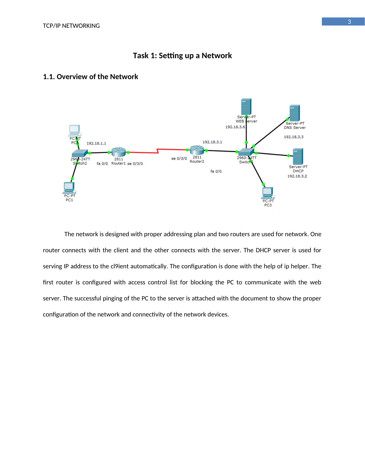
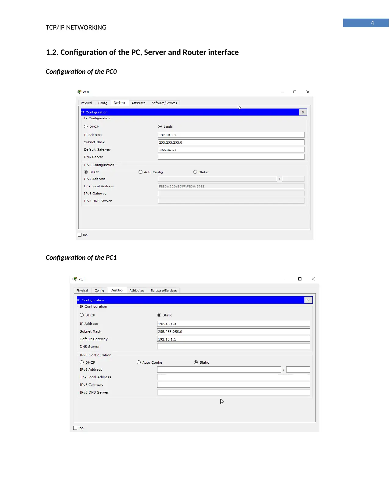
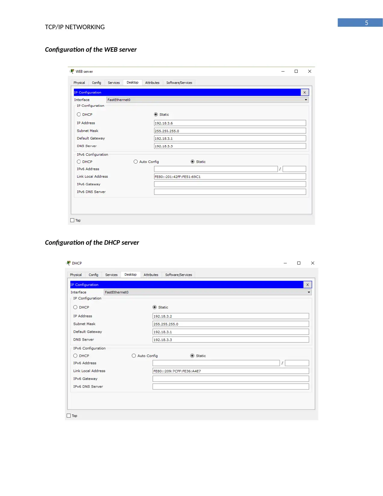
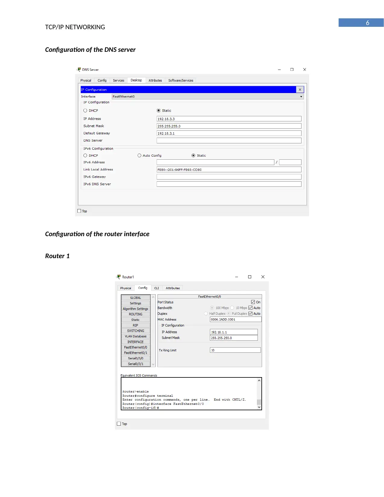
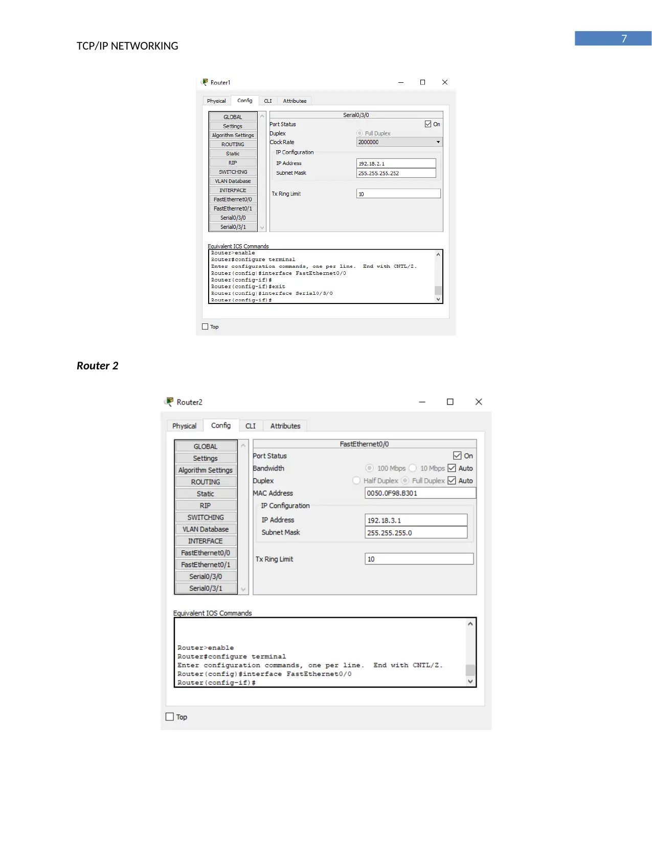
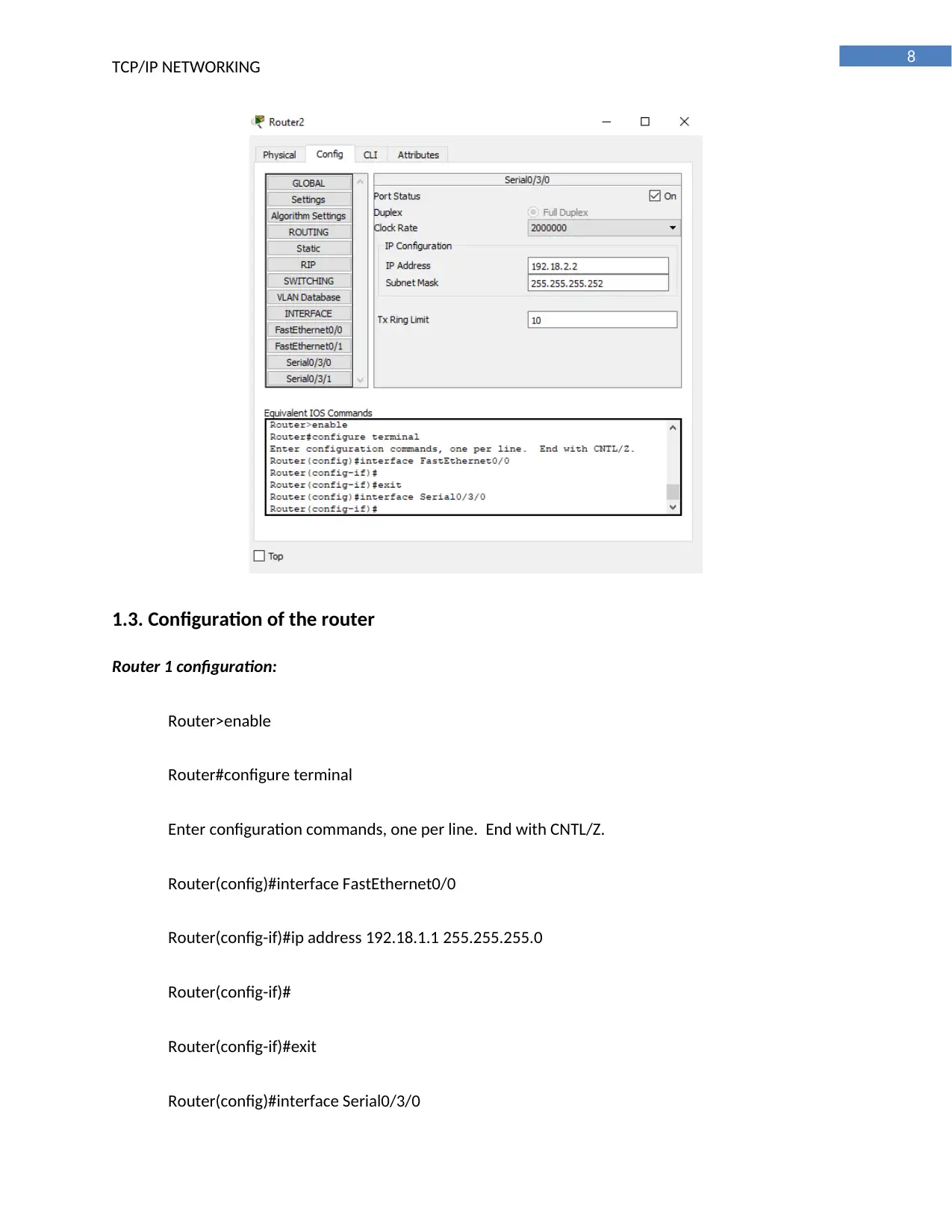
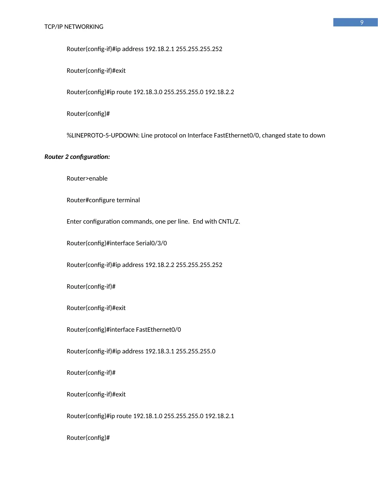
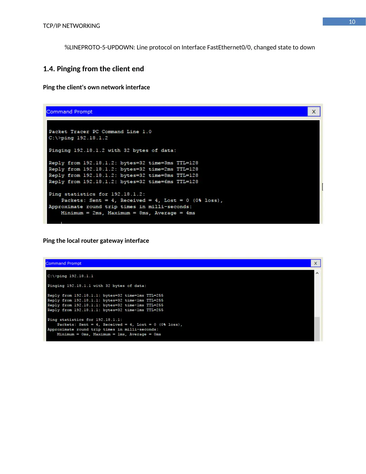
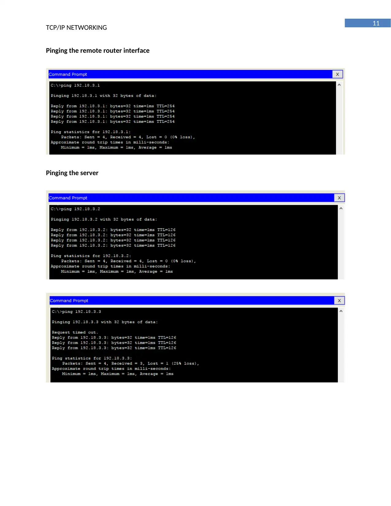
This report outlines the design and implementation of a TCP/IP network using two routers, client PCs, and three servers: DHCP, web, and DNS. The network utilizes a structured addressing scheme with the DHCP server automatically assigning IP addresses to clients connected to the first router. The DNS server provides IP address and hostname resolution. The web server, configured with HTTP, serves web pages to clients. A firewall is implemented to restrict access to the web server from one client PC. The report includes detailed configurations of routers, PCs, and servers, alongside screenshots demonstrating network connectivity and service functionality, such as ping tests and traceroute commands. The document also covers the configuration of DHCP, web server, DNS, and firewall. The report concludes with a bibliography of relevant sources.
Document Page
Running head: TCP/IP NETWORKING
TCP/IP Networking
Name of the Student
Name of the University
Author’s note
tabler-icon-diamond-filled.svg

Paraphrase This Document

Need a fresh take? Get an instant paraphrase of this document with our AI Paraphraser
Document Page
1
TCP/IP NETWORKING
Executive Summary
The report is set up for planning and arranging a system utilizing different system interface that are
associated with installation of routers. Two routers are utilized for outlining the system and the client Pc
are associated with the interface of the primary router and the servers are associated with the interface
of the second router. Three servers are introduced in the system, for example, the DHCP, Web server
and the DNS server. The DHCP server is utilized for designation of IP deliver to the client machine
associated with the interface on the principal router and the DNS server contains the IP address and the
host name of the system and utilized for correspondence with the customer. The web server is arranged
with HTTP for serving the customer clients with the site pages and react to their demand. A firewall is
arranged in the system to square one of the customer PC to get to the WEB server and the screenshots
are joined in the report for demonstration of the configuration of the routers, PC and the servers
connected in the router.
Document Page
2
TCP/IP NETWORKING
Table of Contents
Task 1: Setting up a Network..........................................................................................................3
1.1. Overview of the Network....................................................................................................3
1.2. Configuration of the PC, Server and Router interface.........................................................4
1.3. Configuration of the router.................................................................................................8
1.4. Pinging from the client end...............................................................................................10
1.5. Traceroute command from the client to the server..........................................................12
Task 2- Configuration of the network service...............................................................................13
2.1. DHCP..................................................................................................................................13
2.2. WEB Server........................................................................................................................14
2.3. DNS....................................................................................................................................15
2.4. Firewall..............................................................................................................................16
Bibliography..................................................................................................................................18
Document Page
3
TCP/IP NETWORKING
Task 1: Setting up a Network
1.1. Overview of the Network
The network is designed with proper addressing plan and two routers are used for network. One
router connects with the client and the other connects with the server. The DHCP server is used for
serving IP address to the cl9ient automatically. The configuration is done with the help of ip helper. The
first router is configured with access control list for blocking the PC to communicate with the web
server. The successful pinging of the PC to the server is attached with the document to show the proper
configuration of the network and connectivity of the network devices.
tabler-icon-diamond-filled.svg

Paraphrase This Document

Need a fresh take? Get an instant paraphrase of this document with our AI Paraphraser
Document Page
4
TCP/IP NETWORKING
1.2. Configuration of the PC, Server and Router interface
Configuration of the PC0
Configuration of the PC1
Document Page
5
TCP/IP NETWORKING
Configuration of the WEB server
Configuration of the DHCP server
Document Page
6
TCP/IP NETWORKING
Configuration of the DNS server
Configuration of the router interface
Router 1
tabler-icon-diamond-filled.svg

Paraphrase This Document

Need a fresh take? Get an instant paraphrase of this document with our AI Paraphraser
Document Page
7
TCP/IP NETWORKING
Router 2
Document Page
8
TCP/IP NETWORKING
1.3. Configuration of the router
Router 1 configuration:
Router>enable
Router#configure terminal
Enter configuration commands, one per line. End with CNTL/Z.
Router(config)#interface FastEthernet0/0
Router(config-if)#ip address 192.18.1.1 255.255.255.0
Router(config-if)#
Router(config-if)#exit
Router(config)#interface Serial0/3/0
Document Page
9
TCP/IP NETWORKING
Router(config-if)#ip address 192.18.2.1 255.255.255.252
Router(config-if)#exit
Router(config)#ip route 192.18.3.0 255.255.255.0 192.18.2.2
Router(config)#
%LINEPROTO-5-UPDOWN: Line protocol on Interface FastEthernet0/0, changed state to down
Router 2 configuration:
Router>enable
Router#configure terminal
Enter configuration commands, one per line. End with CNTL/Z.
Router(config)#interface Serial0/3/0
Router(config-if)#ip address 192.18.2.2 255.255.255.252
Router(config-if)#
Router(config-if)#exit
Router(config)#interface FastEthernet0/0
Router(config-if)#ip address 192.18.3.1 255.255.255.0
Router(config-if)#
Router(config-if)#exit
Router(config)#ip route 192.18.1.0 255.255.255.0 192.18.2.1
Router(config)#
tabler-icon-diamond-filled.svg

Paraphrase This Document

Need a fresh take? Get an instant paraphrase of this document with our AI Paraphraser
Document Page
10
TCP/IP NETWORKING
%LINEPROTO-5-UPDOWN: Line protocol on Interface FastEthernet0/0, changed state to down
1.4. Pinging from the client end
Ping the client's own network interface
Ping the local router gateway interface
Document Page
11
TCP/IP NETWORKING
Pinging the remote router interface
Pinging the server
chevron_up_icon
1 out of 20
circle_padding
hide_on_mobile
zoom_out_icon
[object Object]