TCP/IP Network Setup Project: Configuring Devices and Network Services

Verified

Added on  2020/04/07

|36
|1169
|159
Project
AI Summary
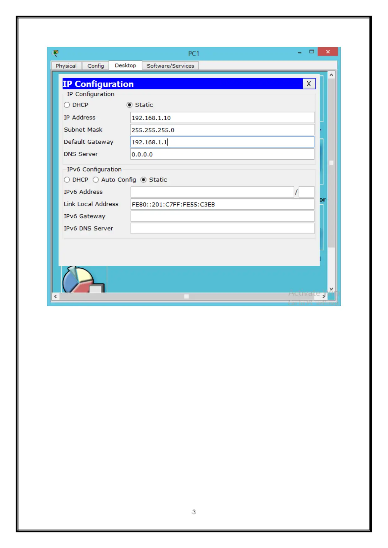
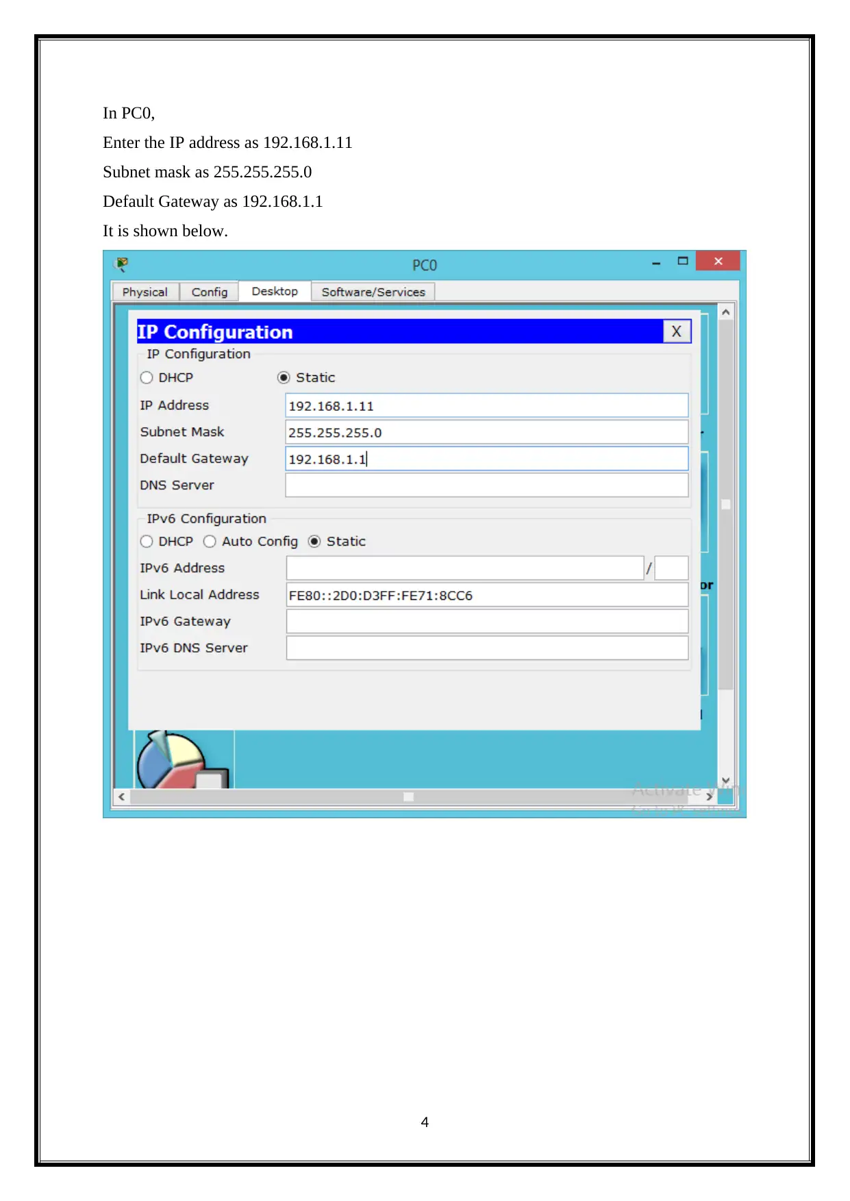
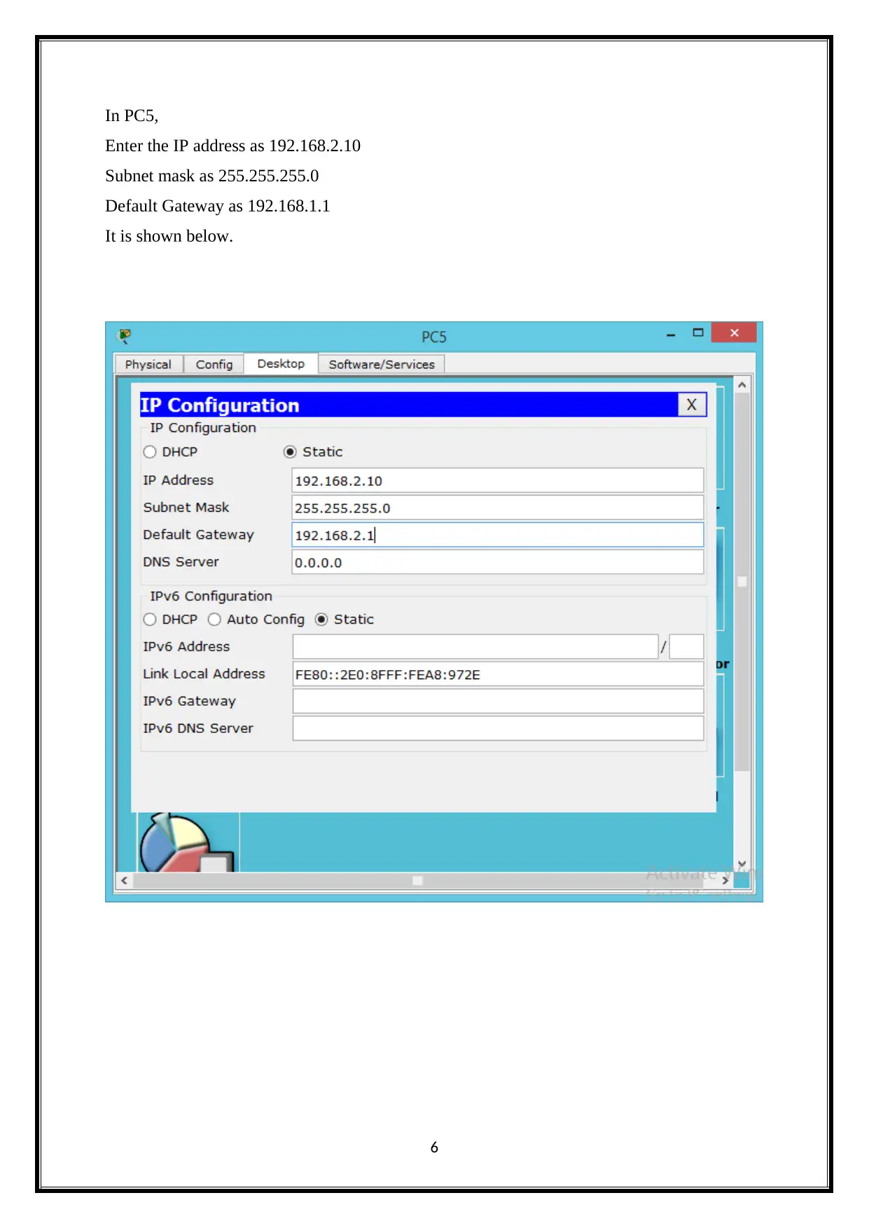
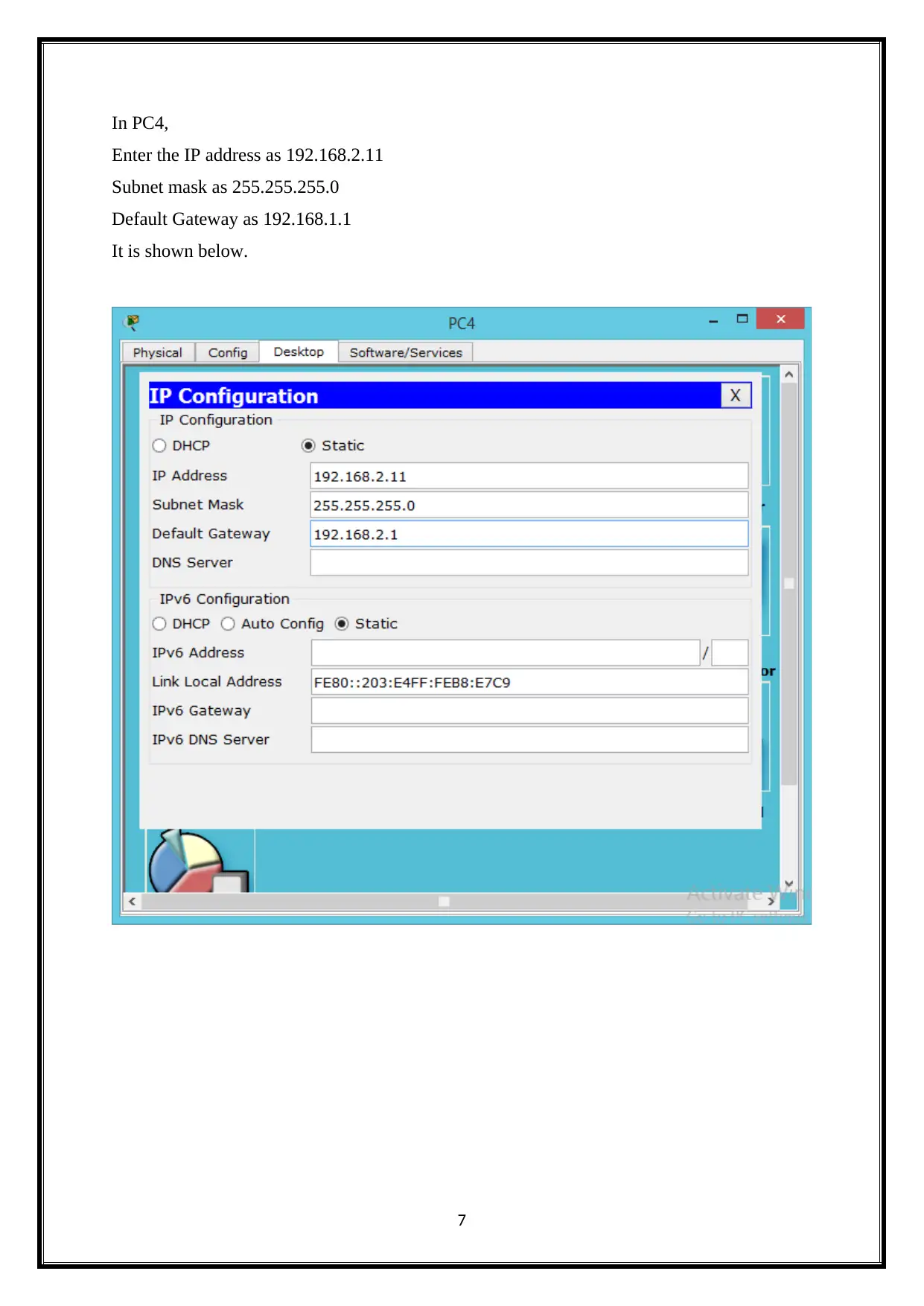
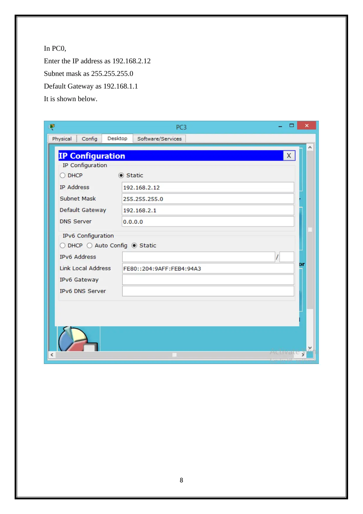
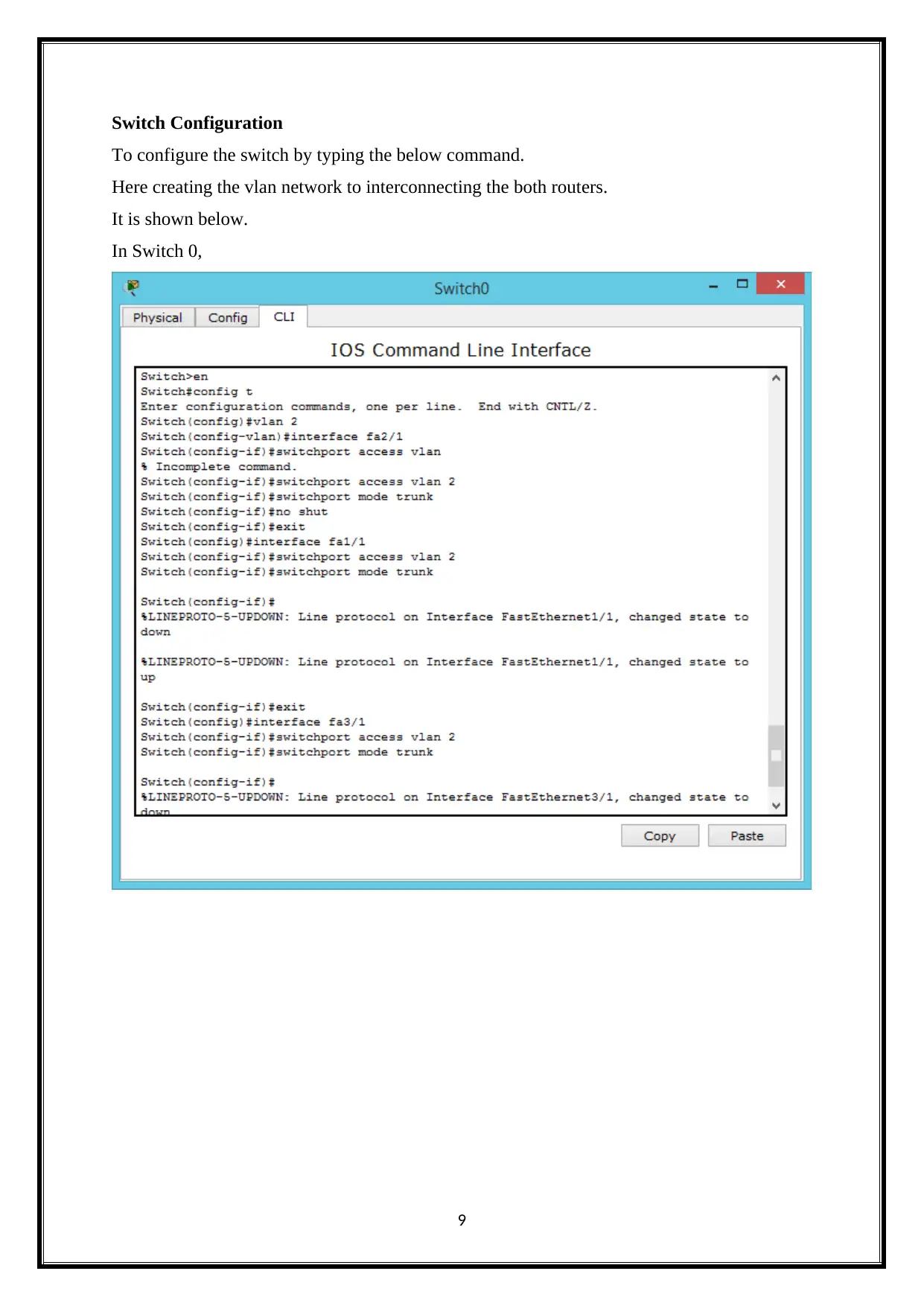
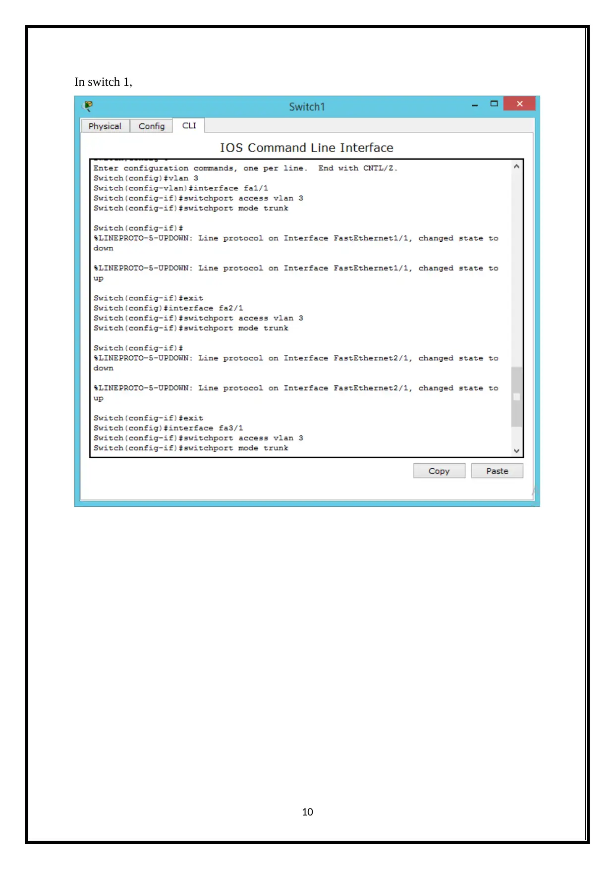
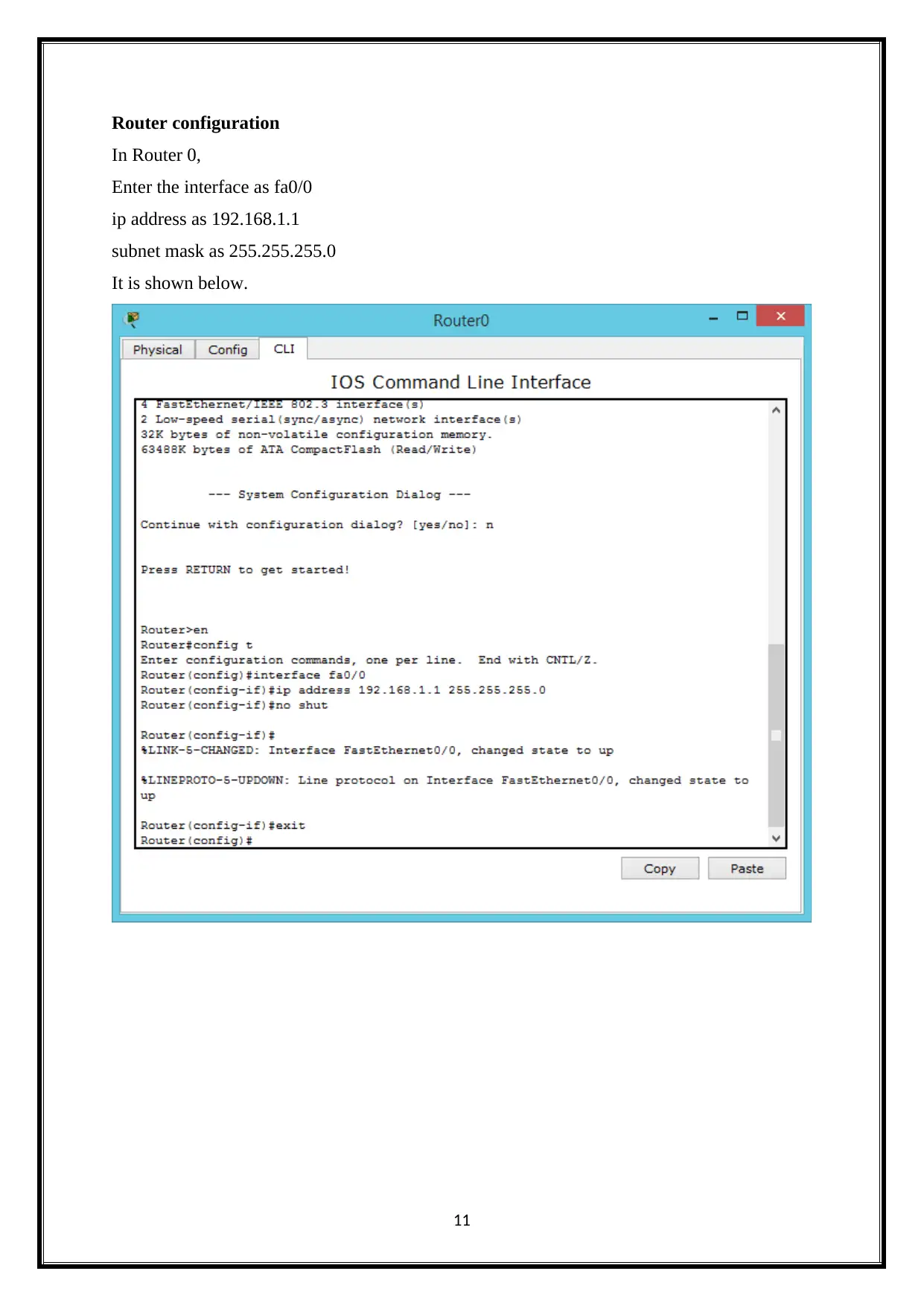
This project report details the creation of a simple network setup using Cisco Packet Tracer. The network consists of two routers, six PCs, and a server, all interconnected and configured for communication. The first task focuses on device configuration, including IP address assignments for each PC, switch configuration, and router setup, including interface configuration and IP routing. The second task covers network service configuration, including DHCP for automatic IP assignment, web browser service setup, DNS server configuration for domain name resolution, and firewall configuration for network security. The project demonstrates the successful implementation and analysis of these network components and services, providing a practical understanding of TCP/IP networking principles. The document also includes ping and traceroute commands to test network connectivity and troubleshoot potential issues. The project provides a comprehensive overview of network design and service configuration in a simulated environment. This assignment, along with others, is available on Desklib for students to enhance their understanding of networking concepts.
Document Page
tcp/ip networking
tabler-icon-diamond-filled.svg

Paraphrase This Document

Need a fresh take? Get an instant paraphrase of this document with our AI Paraphraser
Document Page
Table of Contents
Task – 1 Network Setup.............................................................................................................2
Device Configuration.............................................................................................................2
IP routing configuration.......................................................................................................13
Ping.......................................................................................................................................14
Trace Route command..........................................................................................................17
Task – 2 Network service Configuration.................................................................................19
DHCP...................................................................................................................................19
Web Browser........................................................................................................................26
DNS......................................................................................................................................27
Firewall.................................................................................................................................32
Conclusion................................................................................................................................32
References................................................................................................................................32
1
Document Page
Project Scope
Main objective of the project is to create the simple network setup and it created by
using the cisco network simulator that is cisco packet tracer. It configured each network
devices. The network setup using the two routers, six PC and one server. These are connected
with each other. The network services will be configured and analysed in detail.
Task – 1 Network Setup
Device Configuration
PC configuration
In PC1,
To configure the IP for the PC by using below steps.
Click the PC and select the Desktop
After click the IP configuration.
Then enter the IP address as 192.168.1.10
Subnet mask as 255.255.255.0
Default Gateway as 192.168.1.1
It is shown below (NETworking, 2013).
2
Document Page
3
tabler-icon-diamond-filled.svg

Paraphrase This Document

Need a fresh take? Get an instant paraphrase of this document with our AI Paraphraser
Document Page
In PC0,
Enter the IP address as 192.168.1.11
Subnet mask as 255.255.255.0
Default Gateway as 192.168.1.1
It is shown below.
4
Document Page
In PC2,
Enter the IP address as 192.168.1.12
Subnet mask as 255.255.255.0
Default Gateway as 192.168.1.1
It is shown below.
5
Document Page
In PC5,
Enter the IP address as 192.168.2.10
Subnet mask as 255.255.255.0
Default Gateway as 192.168.1.1
It is shown below.
6
tabler-icon-diamond-filled.svg

Paraphrase This Document

Need a fresh take? Get an instant paraphrase of this document with our AI Paraphraser
Document Page
In PC4,
Enter the IP address as 192.168.2.11
Subnet mask as 255.255.255.0
Default Gateway as 192.168.1.1
It is shown below.
7
Document Page
In PC0,
Enter the IP address as 192.168.2.12
Subnet mask as 255.255.255.0
Default Gateway as 192.168.1.1
It is shown below.
8
Document Page
Switch Configuration
To configure the switch by typing the below command.
Here creating the vlan network to interconnecting the both routers.
It is shown below.
In Switch 0,
9
tabler-icon-diamond-filled.svg

Paraphrase This Document

Need a fresh take? Get an instant paraphrase of this document with our AI Paraphraser
Document Page
In switch 1,
10
Document Page
Router configuration
In Router 0,
Enter the interface as fa0/0
ip address as 192.168.1.1
subnet mask as 255.255.255.0
It is shown below.
11
chevron_up_icon
1 out of 36
circle_padding
hide_on_mobile
zoom_out_icon
[object Object]