TCP/IP Networking Testing and Implementation for NepTech's LAN
VerifiedAdded on 2019/10/30
|18
|2551
|57
Report
AI Summary
This report details the design, implementation, and testing of a TCP/IP network for NepTech, a company with three buildings in Australia. The report covers the selection of IT infrastructure components, including switches, routers, cables, and servers. It explains the configuration of routers, including IP address assignment and interface setup, and demonstrates ping and traceroute tests to verify network connectivity. Furthermore, the report describes the configuration of network services such as DHCP, DNS, and a web server, providing step-by-step instructions and screenshots. The report also includes firewall configuration using access control lists (ACLs) to enhance network security. The document illustrates the practical application of networking concepts and offers recommendations for network management and scalability, making it a valuable resource for students studying networking and related fields.
TCP/IP Networking
Testing on the knowledge on Networking and that is the technical part
and the use of diagrams how this can be applied in real application in
life.
Testing on the knowledge on Networking and that is the technical part
and the use of diagrams how this can be applied in real application in
life.
Paraphrase This Document
Need a fresh take? Get an instant paraphrase of this document with our AI Paraphraser
patel Srinivas reddy
Table of Contents
Executive Summary................................................................................................................................2
Components of IT Infrastructure............................................................................................................3
Components for computer hardware.................................................................................................3
Setting Up the Network..........................................................................................................................4
Configuring The Routers.....................................................................................................................4
Configuring router0........................................................................................................................4
Configuring router1........................................................................................................................6
Pinging................................................................................................................................................7
Traceroute..........................................................................................................................................9
Configuring of Network services..........................................................................................................10
DHCP Configuration..........................................................................................................................10
DNS and WEB SERVER CONFIGURATION..........................................................................................12
References............................................................................................................................................16
1 | P a g e
patel Srinivas reddy
Executive Summary
Network in every organization is a very crucial and a very fundamental basic that requires thorough
understanding when being set up, this is because if a network design is not clear or as per the
requirements this may mess the working of the whole organisation. Many organizations are
upgrading to digital ways nowadays and avoiding paper work. Network has made communication in
these organizations to be easy as the centralized storage and connection especially in case where
LAN and WAN has been set, hence sharing of information over the network.
A good network is described by the way is being set that is the topology applied, the IT
infrastructures components used, the budget or cost of setting the network, the expandability or
extensibility in case need in future and the compatibility with the existing devices in the organization.
In this case scenario we will consider a LAN (Local Area Network) for an organization named NepTech
that is set between Its three storey buildings in Australia. The basic idea is to set the topology by
showing all the configuration from the setting the layout that is the topology to setting up the
simulated network design to physical network design. This will detail in show the configuration of the
computers, the servers, switches, routers and their interfaces clearly showing the network addresses
assigned to each and every component within the network. Also after installing the network then we
need to configure the network services in terms of the DHCP, WEB Server, DNS and the Firewall.
2 | P a g e
⊘ This is a preview!⊘
Do you want full access?
Subscribe today to unlock all pages.
Trusted by 1+ million students worldwide
patel Srinivas reddy
Components of IT Infrastructure
Many different organizations require different various components of IT infrastructure while setting
up and configuring their network in the design that is best according to their requirements. The
following are some of the components of IT infrastructure to be applied in the setting up the network
as per the requirement given.
Components for computer hardware
This are the basic infrastructures in all foundation of a network design. They include:
Switch.
A switch is a gadget used for connecting other computer devices to a LAN(Local Area Network)
(Mitchell, 2017).
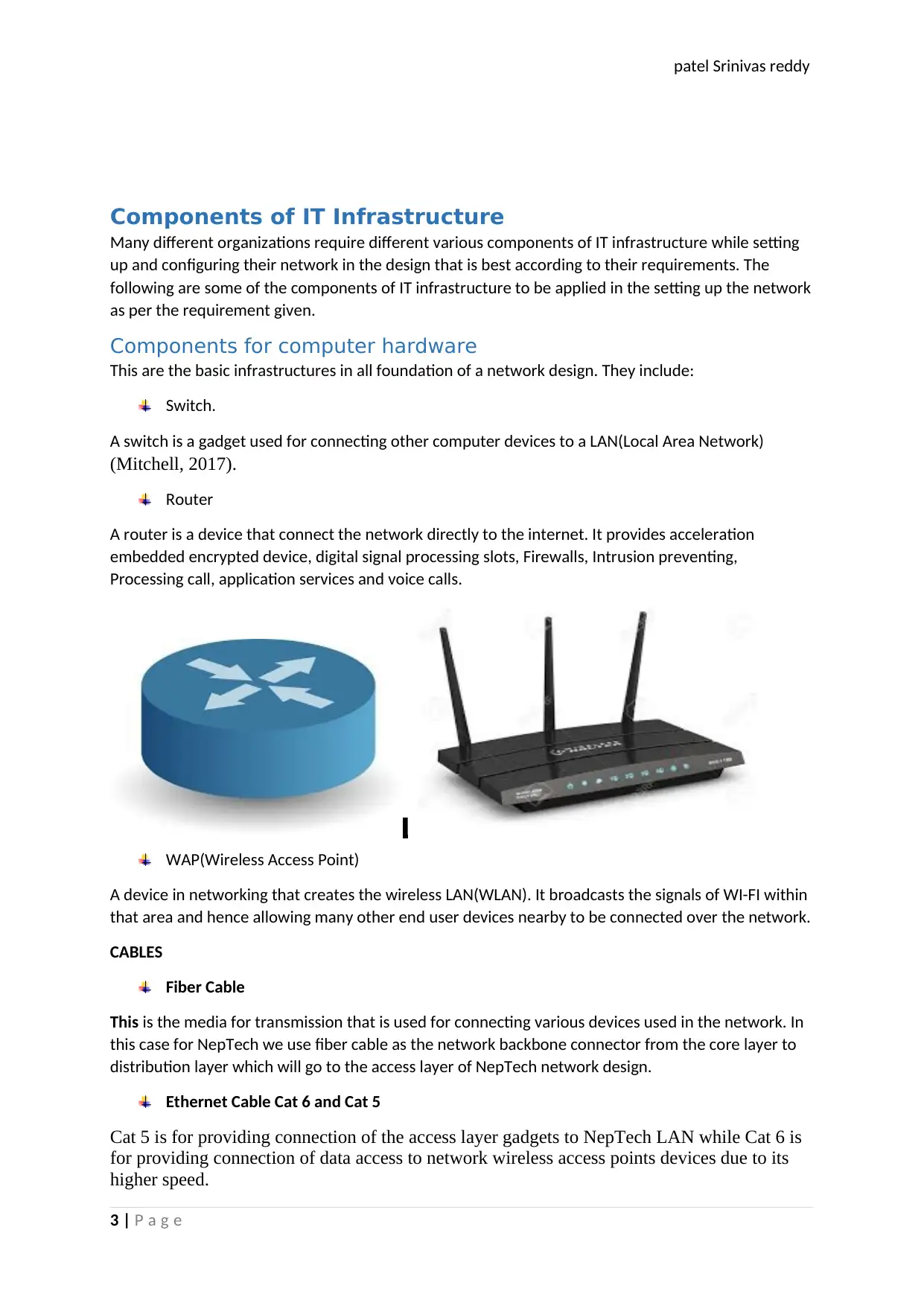
Router
A router is a device that connect the network directly to the internet. It provides acceleration
embedded encrypted device, digital signal processing slots, Firewalls, Intrusion preventing,
Processing call, application services and voice calls.
WAP(Wireless Access Point)
A device in networking that creates the wireless LAN(WLAN). It broadcasts the signals of WI-FI within
that area and hence allowing many other end user devices nearby to be connected over the network.
CABLES
Fiber Cable
This is the media for transmission that is used for connecting various devices used in the network. In
this case for NepTech we use fiber cable as the network backbone connector from the core layer to
distribution layer which will go to the access layer of NepTech network design.
Ethernet Cable Cat 6 and Cat 5
Cat 5 is for providing connection of the access layer gadgets to NepTech LAN while Cat 6 is
for providing connection of data access to network wireless access points devices due to its
higher speed.
3 | P a g e
Components of IT Infrastructure
Many different organizations require different various components of IT infrastructure while setting
up and configuring their network in the design that is best according to their requirements. The
following are some of the components of IT infrastructure to be applied in the setting up the network
as per the requirement given.
Components for computer hardware
This are the basic infrastructures in all foundation of a network design. They include:
Switch.
A switch is a gadget used for connecting other computer devices to a LAN(Local Area Network)
(Mitchell, 2017).
Router
A router is a device that connect the network directly to the internet. It provides acceleration
embedded encrypted device, digital signal processing slots, Firewalls, Intrusion preventing,
Processing call, application services and voice calls.
WAP(Wireless Access Point)
A device in networking that creates the wireless LAN(WLAN). It broadcasts the signals of WI-FI within
that area and hence allowing many other end user devices nearby to be connected over the network.
CABLES
Fiber Cable
This is the media for transmission that is used for connecting various devices used in the network. In
this case for NepTech we use fiber cable as the network backbone connector from the core layer to
distribution layer which will go to the access layer of NepTech network design.
Ethernet Cable Cat 6 and Cat 5
Cat 5 is for providing connection of the access layer gadgets to NepTech LAN while Cat 6 is
for providing connection of data access to network wireless access points devices due to its
higher speed.
3 | P a g e
Paraphrase This Document
Need a fresh take? Get an instant paraphrase of this document with our AI Paraphraser
patel Srinivas reddy
Server and Storage Components
Servers are component that manages the access to resources and services shared in the network.
This include the Domain Name Server (DNS), DHCP server, File Server, DB server, Mail server and the
DNS Server.
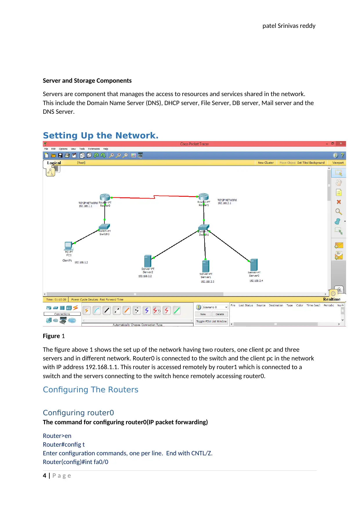
Setting Up the Network.
Figure 1
The figure above 1 shows the set up of the network having two routers, one client pc and three
servers and in different network. Router0 is connected to the switch and the client pc in the network
with IP address 192.168.1.1. This router is accessed remotely by router1 which is connected to a
switch and the servers connecting to the switch hence remotely accessing router0.
Configuring The Routers
Configuring router0
The command for configuring router0(IP packet forwarding)
Router>en
Router#config t
Enter configuration commands, one per line. End with CNTL/Z.
Router(config)#int fa0/0
4 | P a g e
Server and Storage Components
Servers are component that manages the access to resources and services shared in the network.
This include the Domain Name Server (DNS), DHCP server, File Server, DB server, Mail server and the
DNS Server.
Setting Up the Network.
Figure 1
The figure above 1 shows the set up of the network having two routers, one client pc and three
servers and in different network. Router0 is connected to the switch and the client pc in the network
with IP address 192.168.1.1. This router is accessed remotely by router1 which is connected to a
switch and the servers connecting to the switch hence remotely accessing router0.
Configuring The Routers
Configuring router0
The command for configuring router0(IP packet forwarding)
Router>en
Router#config t
Enter configuration commands, one per line. End with CNTL/Z.
Router(config)#int fa0/0
4 | P a g e
patel Srinivas reddy
Router(config-if)#ip address 192.168.1.1 255.255.255.0
Router(config-if)#nondescription router0 1range
Router(config-if)#
Router(config-if)#eiexit
Router(config)#exit
Router#
%SYS-5-CONFIG_I: Configured from console by console
Router#configure terminal
Enter configuration commands, one per line. End with CNTL/Z.
Router(config)#interface FastEthernet0/0
Router(config-if)#no shutdown
Router(config-if)#
%LINK-5-CHANGED: Interface FastEthernet0/0, changed state to up
%LINEPROTO-5-UPDOWN: Line protocol on Interface FastEthernet0/0, changed state to up
Router(config-if)#exit
Router(config)#exit
Router#
%SYS-5-CONFIG_I: Configured from console by console
Router#config t
Enter configuration commands, one per line. End with CNTL/Z.
Router(config)#interface
% Incomplete command.
Router(config)#int se2/0
Router(config-if)#
Router(config-if)#ip address 192.168.2.1 255.255.255.0
Router(config-if)#
Router(config-if)#clock rate 64000
Router(config-if)#
Router(config-if)#no shutdown
%LINK-5-CHANGED: Interface Serial2/0, changed state to down
Router(config-if)#
%LINK-5-CHANGED: Interface Serial2/0, changed state to up
%LINEPROTO-5-UPDOWN: Line protocol on Interface Serial2/0, changed state to up
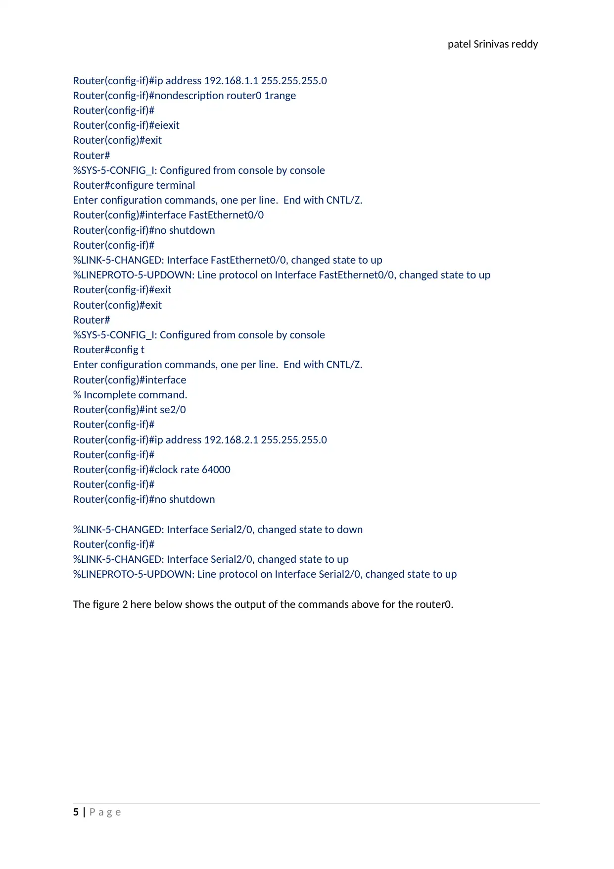
The figure 2 here below shows the output of the commands above for the router0.
5 | P a g e
Router(config-if)#ip address 192.168.1.1 255.255.255.0
Router(config-if)#nondescription router0 1range
Router(config-if)#
Router(config-if)#eiexit
Router(config)#exit
Router#
%SYS-5-CONFIG_I: Configured from console by console
Router#configure terminal
Enter configuration commands, one per line. End with CNTL/Z.
Router(config)#interface FastEthernet0/0
Router(config-if)#no shutdown
Router(config-if)#
%LINK-5-CHANGED: Interface FastEthernet0/0, changed state to up
%LINEPROTO-5-UPDOWN: Line protocol on Interface FastEthernet0/0, changed state to up
Router(config-if)#exit
Router(config)#exit
Router#
%SYS-5-CONFIG_I: Configured from console by console
Router#config t
Enter configuration commands, one per line. End with CNTL/Z.
Router(config)#interface
% Incomplete command.
Router(config)#int se2/0
Router(config-if)#
Router(config-if)#ip address 192.168.2.1 255.255.255.0
Router(config-if)#
Router(config-if)#clock rate 64000
Router(config-if)#
Router(config-if)#no shutdown
%LINK-5-CHANGED: Interface Serial2/0, changed state to down
Router(config-if)#
%LINK-5-CHANGED: Interface Serial2/0, changed state to up
%LINEPROTO-5-UPDOWN: Line protocol on Interface Serial2/0, changed state to up
The figure 2 here below shows the output of the commands above for the router0.
5 | P a g e
⊘ This is a preview!⊘
Do you want full access?
Subscribe today to unlock all pages.
Trusted by 1+ million students worldwide
patel Srinivas reddy
Figure 2 Configuration of router0
After all the commands has been set the route is supposed to be active and on in a manner that it
can now communicate with the device attached to it. It is ip routed with the router1 which is
accessing it remotely over another network and that can be clearly shown on the commands as
above.
Configuring router1
The command for configuring router1(IP packet forwarding)
Router>en
Router#config t
Enter configuration commands, one per line. End with CNTL/Z.
Router(config)#
Router(config)#interface FastEthernet0/0
Router(config-if)#int fa0/0
Router(config-if)#ip address 192.168.2.1 255.255.255.0
Router(config-if)#no shutdown
Router(config-if)#
%LINK-5-CHANGED: Interface FastEthernet0/0, changed state to up
%LINEPROTO-5-UPDOWN: Line protocol on Interface FastEthernet0/0, changed state to up
Router(config-if)#exit
Router(config)#exit
Router#
%SYS-5-CONFIG_I: Configured from console by console
Router#config t
Enter configuration commands, one per line. End with CNTL/Z.
Router(config)#int se2/0
Router(config-if)#
Router(config-if)#ip address 192.168.1.1 255.255.255.0
Router(config-if)#
Router(config-if)#no shutdown
Router(config-if)#
%LINK-5-CHANGED: Interface Serial2/0, changed state to up
%LINEPROTO-5-UPDOWN: Line protocol on Interface Serial2/0, changed state to up
6 | P a g e
Paraphrase This Document
Need a fresh take? Get an instant paraphrase of this document with our AI Paraphraser
patel Srinivas reddy
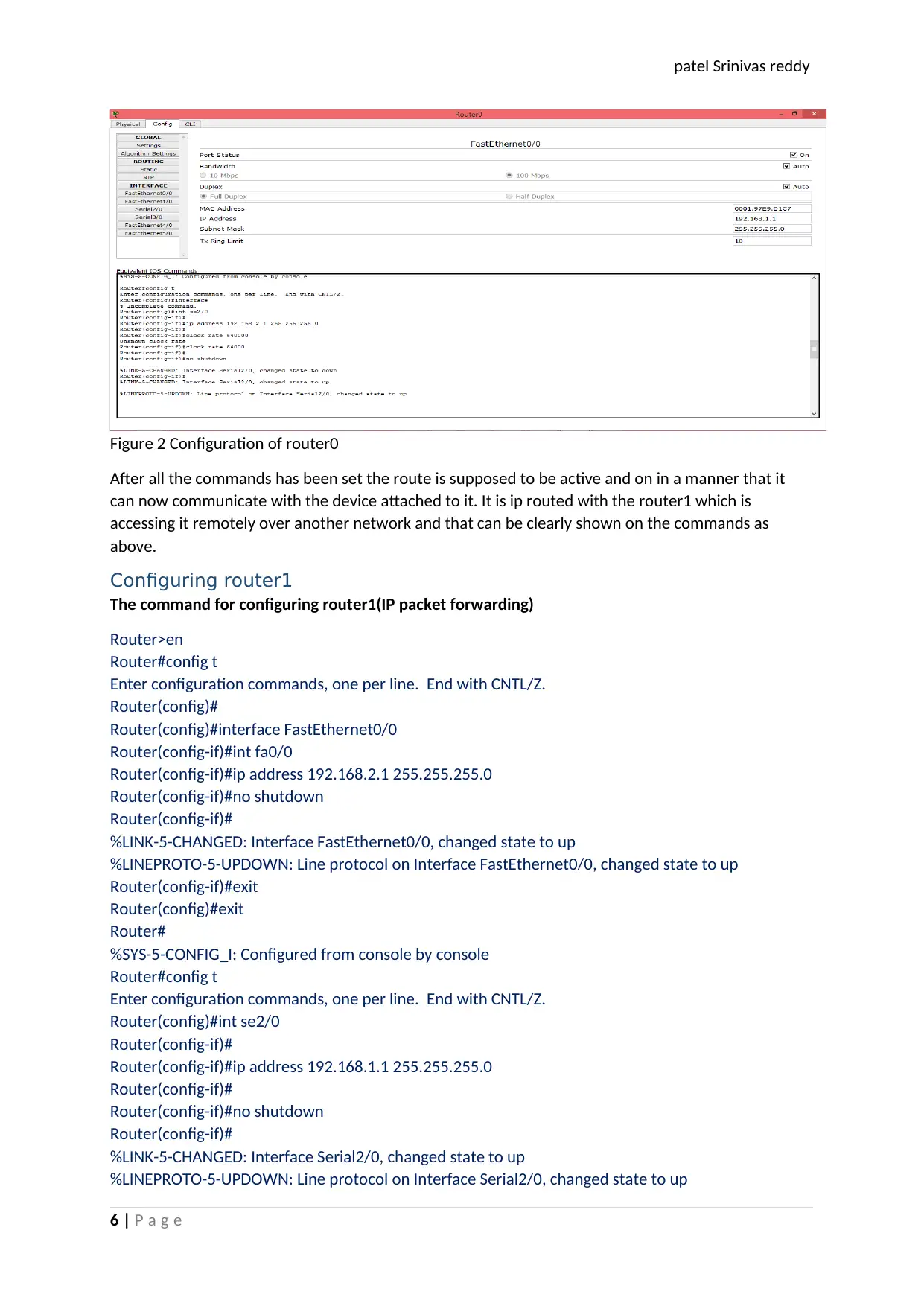
After all the commands has been set the router2 is supposed to be active and signal green now and
not red and in a manner that it can now communicate with the devices attached to it and also with
the gateway router. It is ip routed with the router0 which is on another network with clients or end
user devices and that can be clearly shown as on the commands as above. The figure below shows
the output after the command have been implemented.
Figure 3 Configuration of router1
Pinging
Pinging for Client Pc on the gateway network
7 | P a g e
patel Srinivas reddy
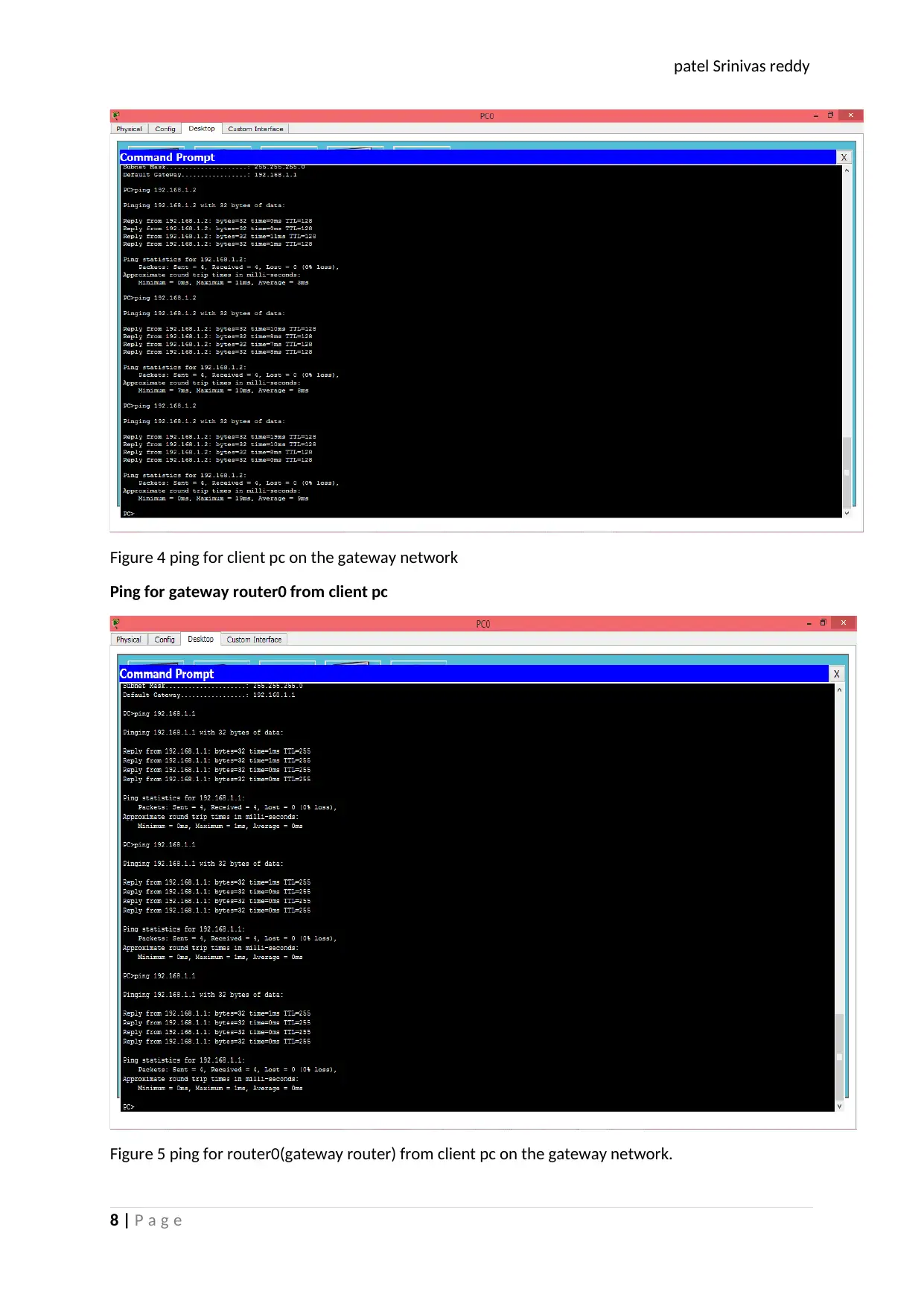
Figure 4 ping for client pc on the gateway network
Ping for gateway router0 from client pc
Figure 5 ping for router0(gateway router) from client pc on the gateway network.
8 | P a g e
Figure 4 ping for client pc on the gateway network
Ping for gateway router0 from client pc
Figure 5 ping for router0(gateway router) from client pc on the gateway network.
8 | P a g e
⊘ This is a preview!⊘
Do you want full access?
Subscribe today to unlock all pages.
Trusted by 1+ million students worldwide
patel Srinivas reddy
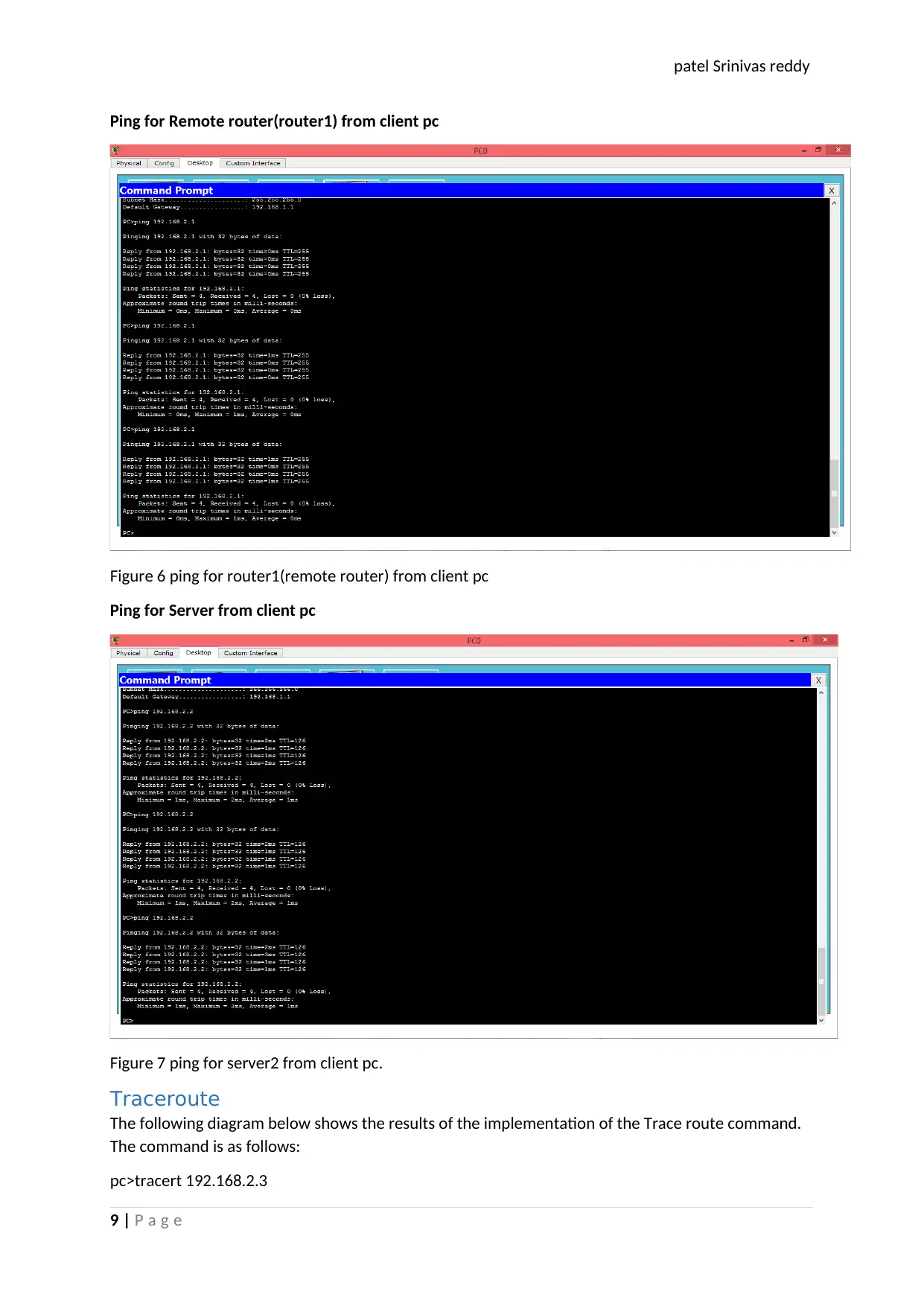
Ping for Remote router(router1) from client pc
Figure 6 ping for router1(remote router) from client pc
Ping for Server from client pc
Figure 7 ping for server2 from client pc.
Traceroute
The following diagram below shows the results of the implementation of the Trace route command.
The command is as follows:
pc>tracert 192.168.2.3
9 | P a g e
Paraphrase This Document
Need a fresh take? Get an instant paraphrase of this document with our AI Paraphraser
patel Srinivas reddy
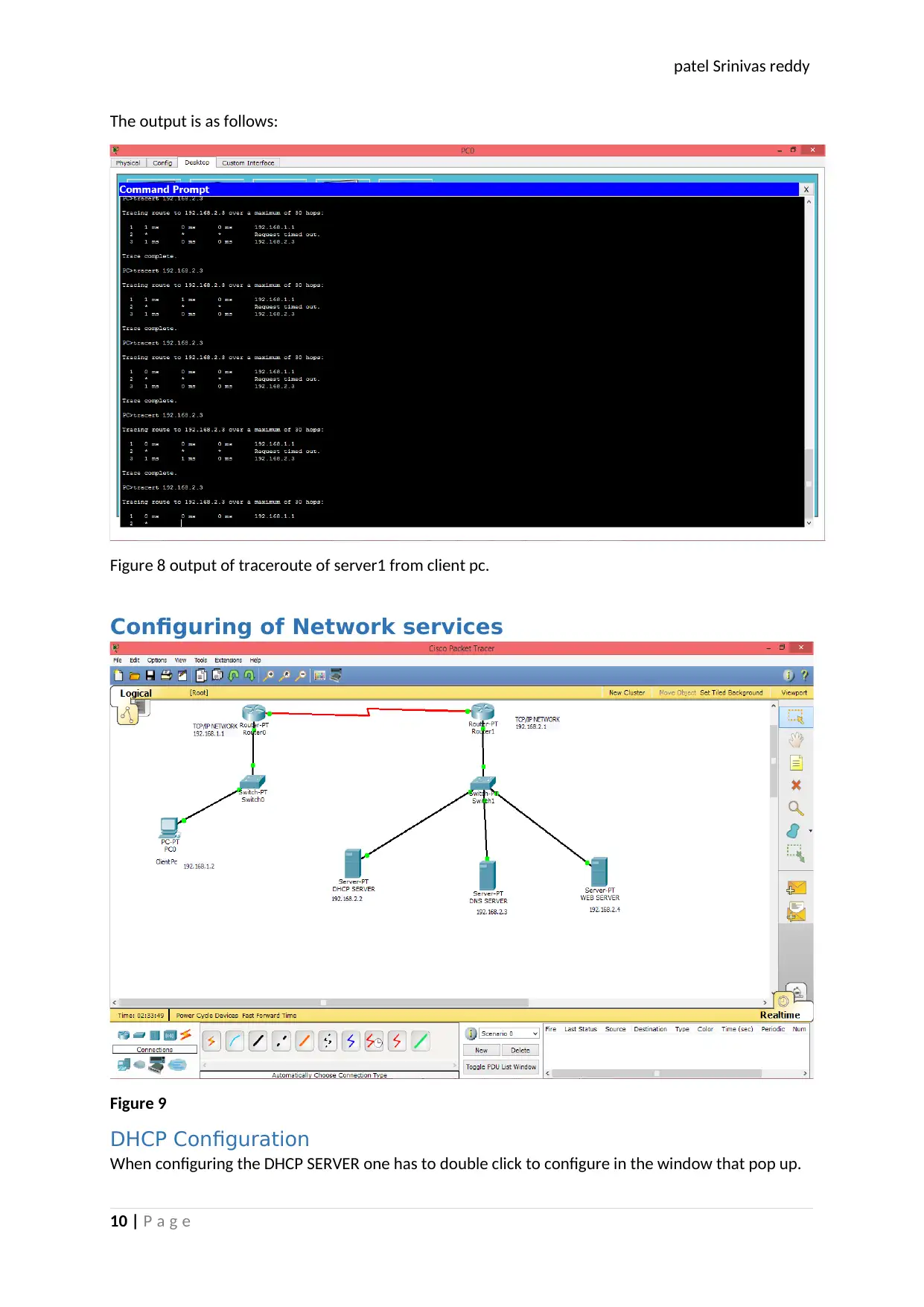
The output is as follows:
Figure 8 output of traceroute of server1 from client pc.
Configuring of Network services
Figure 9
DHCP Configuration
When configuring the DHCP SERVER one has to double click to configure in the window that pop up.
10 | P a g e
The output is as follows:
Figure 8 output of traceroute of server1 from client pc.
Configuring of Network services
Figure 9
DHCP Configuration
When configuring the DHCP SERVER one has to double click to configure in the window that pop up.
10 | P a g e
patel Srinivas reddy
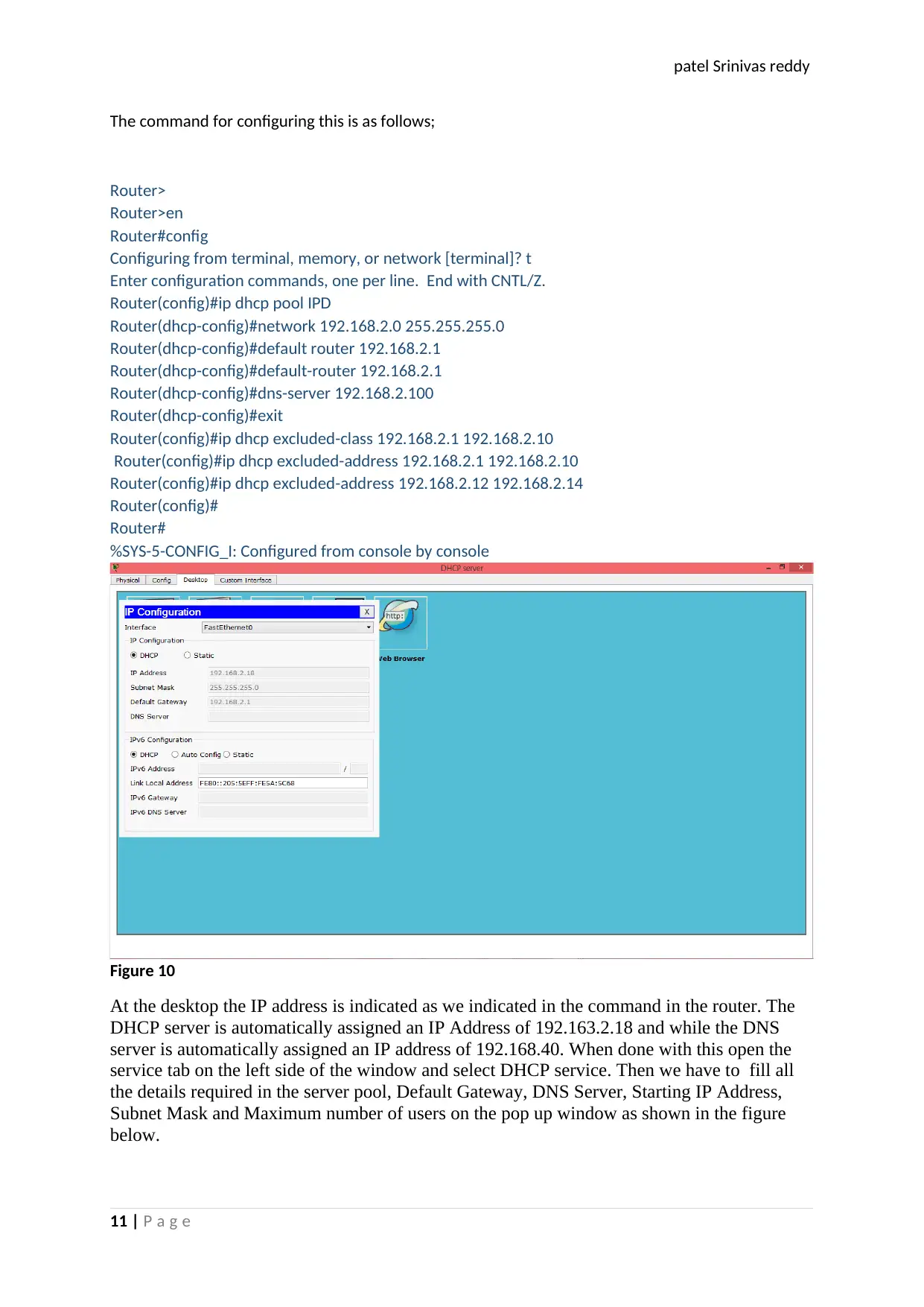
The command for configuring this is as follows;
Router>
Router>en
Router#config
Configuring from terminal, memory, or network [terminal]? t
Enter configuration commands, one per line. End with CNTL/Z.
Router(config)#ip dhcp pool IPD
Router(dhcp-config)#network 192.168.2.0 255.255.255.0
Router(dhcp-config)#default router 192.168.2.1
Router(dhcp-config)#default-router 192.168.2.1
Router(dhcp-config)#dns-server 192.168.2.100
Router(dhcp-config)#exit
Router(config)#ip dhcp excluded-class 192.168.2.1 192.168.2.10
Router(config)#ip dhcp excluded-address 192.168.2.1 192.168.2.10
Router(config)#ip dhcp excluded-address 192.168.2.12 192.168.2.14
Router(config)#
Router#
%SYS-5-CONFIG_I: Configured from console by console
Figure 10
At the desktop the IP address is indicated as we indicated in the command in the router. The
DHCP server is automatically assigned an IP Address of 192.163.2.18 and while the DNS
server is automatically assigned an IP address of 192.168.40. When done with this open the
service tab on the left side of the window and select DHCP service. Then we have to fill all
the details required in the server pool, Default Gateway, DNS Server, Starting IP Address,
Subnet Mask and Maximum number of users on the pop up window as shown in the figure
below.
11 | P a g e
⊘ This is a preview!⊘
Do you want full access?
Subscribe today to unlock all pages.
Trusted by 1+ million students worldwide
1 out of 18
Related Documents


Your All-in-One AI-Powered Toolkit for Academic Success.
+13062052269
info@desklib.com
Available 24*7 on WhatsApp / Email
![[object Object]](/_next/static/media/star-bottom.7253800d.svg)
Unlock your academic potential
Copyright © 2020–2026 A2Z Services. All Rights Reserved. Developed and managed by ZUCOL.