TCP/IP Networks: OSI Model, Subnetting and IP Addressing Solutions
VerifiedAdded on 2023/04/17
|13
|1797
|131
Homework Assignment
AI Summary
This document provides detailed solutions to a TCP/IP networking assignment. It covers the OSI model, explaining each layer's function and differentiating between hardware and software layers. The assignment also includes a hands-on subnetting project using GestioIP calculator and an analysis of IPv6 header fields using Wireshark. Furthermore, it addresses IP addressing concepts and presents a case study involving IP address design for a growing organization, including subnetting calculations and considerations for migrating to IPv6. The solutions provide a comprehensive understanding of key networking concepts and practical applications.

Assessment No
Assessment Title
Student Name & ID
Subject Name and Code
Student Email Address
Assessment Title
Student Name & ID
Subject Name and Code
Student Email Address
Paraphrase This Document
Need a fresh take? Get an instant paraphrase of this document with our AI Paraphraser
TCP/IP
Question 1
OSI Model denotes to a reference model that designates how computing applications
communicate to each other over the network.
This model reference offers a guide role to developers and vendors so as the digital software
programs and communication products they are able to interoperate. Additionally, it facilitates an
open framework which describes the functions of telecommunication and networking systems.
OSI model notion is that the method of communication between end-to-end in a network can be
subdivided into 7 separate sections of related layers/functions. The layers are made in such
manner that each layer serves the layer above it. Below are the OSI layers together with their
summarized functions in a table:
7 - Application Layer This is a network OSI layer where data/application is presented in
a visual manner that a user can decode. Note that this is not an
application by itself, it denotes to services that an application
should have a capacity to make use of it.
6 – Presentation layer Presentation layer is responsible for data display and formatting.
This allows compatibility.
5 – Session layer The session layer is responsible for management of sessions
between end-to-end applications.
4 – Transport layer Transport layer is responsible for transfer of information between
end-to-end devices and deals with errors for instance duplicate and
lost packets.
3 – Network layer Network layer is responsible for information routing via the
network permitting systems to interact.
2 – Data link Layer Also called link layer, it is responsible for transmission of data
across a connection.
1 – Physical layer This layer is responsible for mechanical time and electrical across
a link
OSI model layers can be broadly be grouped into two sections. That is hardware and software
layers. Software layers denotes to the top three layers (i.e. application, session and presentation
layers). These layers are termed as software since they designate how networking programs
within host computers communicate with each other together with the operators (Lammle, 2015).
Hardware OSI application layers on the other hand are the four lower bottom layers. These layers
designate how data is transferred via the physical medium. These layers are transport layer, data
link layer, physical layer and network layer and the medium of transmission include fiber optics,
wire, routers, switches and cables. This hardware layer control the reconstruction of a data
transmission stream from the originating computer to the destination computer.
The TCP/IP or DoD model’s internet model maps OSI’s network model. This because network
model’s responsibility is to ensure that data is packaged, devices are appropriately addressed and
information transmitted. The internet layer was introduced, there existed no internet we are well
versed of today. The internet layer’s function was to define the how data is transmitted between
two computers. This was purposely to allow sharing of information.
Question 2
Hands – On Project 2-3
Subnetting in computer networking is a subject that defines how network is subdivided into
small groups. The subdivision aims at having smaller manageable subnets, more secure subnets
and an ease network to troubleshoot just in case of failure. Normally, the subdivisions are
assigned to organizational departments. That is to say, each department will be in its own subnet.
Note that a mechanism has to be developed to allow intercommunication of the subnets. Subnets
cannot operate in their own exclusions.
Subnetting can be of classful or classless. Classfull subnetting refers to the kind of division in
which each division/subnet/department will have equal subnet mask. This type of subnetting is
the easiest but it is not efficient. That is to say, it wastes a lot of IP addresses which remains
unused. On the other hand, classless subnetting entails having sub-networks whose subnet masks
⊘ This is a preview!⊘
Do you want full access?
Subscribe today to unlock all pages.
Trusted by 1+ million students worldwide
are of different sizes. This recommended subnetting type since it does not allow wastage of IP
addresses (Velte & Velte, 2013).
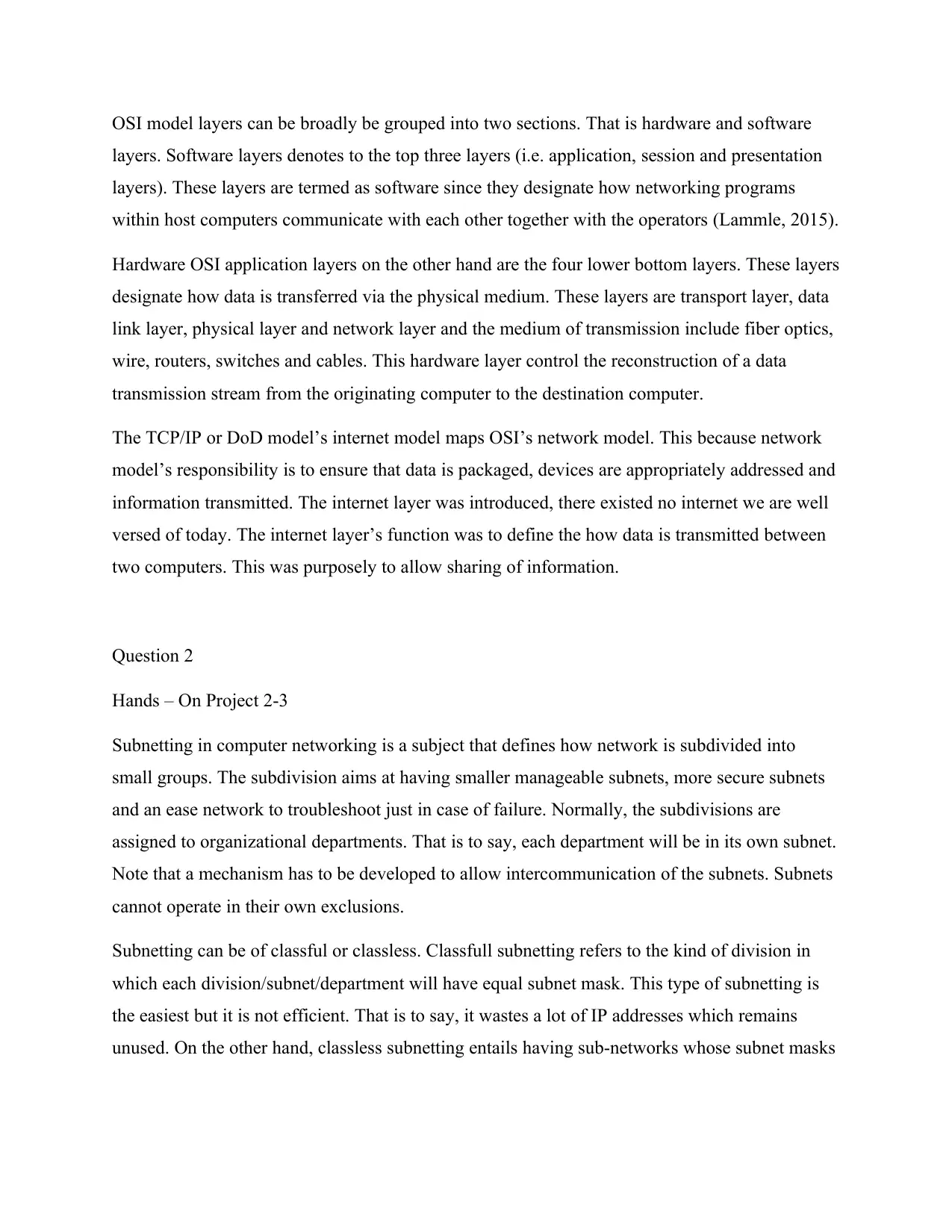
The subnetting task can be achieved by either carrying it out manual or by use of a network
subnetting tool. In this task, having provided with an IP address of 192.168.0.0, and asked to use
GestioIP calculator to calculate 24 subnets, below are activities to achieve the goal:
a. Launch a browser, copy paste the link below and paste into browser’s URL area.
Below window is displayed.
b. Make sure that IPv4 button is active. If not, click on it to activate it. This is because we
are working with an IPv4 address.
c. In the IP address area, enter 192.168.0.0, this our provided IP address.
d. Click on the BM drop-down arrow in the menu. Scroll down to select 24 (255.255.255.0).
Click on the calculate link to obtained the desired results.
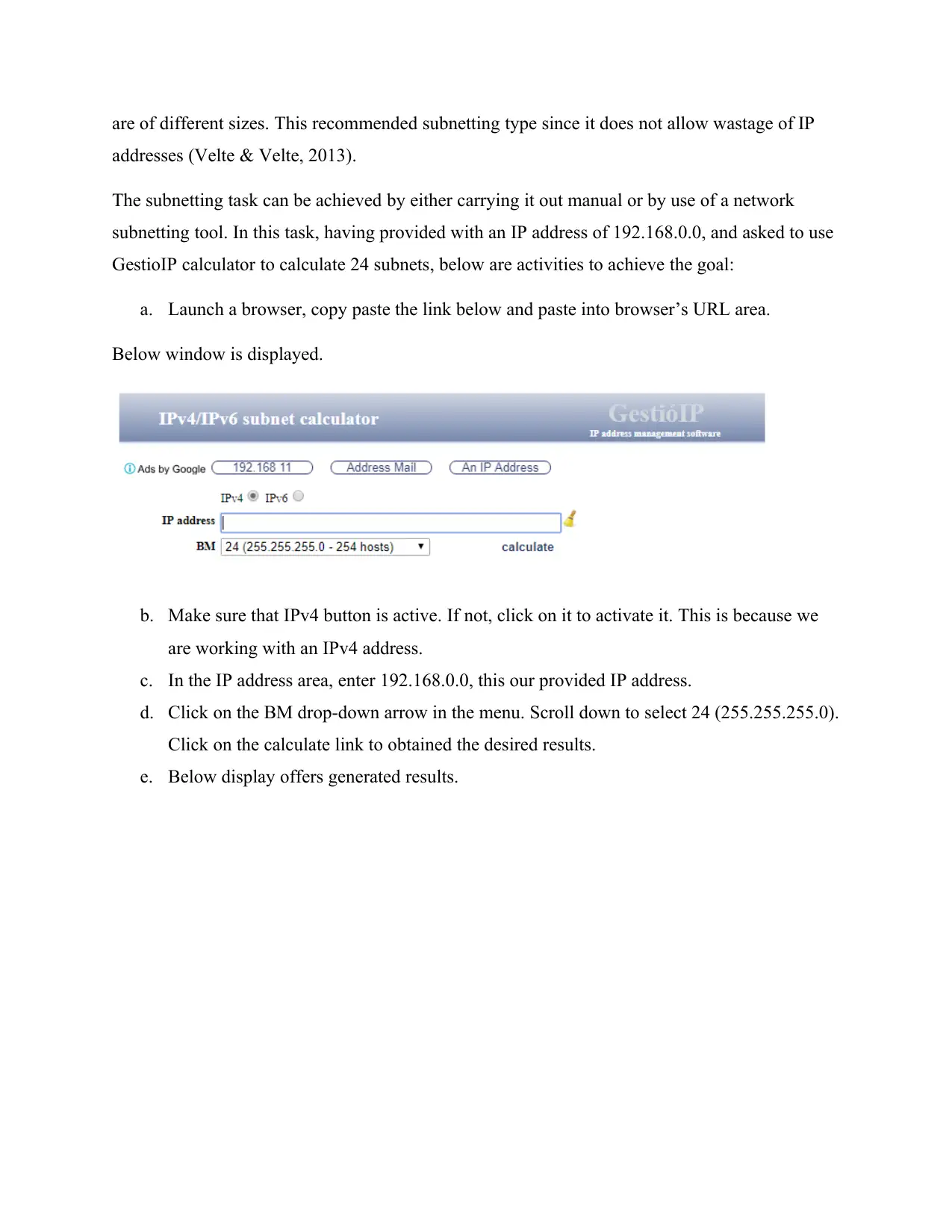
e. Below display offers generated results.
addresses (Velte & Velte, 2013).
The subnetting task can be achieved by either carrying it out manual or by use of a network
subnetting tool. In this task, having provided with an IP address of 192.168.0.0, and asked to use
GestioIP calculator to calculate 24 subnets, below are activities to achieve the goal:
a. Launch a browser, copy paste the link below and paste into browser’s URL area.
Below window is displayed.
b. Make sure that IPv4 button is active. If not, click on it to activate it. This is because we
are working with an IPv4 address.
c. In the IP address area, enter 192.168.0.0, this our provided IP address.
d. Click on the BM drop-down arrow in the menu. Scroll down to select 24 (255.255.255.0).
Click on the calculate link to obtained the desired results.
e. Below display offers generated results.
Paraphrase This Document
Need a fresh take? Get an instant paraphrase of this document with our AI Paraphraser
(Uebel, 2019)
Hands – On Project 3.2
For this task, we will be using a Wireshark file name ch03_IPv6Fields.pcapng downloaded from
student companion site (Cengage, 2019).
Below steps are taken to work on the hands-on project:
a. Launch Wireshark application.
Hands – On Project 3.2
For this task, we will be using a Wireshark file name ch03_IPv6Fields.pcapng downloaded from
student companion site (Cengage, 2019).
Below steps are taken to work on the hands-on project:
a. Launch Wireshark application.
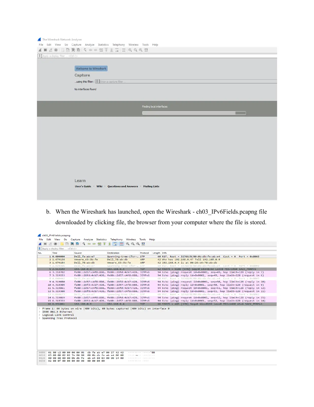
b. When the Wireshark has launched, open the Wireshark - ch03_IPv6Fields.pcapng file
downloaded by clicking file, the browser from your computer where the file is stored.
downloaded by clicking file, the browser from your computer where the file is stored.
⊘ This is a preview!⊘
Do you want full access?
Subscribe today to unlock all pages.
Trusted by 1+ million students worldwide
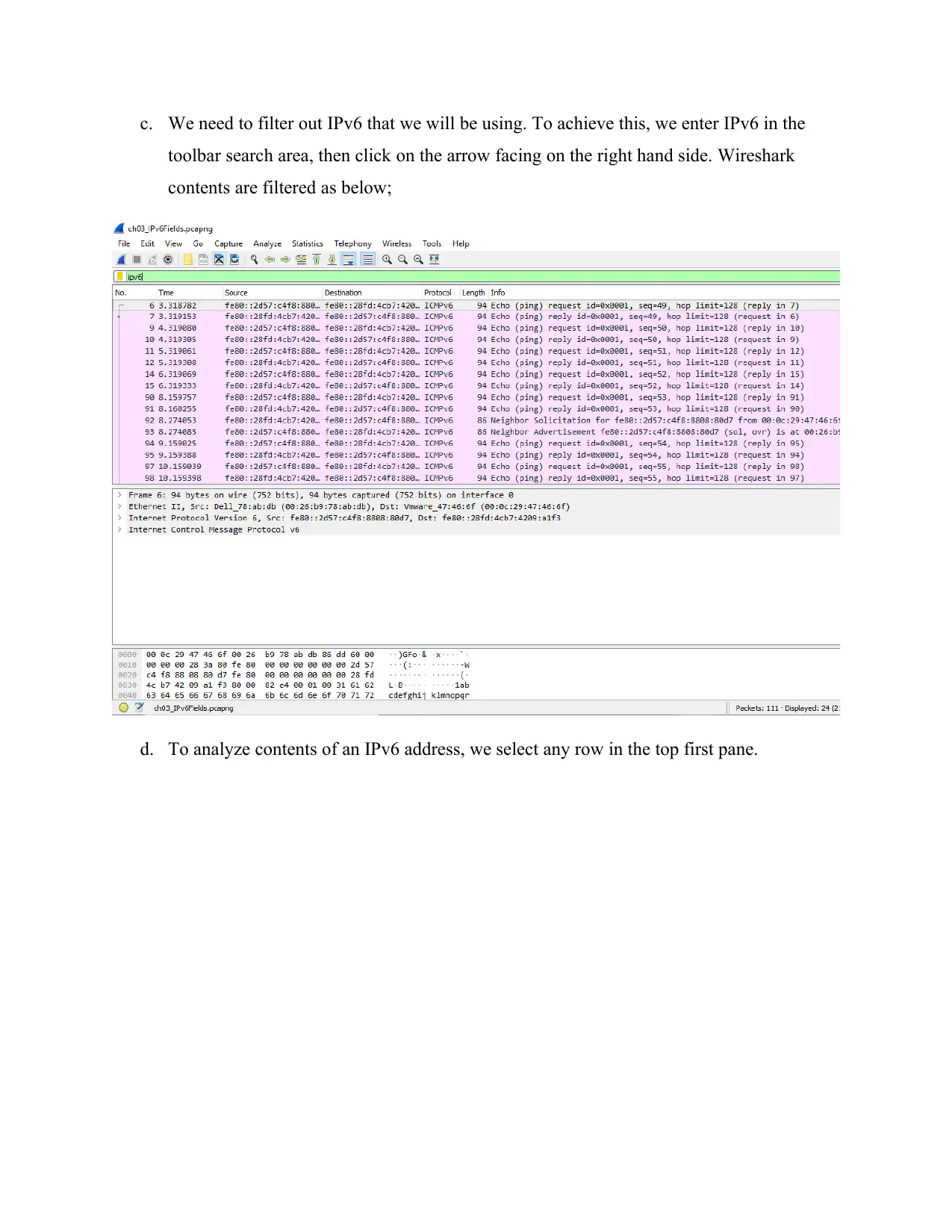
c. We need to filter out IPv6 that we will be using. To achieve this, we enter IPv6 in the
toolbar search area, then click on the arrow facing on the right hand side. Wireshark
contents are filtered as below;
d. To analyze contents of an IPv6 address, we select any row in the top first pane.
toolbar search area, then click on the arrow facing on the right hand side. Wireshark
contents are filtered as below;
d. To analyze contents of an IPv6 address, we select any row in the top first pane.
Paraphrase This Document
Need a fresh take? Get an instant paraphrase of this document with our AI Paraphraser
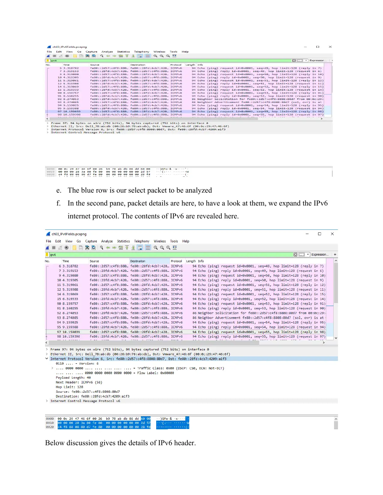
e. The blue row is our select packet to be analyzed
f. In the second pane, packet details are here, to have a look at them, we expand the IPv6
internet protocol. The contents of IPv6 are revealed here.
Below discussion gives the details of IPv6 header.
f. In the second pane, packet details are here, to have a look at them, we expand the IPv6
internet protocol. The contents of IPv6 are revealed here.
Below discussion gives the details of IPv6 header.
i. Payload length
The payload length area field present in the IPv6 header refers to the length of the IPv6 payload.
Two bytes is the size of this field. The payload length field includes layer PDU and headers for
the IPv6 extensions. IPv6 packet has a maximum of 65535 bytes. In case an IPv6 packet is in
excess of 65535, payload field is flagged as zero and jumbo.
ii. Next header
Next header field area explains the protocols in PDU top layer (that is, ICMPv6, TCP and/or
UDP). Observing our header, the next header is ICMPv6 and it has length of 58 bits. The next
header field is 8 bits in length size.
iii. Hop limit
Hop limit refers to the highest number of hops that IPv6 packet can go before being discarded.
On normal basis this field is 8 bits. The hop limit for our packet being examined is 128. Take
note that there is no past history relation for the total time in which the packet is waited in
pipeline at the end of the router.as soon as the hop limit number is flagged to zero, ICMPv6 time
surpassed message is delivered to source address. At this point of time, the packet drops
automatically.
iv. Source field
The IPv6 address of the source computing device is kept here in the source field. From the
experiment, our source IPv6 address is fe80::2d57:c4f8:8808:80d7. Source header field is
usually 16 bytes in size.
v. Destination
The current IPv6 address of the last host address is kept in this destination field. Normally the
address of the last stopping position is the destination address. However, note that just in case
routing extension in the header is shown, the last address may be fixed to the subsequent router
interface in source routing list. The destination IPv6 address for our project is
fe80::28fd:4cb7:4209:a1f3.
Question 3
⊘ This is a preview!⊘
Do you want full access?
Subscribe today to unlock all pages.
Trusted by 1+ million students worldwide
An IP address to the number assigned to computing devices so that they can be uniquely be
identified on the network/internet. On the other hand, MAC address refers to the physical
number that is burned on the hardware of a computing device in order for unique identification
of computing devices on the LAN. ARP protocol resolutes MAC address to IP address.
Question 4 Case study
Design for simple addressing.
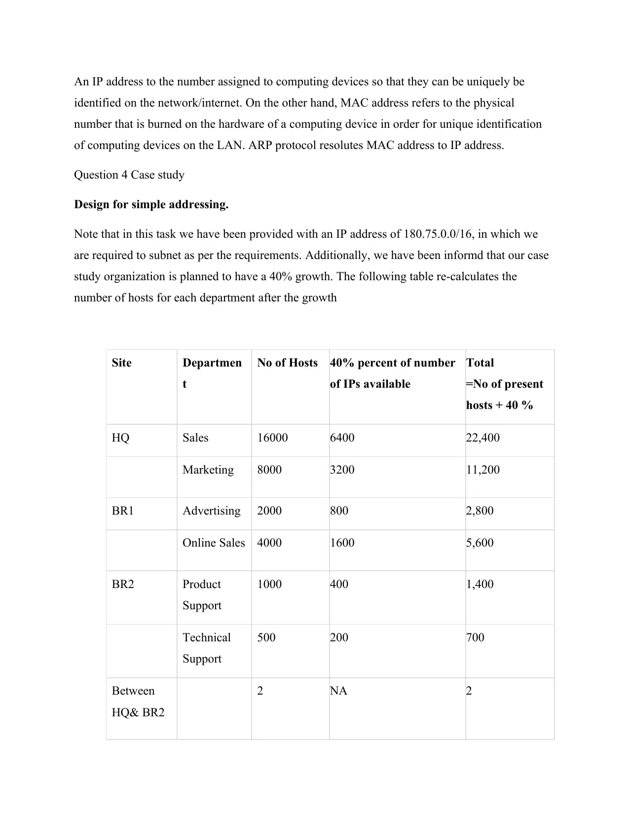
Note that in this task we have been provided with an IP address of 180.75.0.0/16, in which we
are required to subnet as per the requirements. Additionally, we have been informd that our case
study organization is planned to have a 40% growth. The following table re-calculates the
number of hosts for each department after the growth
Site Departmen
t
No of Hosts 40% percent of number
of IPs available
Total
=No of present
hosts + 40 %
HQ Sales 16000 6400 22,400
Marketing 8000 3200 11,200
BR1 Advertising 2000 800 2,800
Online Sales 4000 1600 5,600
BR2 Product
Support
1000 400 1,400
Technical
Support
500 200 700
Between
HQ& BR2
2 NA 2
identified on the network/internet. On the other hand, MAC address refers to the physical
number that is burned on the hardware of a computing device in order for unique identification
of computing devices on the LAN. ARP protocol resolutes MAC address to IP address.
Question 4 Case study
Design for simple addressing.
Note that in this task we have been provided with an IP address of 180.75.0.0/16, in which we
are required to subnet as per the requirements. Additionally, we have been informd that our case
study organization is planned to have a 40% growth. The following table re-calculates the
number of hosts for each department after the growth
Site Departmen
t
No of Hosts 40% percent of number
of IPs available
Total
=No of present
hosts + 40 %
HQ Sales 16000 6400 22,400
Marketing 8000 3200 11,200
BR1 Advertising 2000 800 2,800
Online Sales 4000 1600 5,600
BR2 Product
Support
1000 400 1,400
Technical
Support
500 200 700
Between
HQ& BR2
2 NA 2
Paraphrase This Document
Need a fresh take? Get an instant paraphrase of this document with our AI Paraphraser
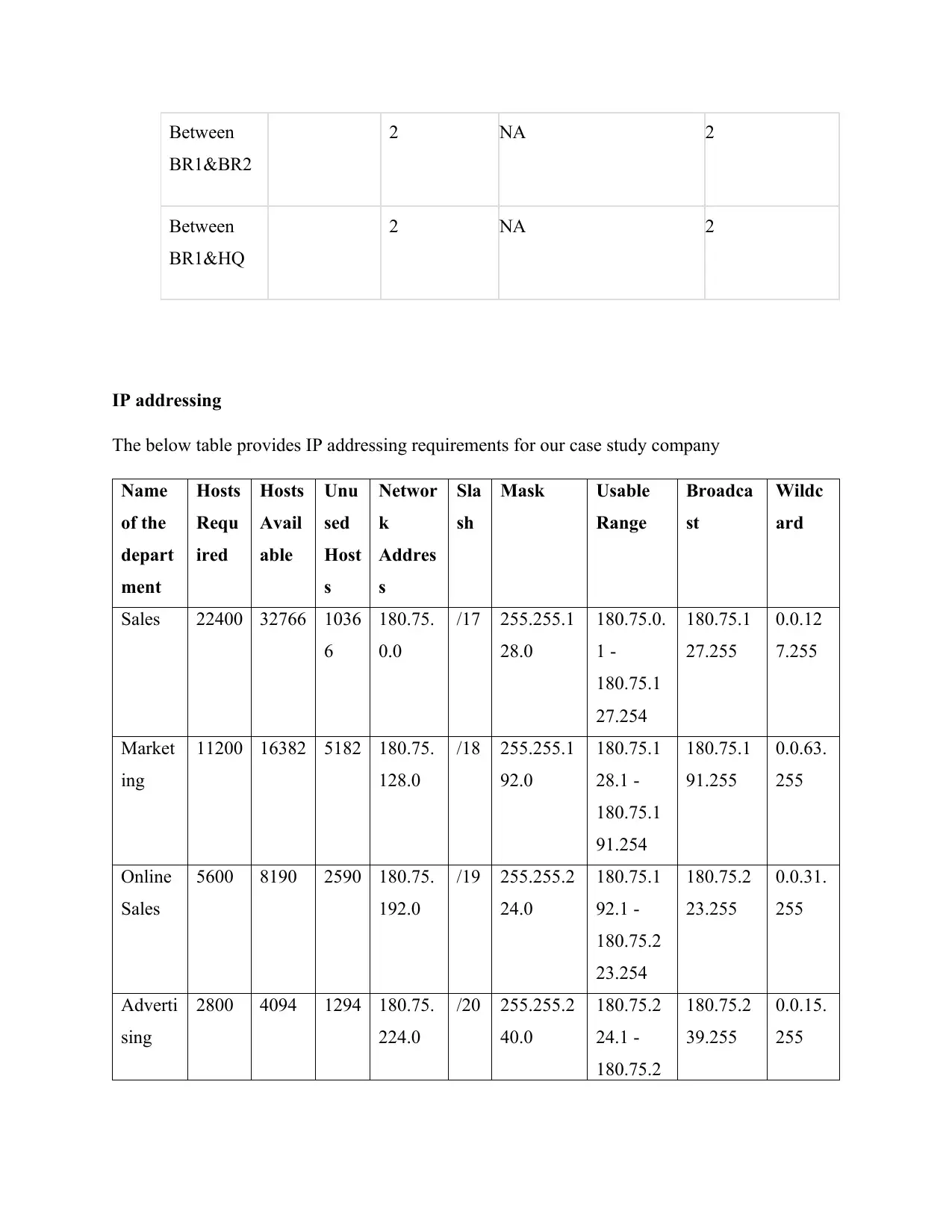
Between
BR1&BR2
2 NA 2
Between
BR1&HQ
2 NA 2
IP addressing
The below table provides IP addressing requirements for our case study company
Name
of the
depart
ment
Hosts
Requ
ired
Hosts
Avail
able
Unu
sed
Host
s
Networ
k
Addres
s
Sla
sh
Mask Usable
Range
Broadca
st
Wildc
ard
Sales 22400 32766 1036
6
180.75.
0.0
/17 255.255.1
28.0
180.75.0.
1 -
180.75.1
27.254
180.75.1
27.255
0.0.12
7.255
Market
ing
11200 16382 5182 180.75.
128.0
/18 255.255.1
92.0
180.75.1
28.1 -
180.75.1
91.254
180.75.1
91.255
0.0.63.
255
Online
Sales
5600 8190 2590 180.75.
192.0
/19 255.255.2
24.0
180.75.1
92.1 -
180.75.2
23.254
180.75.2
23.255
0.0.31.
255
Adverti
sing
2800 4094 1294 180.75.
224.0
/20 255.255.2
40.0
180.75.2
24.1 -
180.75.2
180.75.2
39.255
0.0.15.
255
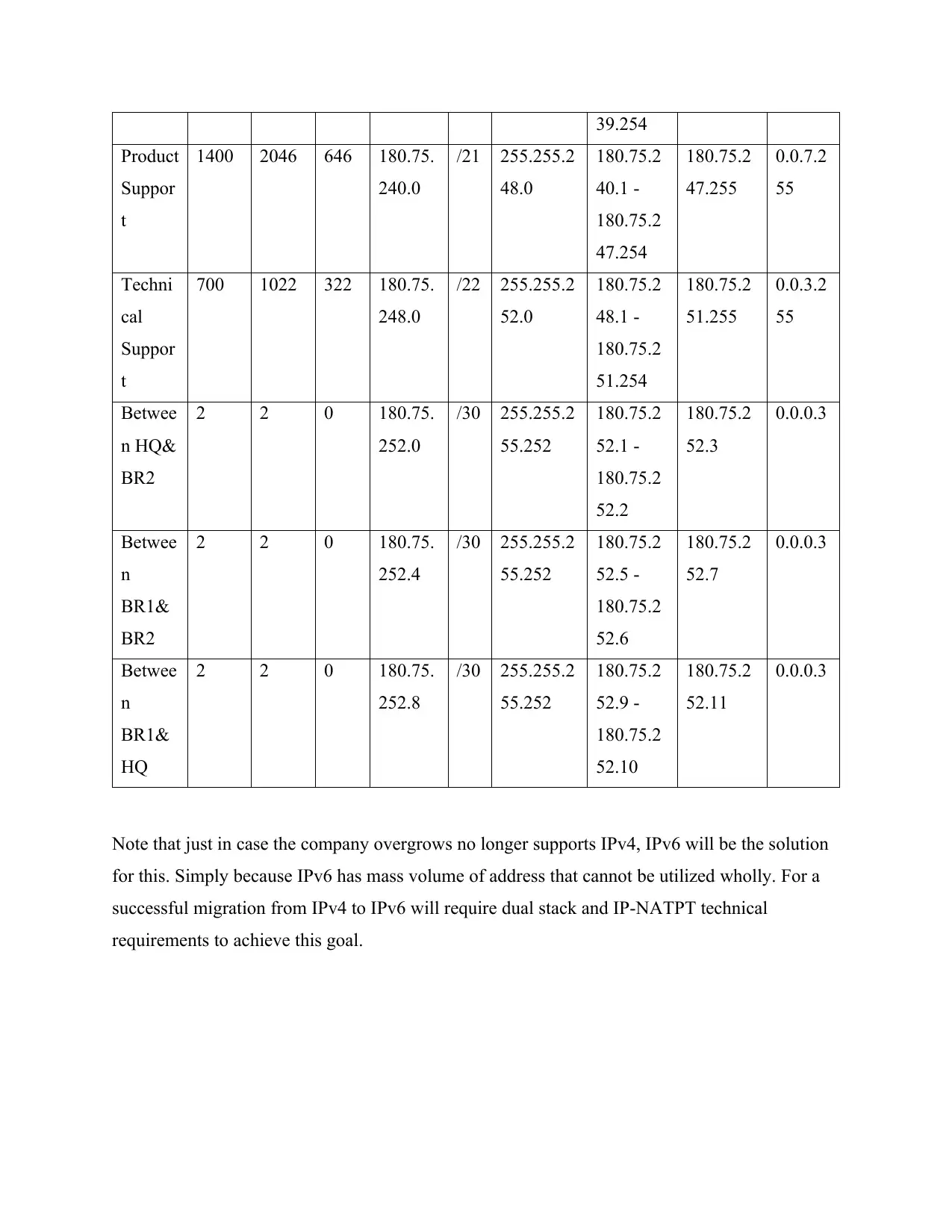
39.254
Product
Suppor
t
1400 2046 646 180.75.
240.0
/21 255.255.2
48.0
180.75.2
40.1 -
180.75.2
47.254
180.75.2
47.255
0.0.7.2
55
Techni
cal
Suppor
t
700 1022 322 180.75.
248.0
/22 255.255.2
52.0
180.75.2
48.1 -
180.75.2
51.254
180.75.2
51.255
0.0.3.2
55
Betwee
n HQ&
BR2
2 2 0 180.75.
252.0
/30 255.255.2
55.252
180.75.2
52.1 -
180.75.2
52.2
180.75.2
52.3
0.0.0.3
Betwee
n
BR1&
BR2
2 2 0 180.75.
252.4
/30 255.255.2
55.252
180.75.2
52.5 -
180.75.2
52.6
180.75.2
52.7
0.0.0.3
Betwee
n
BR1&
HQ
2 2 0 180.75.
252.8
/30 255.255.2
55.252
180.75.2
52.9 -
180.75.2
52.10
180.75.2
52.11
0.0.0.3
Note that just in case the company overgrows no longer supports IPv4, IPv6 will be the solution
for this. Simply because IPv6 has mass volume of address that cannot be utilized wholly. For a
successful migration from IPv4 to IPv6 will require dual stack and IP-NATPT technical
requirements to achieve this goal.
⊘ This is a preview!⊘
Do you want full access?
Subscribe today to unlock all pages.
Trusted by 1+ million students worldwide
1 out of 13
Related Documents


Your All-in-One AI-Powered Toolkit for Academic Success.
+13062052269
info@desklib.com
Available 24*7 on WhatsApp / Email
![[object Object]](/_next/static/media/star-bottom.7253800d.svg)
Unlock your academic potential
Copyright © 2020–2026 A2Z Services. All Rights Reserved. Developed and managed by ZUCOL.