ITC542 Internetworking with TCP/IP Assignment: Network Solutions
VerifiedAdded on  2023/01/19
|14
|2571
|62
Homework Assignment
AI Summary
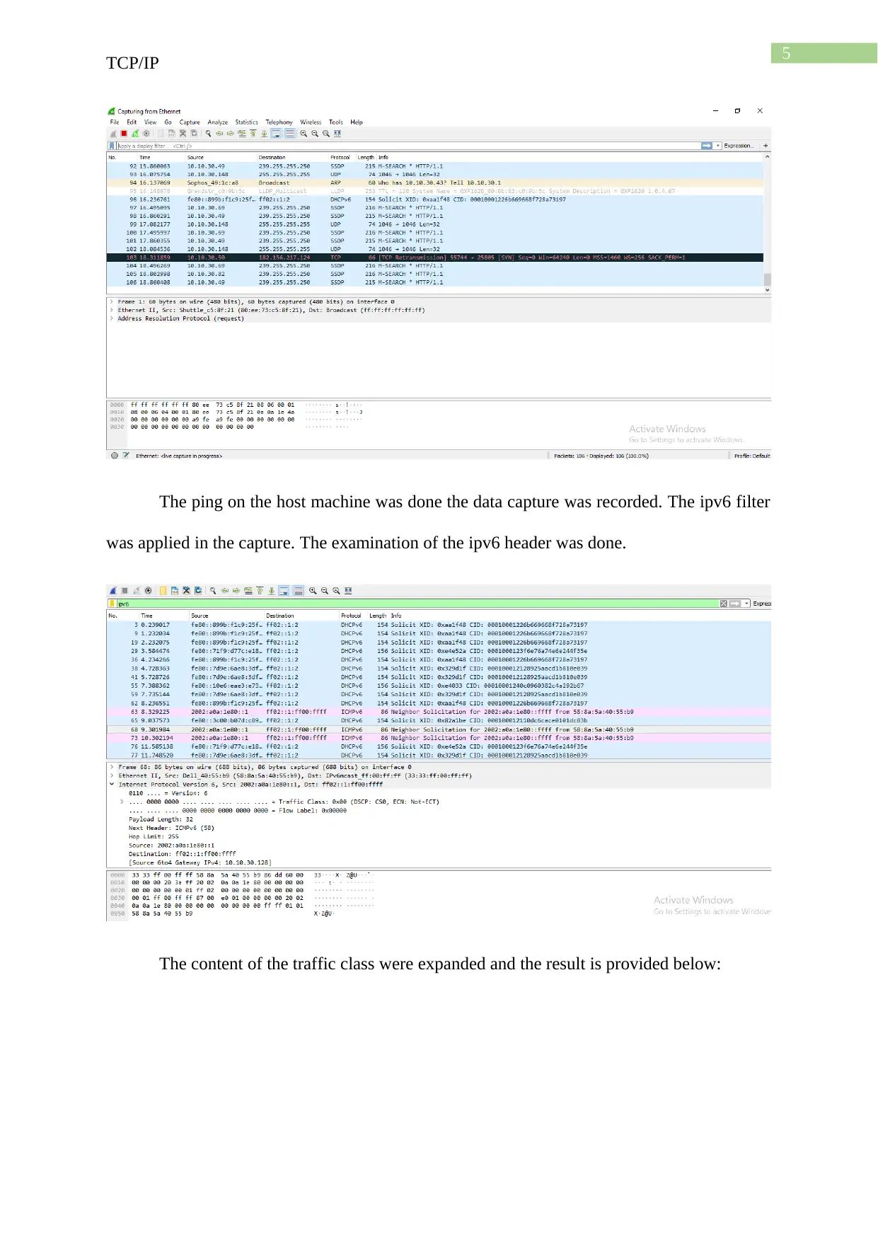
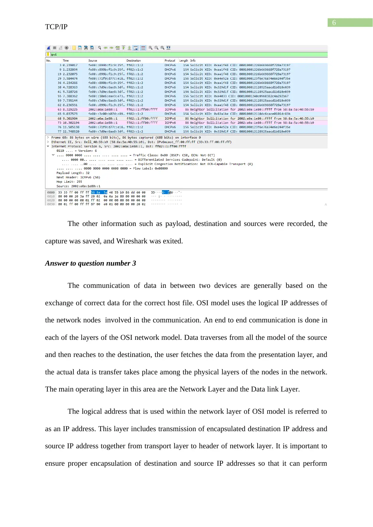
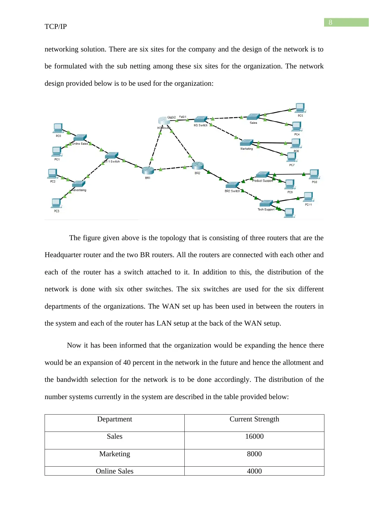
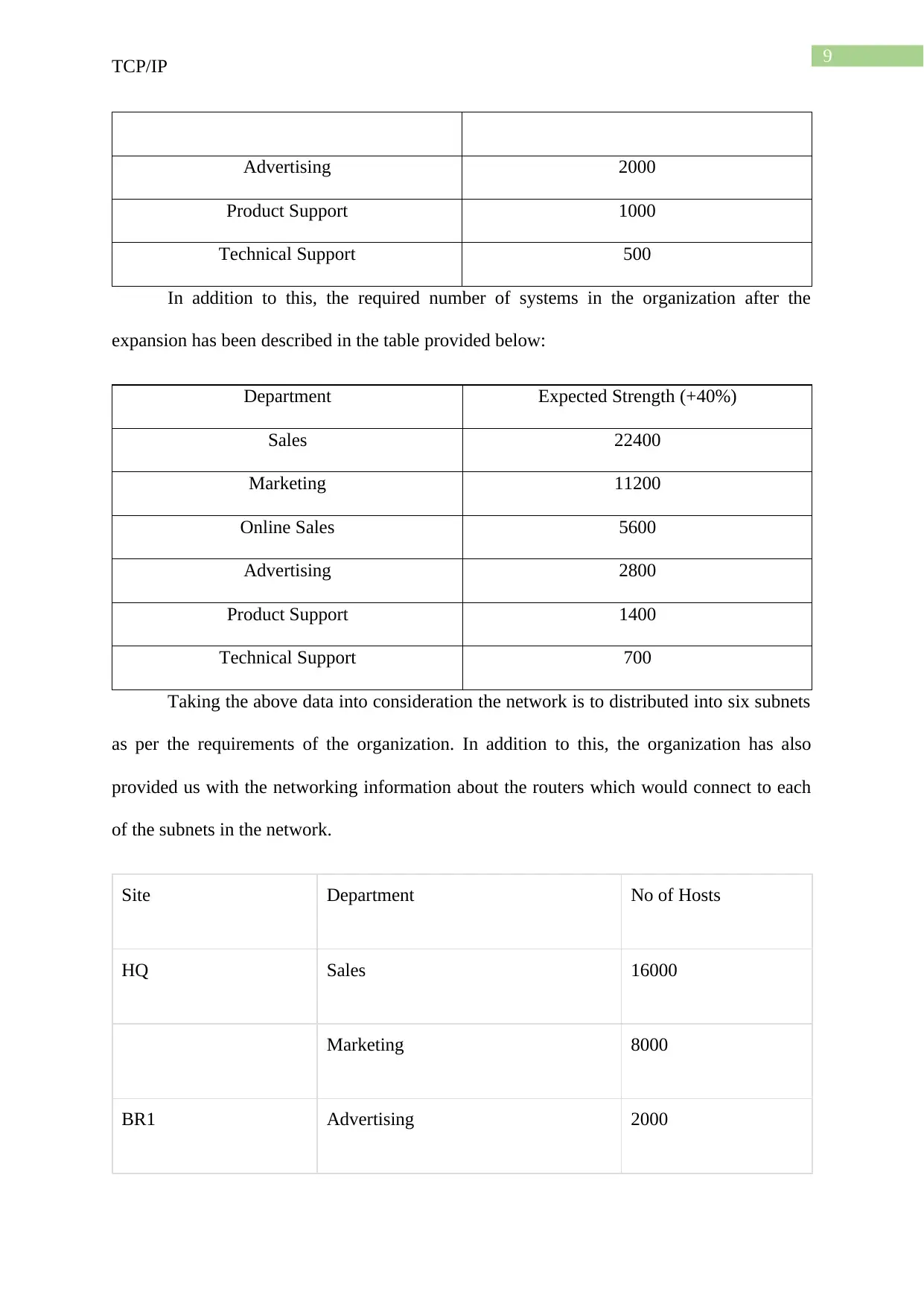
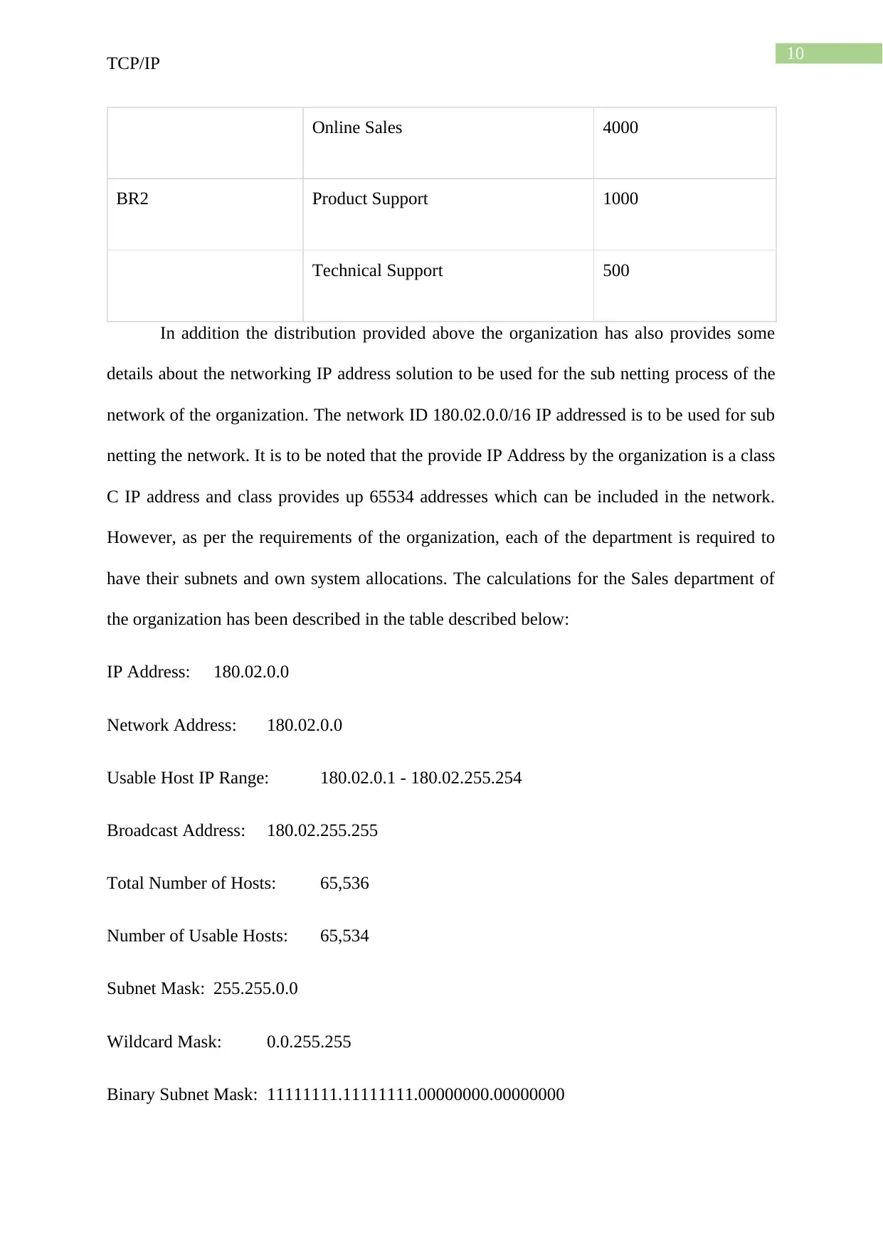
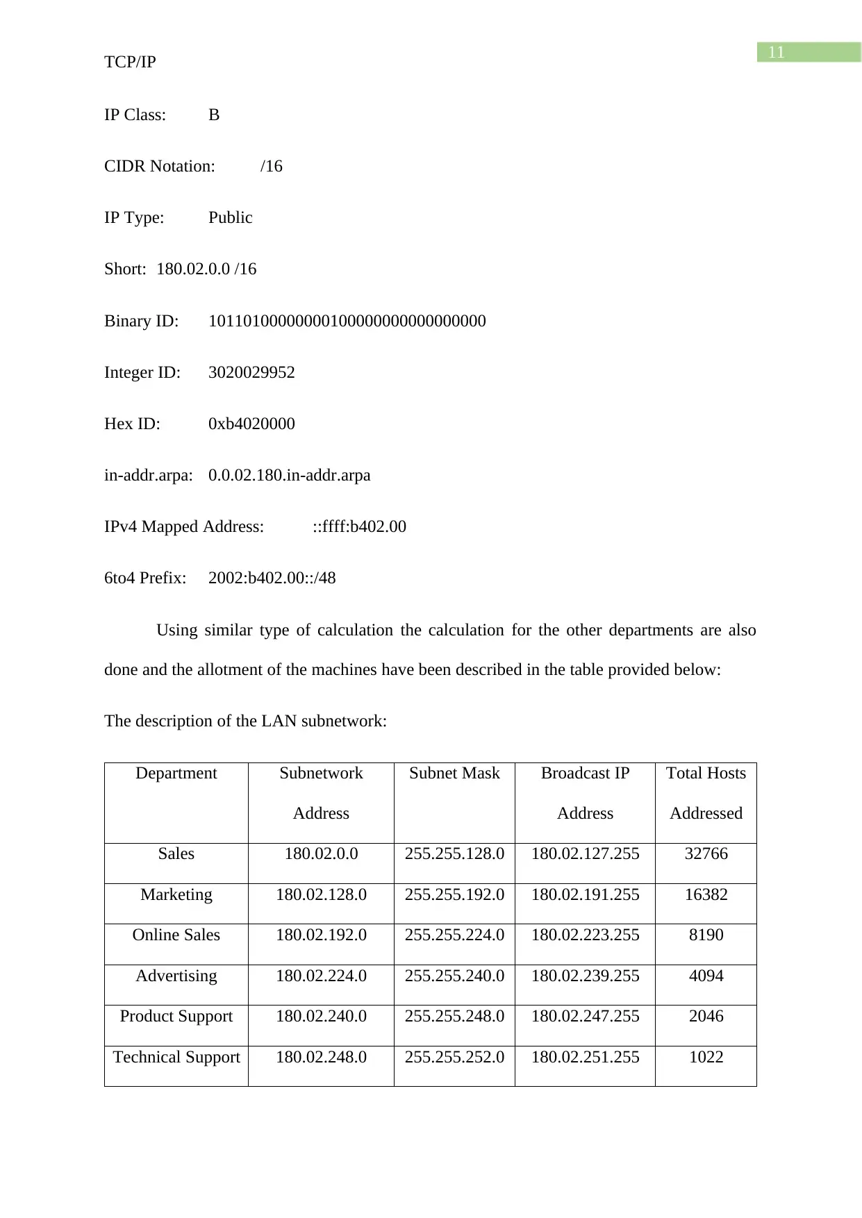
This assignment solution delves into the intricacies of TCP/IP, beginning with an overview of the OSI model and its seven layers, detailing the functions of each layer from the physical to the application layer. It then presents hands-on projects, including subnet calculations using the gestioip tool and Wireshark data capture and IPv6 header examination. The solution further explains the roles of IP and MAC addresses in network communication, including how ARP resolves MAC addresses. A significant portion of the solution is dedicated to designing a network plan for Foreshore IT Solutions, including subnetting for six departments, considering future expansion, and providing detailed calculations for IP address allocation and subnet masks. The solution also covers the WAN and LAN subnetwork design and the allocation of IP addresses for routers and subnets. The solution demonstrates the practical application of TCP/IP principles in real-world networking scenarios.

Running head: TCP/IP
TCP/IP
Name of the Student:
Name of the University:
Author Note
TCP/IP
Name of the Student:
Name of the University:
Author Note
Paraphrase This Document
Need a fresh take? Get an instant paraphrase of this document with our AI Paraphraser

1
TCP/IP
Answer to question number 1
The OSI model is used as a framework for the systematic and functional procedures
of the networking communication systems for different type of organization. The full form of
the OSI model is the Open system interconnection model. There are seven layers in the in
networking model and all the models interact with each other to get the communication
flowing through the network with efficiency. The description of each of the layer of the OSI
model is provided below:
Layer 1 – Physical layer
The physical layer is the bottommost layer of the model and all the connections in the
network are established with the help of this network. The layer maintains the raw bits of the
data for the communication. The layer establishes the networking by synchronizing the bits of
the components and creating the physical topologies.
Layer 2 – Data link layer
The data link layer works in the layer with the help of the physical addresses in the
devices. The data link layer is used for the establishing the connection in between two IP
addresses of the network. There are various type of protocols that are used in the networking
layer of network model. The Data link layers makes use of the MAC addresses of the source
machine and the destination machine and form a frame. The functions of framing the packets,
data control flow and this layer of the network model maintains access control within the
network.
Layer 3 – Network layer
The network layer is above the data link layer and the network layer performs the task
of forwarding of the packets. The layer is used for the data routing procedures of the network

2
TCP/IP
are performed at this layer in the network. The routing information are stored in this layer
and logical address binding are done at this segment of the layer.
Layer 4 – Transport layer
The transport layer is one of the main layers of the OSI network model. The middle
layer of the networking model is the network layer and the communications in the network
are performed with the use of two protocols namely the TCP or the Transmission control
protocol and the UDP protocol or the User datagram protocol. A segment of the messages
flow from the transport and the network layer encapsulates the messages in the network. The
port numbers and network services are used for the networking communications.
Segmentation and addressing of the ports are used in this network layer.
Layer 5 – Session layer
The session layer is used for the co-ordination in between the different devices that
are connected in the network. The information about the currently established networking
communication in between the two different network nodes are provided in this layer of the
network model. The dialog control functionalities and the other features of the network are
defined in this network.
Layer 6 - Presentation layer
The layer is entrusted with the functionalities of translations. This layer performs the
encryption and the decryption functionalities of the network.
Layer 7 – Application layer
The application layer is the top most layer of the OSI model and the layer is used an
interface layer, which is used for the interaction of software. The presentation layer translates
all the procedures of the Application layer.
⊘ This is a preview!⊘
Do you want full access?
Subscribe today to unlock all pages.

Trusted by 1+ million students worldwide

3
TCP/IP
Layer 7 to 5 are categories under the software layer of the OSI network model. The
layers 3 to 1 are categorised under the hardware layers. The layer categorization are done
according to the functionalities performed by each of the layers.
The internet layer is categorised as the network layer of the OSI model. The network
layer handles the logical IP addresses of the devices and this layer handles the internet
connections. Hence, the name the internet layer is suggested for the layer in the networking
model. The addition to this, in a communication in between two networking nodes exchange
of data takes place, however this is possible only if the source and the destinations of the
nodes are described properly.
Answer to question number 2
Hands On project 2.3
Paraphrase This Document
Need a fresh take? Get an instant paraphrase of this document with our AI Paraphraser

4
TCP/IP
The browser is accessed and the gestioip is visited. The address 192.168.0.0 is used
for calculating the subnet. The result of the calculation is provided below:
The range of the hosts and the other in formations such as subnetwork, subnet mask
and broadcast is show.
Hands On project 3.2
The Wireshark application was started for the capture of data on the system.

5
TCP/IP
The ping on the host machine was done the data capture was recorded. The ipv6 filter
was applied in the capture. The examination of the ipv6 header was done.
The content of the traffic class were expanded and the result is provided below:
TCP/IP
The ping on the host machine was done the data capture was recorded. The ipv6 filter
was applied in the capture. The examination of the ipv6 header was done.
The content of the traffic class were expanded and the result is provided below:
⊘ This is a preview!⊘
Do you want full access?
Subscribe today to unlock all pages.

Trusted by 1+ million students worldwide

6
TCP/IP
The other information such as payload, destination and sources were recorded, the
capture was saved, and Wireshark was exited.
Answer to question number 3
The communication of data in between two devices are generally based on the
exchange of correct data for the correct host file. OSI model uses the logical IP addresses of
the network nodes involved in the communication. An end to end communication is done in
each of the layers of the OSI network model. Data traverses from all the model of the source
and then reaches to the destination, the user fetches the data from the presentation layer, and
the actual data is transfer takes place among the physical layers of the nodes in the network.
The main operating layer in this area are the Network Layer and the Data link Layer.
The logical address that is used within the network layer of OSI model is referred to
as an IP address. This layer includes transmission of encapsulated destination IP address and
source IP address together from transport layer to header of network layer. It is important to
ensure proper encapsulation of destination and source IP addresses so that it can perform
Paraphrase This Document
Need a fresh take? Get an instant paraphrase of this document with our AI Paraphraser

7
TCP/IP
proper activity. In addition to this IP address plays a vital role in managing the routing
decision. The major routing protocols that are offered within this layer include RIP, BGP,
static and many more. This is used for the purpose of making specific routing decision
towards the packets.
The aim of MAC address is to have a proper physical address of the devices. This are
referred to as the most important part of data link layer. MAC addresses are mainly used by
ARP protocol. The main reason of using MAC address is to encapsulate the functions and
processes related to the access control. This helps in forwarding the packet from network
layer. The encapsulation for this layer includes layer header, source MAC address and
destination MAC address. This encapsulated material is forwarded from network layer. It is
impossible to transfer the information from source MAC address to destination MAC address
if proper encapsulation is not performed.
Address resolution protocol is a 2 layered protocol that aims at resolving the unknown
MAC address based on the request provided by users. The users provide IP address for which
the MAC address is being identified. It is observed that not all time the destination MAC
address is acknowledged. In such cases ARP focuses on resolving the issue and tries to
generate respective MAC address for the provided destination IP address. After this the
protocol retrieves the MAC address than it is being stored within the MAC table for the
requested IP address. It is important for every device to have a proper MAC address and IP
address so that they get connected to other devices.
Answer to question number 4
The Network plan for the Foreshore IT Solutions have be developed. The
organization already consist of a network plan however the rate of expansion for the
organization is very high and hence the organization would be required to relay their

8
TCP/IP
networking solution. There are six sites for the company and the design of the network is to
be formulated with the sub netting among these six sites for the organization. The network
design provided below is to be used for the organization:
The figure given above is the topology that is consisting of three routers that are the
Headquarter router and the two BR routers. All the routers are connected with each other and
each of the router has a switch attached to it. In addition to this, the distribution of the
network is done with six other switches. The six switches are used for the six different
departments of the organizations. The WAN set up has been used in between the routers in
the system and each of the router has LAN setup at the back of the WAN setup.
Now it has been informed that the organization would be expanding the hence there
would be an expansion of 40 percent in the network in the future and hence the allotment and
the bandwidth selection for the network is to be done accordingly. The distribution of the
number systems currently in the system are described in the table provided below:
Department Current Strength
Sales 16000
Marketing 8000
Online Sales 4000
⊘ This is a preview!⊘
Do you want full access?
Subscribe today to unlock all pages.

Trusted by 1+ million students worldwide

9
TCP/IP
Advertising 2000
Product Support 1000
Technical Support 500
In addition to this, the required number of systems in the organization after the
expansion has been described in the table provided below:
Department Expected Strength (+40%)
Sales 22400
Marketing 11200
Online Sales 5600
Advertising 2800
Product Support 1400
Technical Support 700
Taking the above data into consideration the network is to distributed into six subnets
as per the requirements of the organization. In addition to this, the organization has also
provided us with the networking information about the routers which would connect to each
of the subnets in the network.
Site Department No of Hosts
HQ Sales 16000
Marketing 8000
BR1 Advertising 2000
Paraphrase This Document
Need a fresh take? Get an instant paraphrase of this document with our AI Paraphraser

10
TCP/IP
Online Sales 4000
BR2 Product Support 1000
Technical Support 500
In addition the distribution provided above the organization has also provides some
details about the networking IP address solution to be used for the sub netting process of the
network of the organization. The network ID 180.02.0.0/16 IP addressed is to be used for sub
netting the network. It is to be noted that the provide IP Address by the organization is a class
C IP address and class provides up 65534 addresses which can be included in the network.
However, as per the requirements of the organization, each of the department is required to
have their subnets and own system allocations. The calculations for the Sales department of
the organization has been described in the table described below:
IP Address: 180.02.0.0
Network Address: 180.02.0.0
Usable Host IP Range: 180.02.0.1 - 180.02.255.254
Broadcast Address: 180.02.255.255
Total Number of Hosts: 65,536
Number of Usable Hosts: 65,534
Subnet Mask: 255.255.0.0
Wildcard Mask: 0.0.255.255
Binary Subnet Mask: 11111111.11111111.00000000.00000000

11
TCP/IP
IP Class: B
CIDR Notation: /16
IP Type: Public
Short: 180.02.0.0 /16
Binary ID: 10110100000000100000000000000000
Integer ID: 3020029952
Hex ID: 0xb4020000
in-addr.arpa: 0.0.02.180.in-addr.arpa
IPv4 Mapped Address: ::ffff:b402.00
6to4 Prefix: 2002:b402.00::/48
Using similar type of calculation the calculation for the other departments are also
done and the allotment of the machines have been described in the table provided below:
The description of the LAN subnetwork:
Department Subnetwork
Address
Subnet Mask Broadcast IP
Address
Total Hosts
Addressed
Sales 180.02.0.0 255.255.128.0 180.02.127.255 32766
Marketing 180.02.128.0 255.255.192.0 180.02.191.255 16382
Online Sales 180.02.192.0 255.255.224.0 180.02.223.255 8190
Advertising 180.02.224.0 255.255.240.0 180.02.239.255 4094
Product Support 180.02.240.0 255.255.248.0 180.02.247.255 2046
Technical Support 180.02.248.0 255.255.252.0 180.02.251.255 1022
⊘ This is a preview!⊘
Do you want full access?
Subscribe today to unlock all pages.

Trusted by 1+ million students worldwide
1 out of 14
Related Documents

Your All-in-One AI-Powered Toolkit for Academic Success.
 +13062052269
info@desklib.com
Available 24*7 on WhatsApp / Email
Unlock your academic potential
Copyright © 2020–2025 A2Z Services. All Rights Reserved. Developed and managed by ZUCOL.