Institution: Network Design and Configuration - TCP/IP Report

Verified

Added on  2022/10/13

|13
|1214
|13
Report
AI Summary
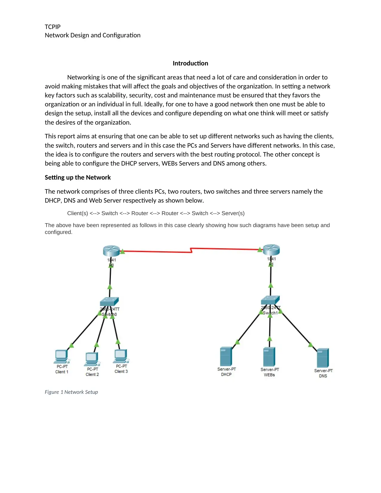
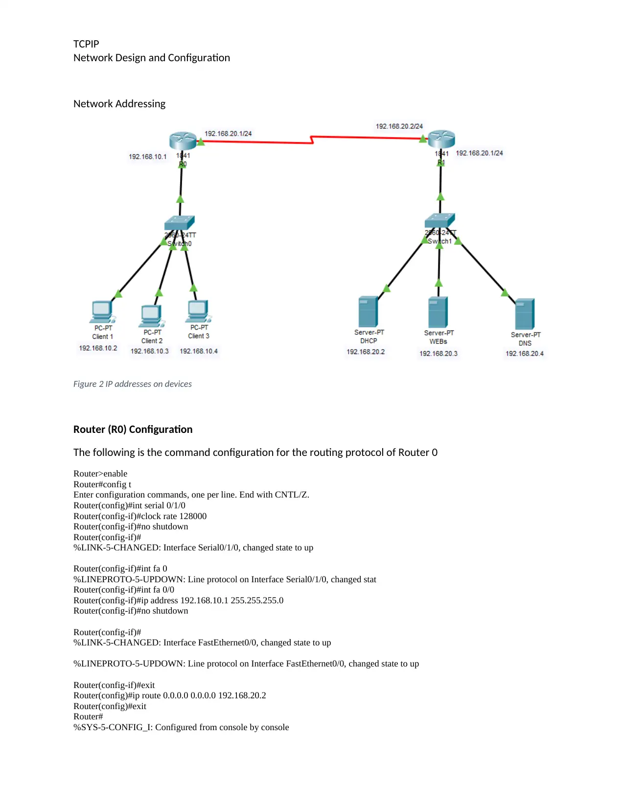
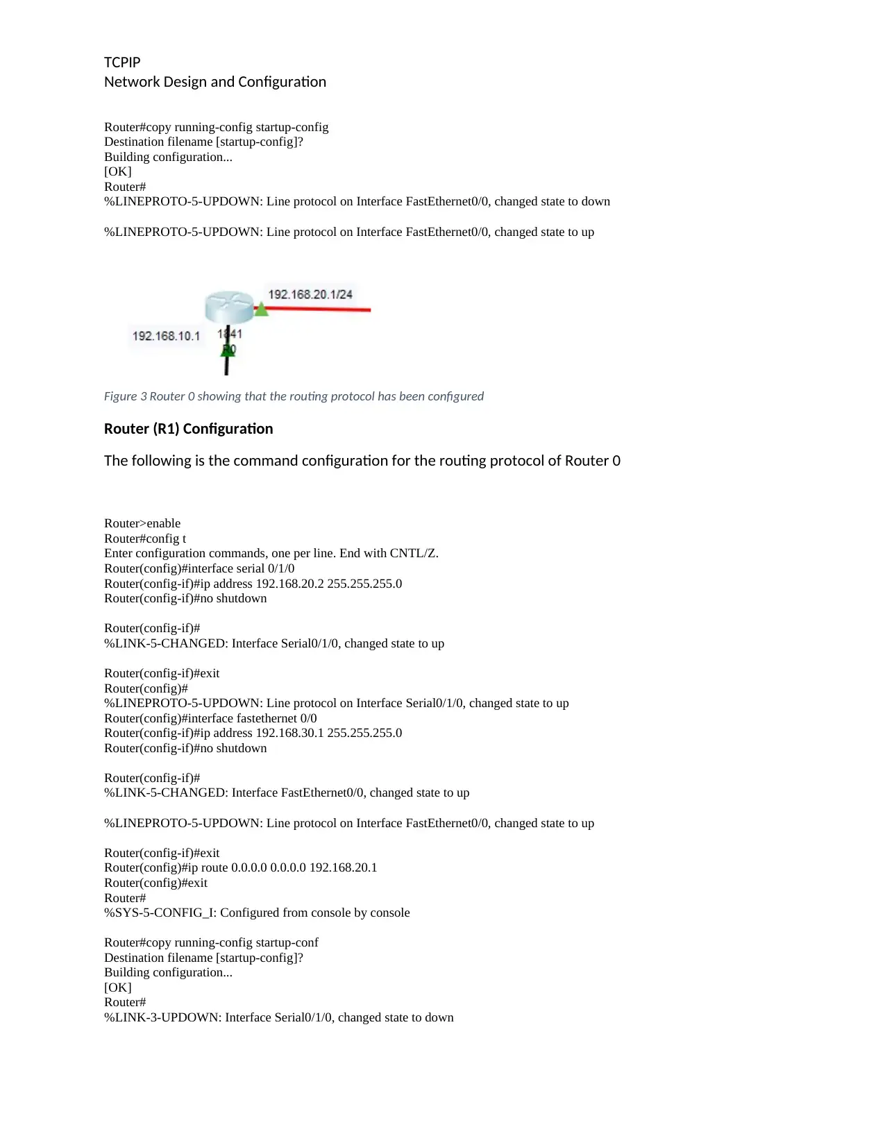
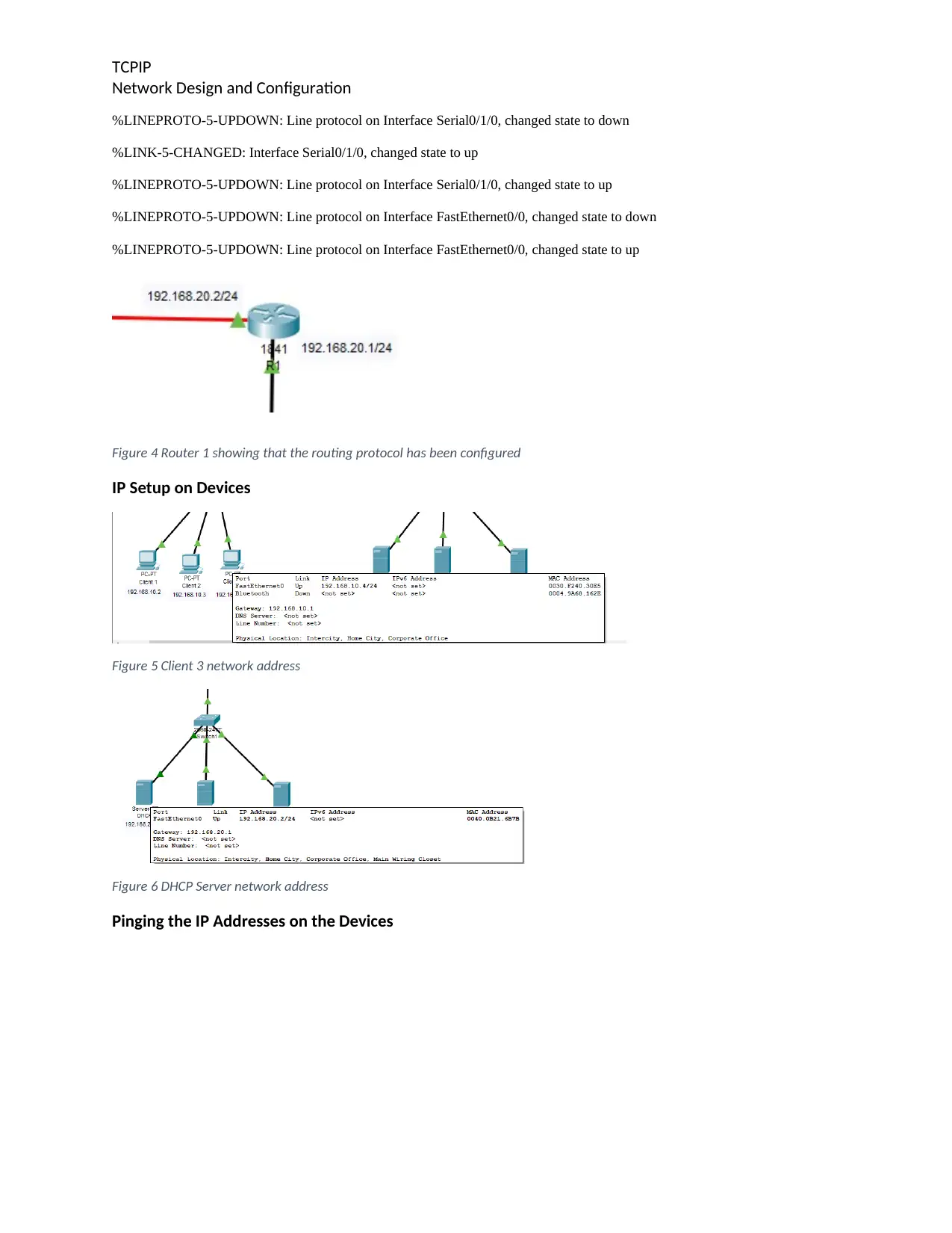
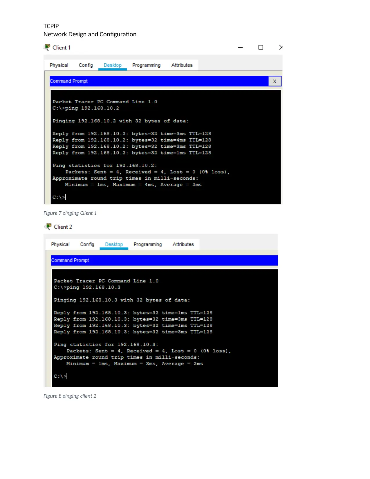
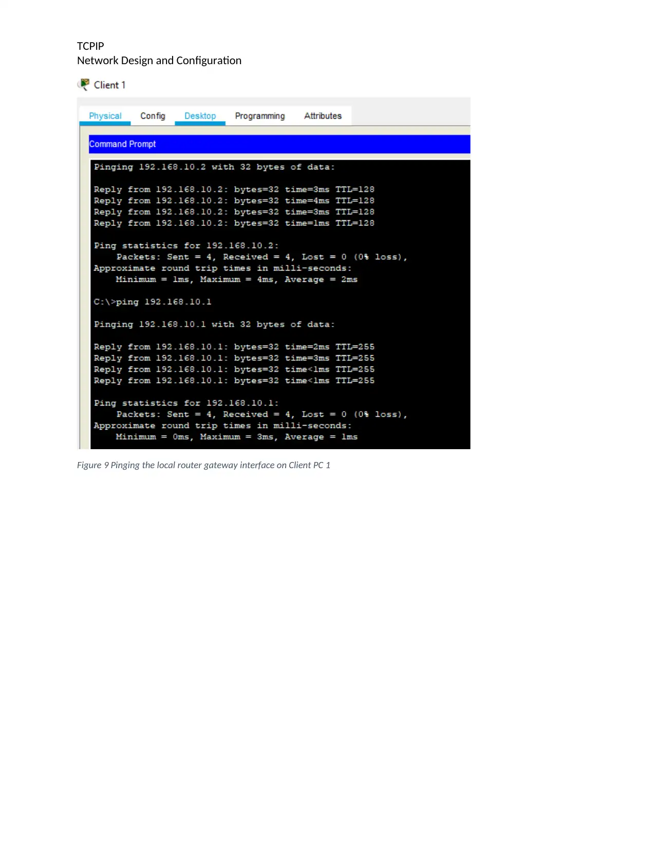
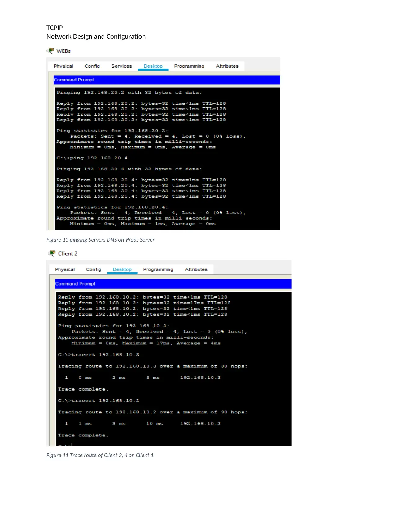
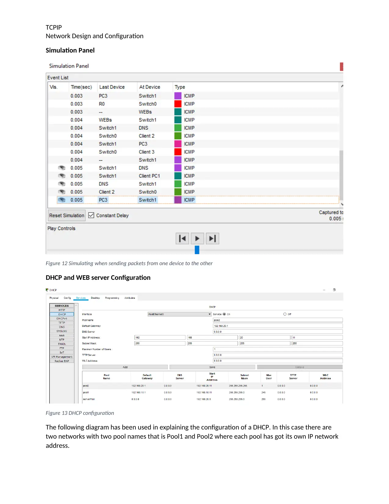
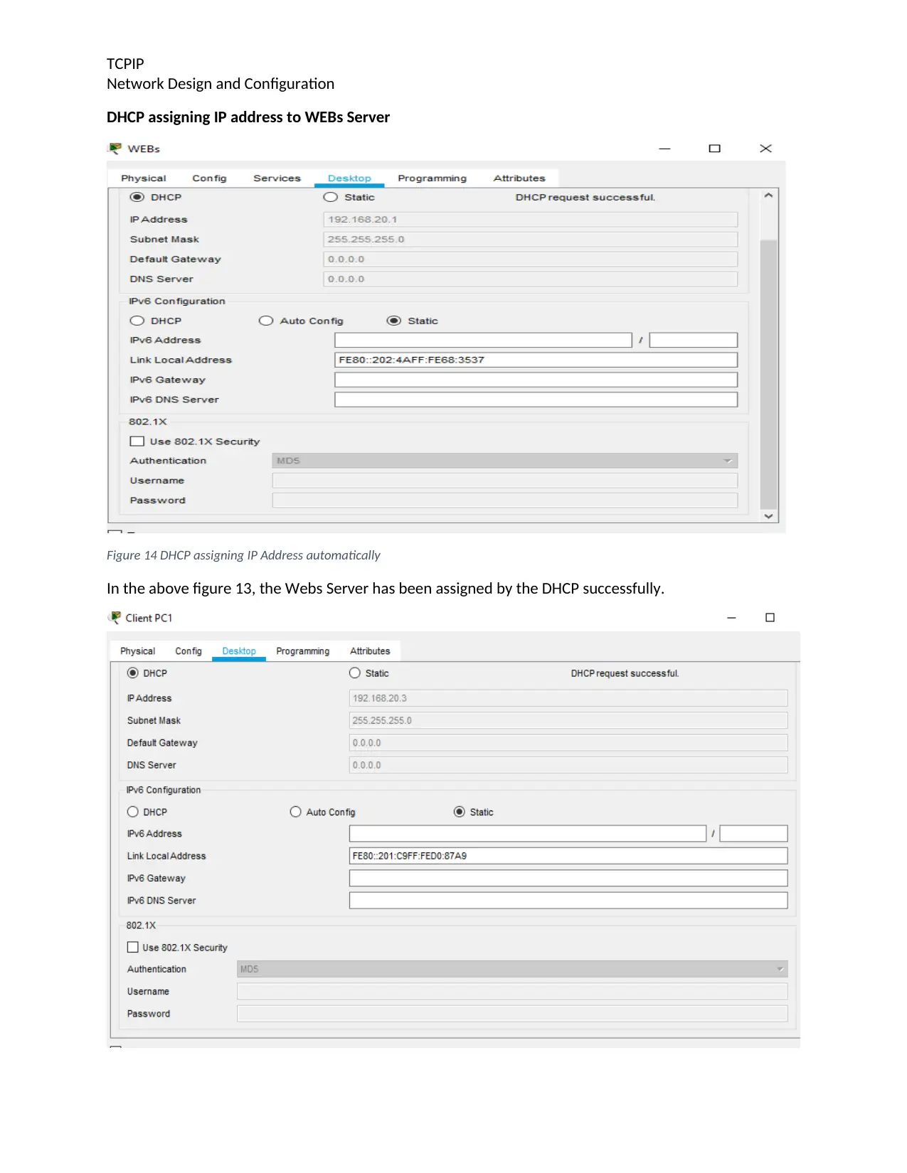
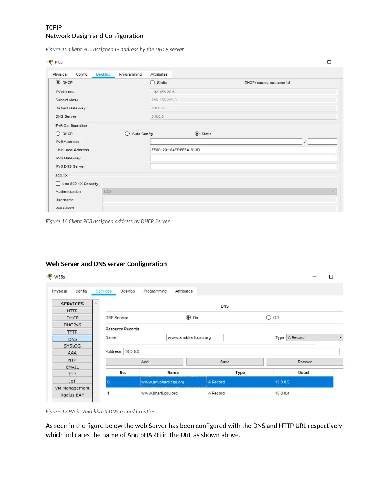
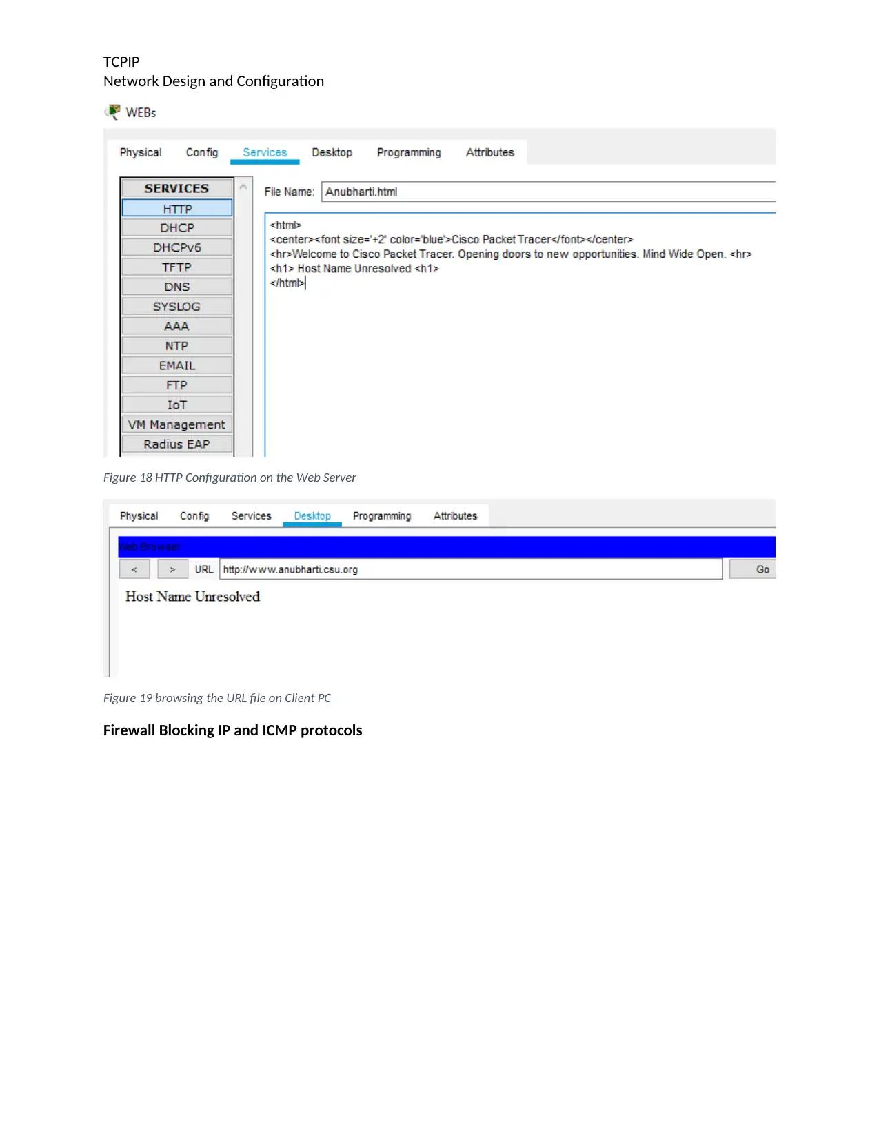
This report presents a comprehensive overview of a TCP/IP network design and configuration. The network comprises three client PCs, two routers, two switches, and three servers (DHCP, DNS, and Web Server). The report details the configuration of routers, including routing protocols, and the setup of IP addresses for all devices. It includes command configurations for routers (R0 and R1), along with network addressing diagrams. The report explains DHCP and Web server configurations, including the assignment of IP addresses by the DHCP server, DNS record creation, and HTTP configuration on the Web Server. It also includes ping tests, trace route tests, and simulation panel results to demonstrate network communication. The report concludes that the network is functioning correctly, with devices communicating effectively across different networks, ensuring scalability and security through firewall implementation.
Document Page
TCPIP
Network Design and Configuration
Student Name
Course Name
TCP/IP Networking
Network Design and Configuration
Institutional Affiliation(s)
tabler-icon-diamond-filled.svg

Secure Best Marks with AI Grader

Need help grading? Try our AI Grader for instant feedback on your assignments.
Document Page
TCPIP
Network Design and Configuration
Introduction
Networking is one of the significant areas that need a lot of care and consideration in order to
avoid making mistakes that will affect the goals and objectives of the organization. In setting a network
key factors such as scalability, security, cost and maintenance must be ensured that they favors the
organization or an individual in full. Ideally, for one to have a good network then one must be able to
design the setup, install all the devices and configure depending on what one think will meet or satisfy
the desires of the organization.
This report aims at ensuring that one can be able to set up different networks such as having the clients,
the switch, routers and servers and in this case the PCs and Servers have different networks. In this case,
the idea is to configure the routers and servers with the best routing protocol. The other concept is
being able to configure the DHCP servers, WEBs Servers and DNS among others.
Setting up the Network
The network comprises of three clients PCs, two routers, two switches and three servers namely the
DHCP, DNS and Web Server respectively as shown below.
Client(s) <--> Switch <--> Router <--> Router <--> Switch <--> Server(s)
The above have been represented as follows in this case clearly showing how such diagrams have been setup and
configured.
Figure 1 Network Setup
Document Page
TCPIP
Network Design and Configuration
Network Addressing
Figure 2 IP addresses on devices
Router (R0) Configuration
The following is the command configuration for the routing protocol of Router 0
Router>enable
Router#config t
Enter configuration commands, one per line. End with CNTL/Z.
Router(config)#int serial 0/1/0
Router(config-if)#clock rate 128000
Router(config-if)#no shutdown
Router(config-if)#
%LINK-5-CHANGED: Interface Serial0/1/0, changed state to up
Router(config-if)#int fa 0
%LINEPROTO-5-UPDOWN: Line protocol on Interface Serial0/1/0, changed stat
Router(config-if)#int fa 0/0
Router(config-if)#ip address 192.168.10.1 255.255.255.0
Router(config-if)#no shutdown
Router(config-if)#
%LINK-5-CHANGED: Interface FastEthernet0/0, changed state to up
%LINEPROTO-5-UPDOWN: Line protocol on Interface FastEthernet0/0, changed state to up
Router(config-if)#exit
Router(config)#ip route 0.0.0.0 0.0.0.0 192.168.20.2
Router(config)#exit
Router#
%SYS-5-CONFIG_I: Configured from console by console
Document Page
TCPIP
Network Design and Configuration
Router#copy running-config startup-config
Destination filename [startup-config]?
Building configuration...
[OK]
Router#
%LINEPROTO-5-UPDOWN: Line protocol on Interface FastEthernet0/0, changed state to down
%LINEPROTO-5-UPDOWN: Line protocol on Interface FastEthernet0/0, changed state to up
Figure 3 Router 0 showing that the routing protocol has been configured
Router (R1) Configuration
The following is the command configuration for the routing protocol of Router 0
Router>enable
Router#config t
Enter configuration commands, one per line. End with CNTL/Z.
Router(config)#interface serial 0/1/0
Router(config-if)#ip address 192.168.20.2 255.255.255.0
Router(config-if)#no shutdown
Router(config-if)#
%LINK-5-CHANGED: Interface Serial0/1/0, changed state to up
Router(config-if)#exit
Router(config)#
%LINEPROTO-5-UPDOWN: Line protocol on Interface Serial0/1/0, changed state to up
Router(config)#interface fastethernet 0/0
Router(config-if)#ip address 192.168.30.1 255.255.255.0
Router(config-if)#no shutdown
Router(config-if)#
%LINK-5-CHANGED: Interface FastEthernet0/0, changed state to up
%LINEPROTO-5-UPDOWN: Line protocol on Interface FastEthernet0/0, changed state to up
Router(config-if)#exit
Router(config)#ip route 0.0.0.0 0.0.0.0 192.168.20.1
Router(config)#exit
Router#
%SYS-5-CONFIG_I: Configured from console by console
Router#copy running-config startup-conf
Destination filename [startup-config]?
Building configuration...
[OK]
Router#
%LINK-3-UPDOWN: Interface Serial0/1/0, changed state to down
tabler-icon-diamond-filled.svg

Secure Best Marks with AI Grader

Need help grading? Try our AI Grader for instant feedback on your assignments.
Document Page
TCPIP
Network Design and Configuration
%LINEPROTO-5-UPDOWN: Line protocol on Interface Serial0/1/0, changed state to down
%LINK-5-CHANGED: Interface Serial0/1/0, changed state to up
%LINEPROTO-5-UPDOWN: Line protocol on Interface Serial0/1/0, changed state to up
%LINEPROTO-5-UPDOWN: Line protocol on Interface FastEthernet0/0, changed state to down
%LINEPROTO-5-UPDOWN: Line protocol on Interface FastEthernet0/0, changed state to up
Figure 4 Router 1 showing that the routing protocol has been configured
IP Setup on Devices
Figure 5 Client 3 network address
Figure 6 DHCP Server network address
Pinging the IP Addresses on the Devices
Document Page
TCPIP
Network Design and Configuration
Figure 7 pinging Client 1
Figure 8 pinging client 2
Document Page
TCPIP
Network Design and Configuration
Figure 9 Pinging the local router gateway interface on Client PC 1
tabler-icon-diamond-filled.svg

Paraphrase This Document

Need a fresh take? Get an instant paraphrase of this document with our AI Paraphraser
Document Page
TCPIP
Network Design and Configuration
Figure 10 pinging Servers DNS on Webs Server
Figure 11 Trace route of Client 3, 4 on Client 1
Document Page
TCPIP
Network Design and Configuration
Simulation Panel
Figure 12 Simulating when sending packets from one device to the other
DHCP and WEB server Configuration
Figure 13 DHCP configuration
The following diagram has been used in explaining the configuration of a DHCP. In this case there are
two networks with two pool names that is Pool1 and Pool2 where each pool has got its own IP network
address.
Document Page
TCPIP
Network Design and Configuration
DHCP assigning IP address to WEBs Server
Figure 14 DHCP assigning IP Address automatically
In the above figure 13, the Webs Server has been assigned by the DHCP successfully.
tabler-icon-diamond-filled.svg

Secure Best Marks with AI Grader

Need help grading? Try our AI Grader for instant feedback on your assignments.
Document Page
TCPIP
Network Design and Configuration
Figure 15 Client PC1 assigned IP address by the DHCP server
Figure 16 Client PC3 assigned address by DHCP Server
Web Server and DNS server Configuration
Figure 17 Webs Anu bharti DNS record Creation
As seen in the figure below the web Server has been configured with the DNS and HTTP URL respectively
which indicates the name of Anu bHARTi in the URL as shown above.
Document Page
TCPIP
Network Design and Configuration
Figure 18 HTTP Configuration on the Web Server
Figure 19 browsing the URL file on Client PC
Firewall Blocking IP and ICMP protocols
Document Page
TCPIP
Network Design and Configuration
Figure 20 Denying IP Address to connect in Client PC 2
Figure 21 allowing ICMP to connect in Client PC 3
Conclusion
As seen from above it is true to say that the network are communicating with each other and that one
can send information from device to the other in different networks as clearly shown above. As shown in
the ping test and trace route test it is very much clear that the PCS are communicating clearly with the
servers. In this case, it will be true to say that all the devices are connecting efficiently in all essences and
that the network will be scalable in all ways in case there is need for expansion in future. Use of firewalls
on the web server will help in filtering the traffic the https files and thus ensuring that there is security in
the system.
chevron_up_icon
1 out of 13
circle_padding
hide_on_mobile
zoom_out_icon
[object Object]