Telecommunication Principles: Waveform Analysis, Modulation & MATLAB

Verified

Added on  2023/06/14

|11
|1701
|235
Homework Assignment
AI Summary
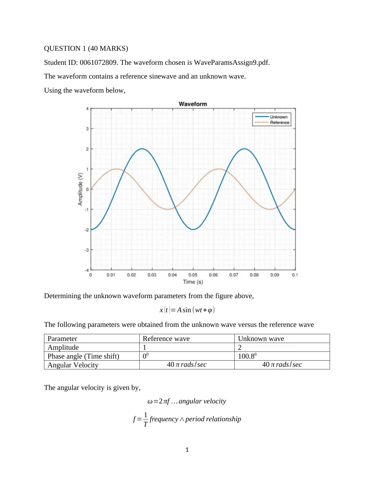
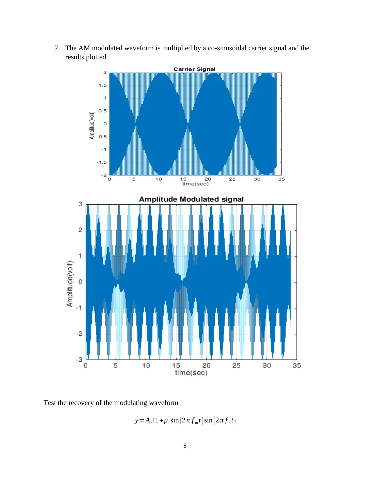
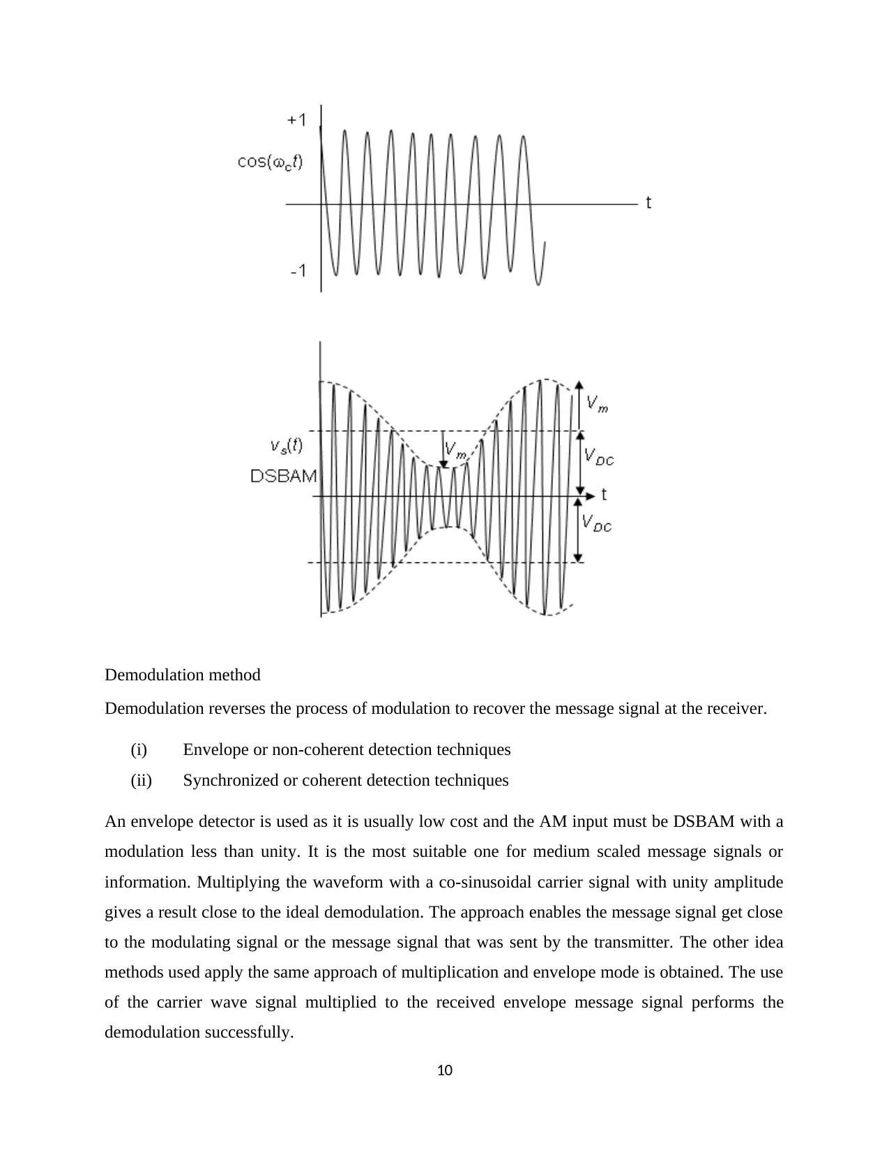
This assignment delves into telecommunication principles, focusing on waveform analysis and amplitude modulation (AM). It involves extracting parameters from a given waveform, including amplitude, phase angle, and angular velocity, and applying these parameters to construct mathematical representations of unknown waves. The assignment further explores amplitude modulation, calculating the modulation index and analyzing the relationship between message and carrier signals. Practical implementation using MATLAB is demonstrated, showcasing the generation and analysis of modulated waveforms. The assignment also investigates demodulation techniques, particularly focusing on the use of a co-sinusoidal carrier signal for recovering the original message signal, highlighting the importance of demodulation in reversing the modulation process at the receiver end. This document is available on Desklib, a platform offering a range of study tools and solved assignments for students.
Document Page
UNIVERSITY AFFILIATION
FACULTY OR DEPARTMENT
COURSE ID AND COURSE NAME
TITLE:
TELECOMMUNICATION PRINCIPLES ASSIGMENT I
STUDENT NAME
STUDENT REGISTRATION NUMBER
PROFESSOR (TUTOR)
DATE OF SUBMISSION
tabler-icon-diamond-filled.svg

Paraphrase This Document

Need a fresh take? Get an instant paraphrase of this document with our AI Paraphraser
Document Page
QUESTION 1 (40 MARKS)
Student ID: 0061072809. The waveform chosen is WaveParamsAssign9.pdf.
The waveform contains a reference sinewave and an unknown wave.
Using the waveform below,
Determining the unknown waveform parameters from the figure above,
x (t )= A sin (wt + φ)
The following parameters were obtained from the unknown wave versus the reference wave
Parameter Reference wave Unknown wave
Amplitude 1 2
Phase angle (Time shift) 00 100.80
Angular Velocity 40 π rads /sec 40 π rads /sec
The angular velocity is given by,
ω=2 πf angular velocity
f = 1
T frequency period relationship
1
Document Page
f = 1
0.05 =20 Hertz
ω=2π20
ω=40 π rads /sec
When the sine wave fails to pass through zero at the entry point, it is considered to have a phase
difference. The phase difference can be expressed as a time shift based on the period in seconds.
The common or standard mode of expressing it is done in angular measurements.
The time shift is given as,
Time shift=0.012 seconds
1 T =0.04 seconds ( fullcycle )
full cycle=3600
¿ 0.05 s 3600 ; 0.014 s ?
3600 x 0.014
0.05 =90.80 . phase angle
The phase offset or the phase difference of the unknown wave is given as 100.80.
The reference signal is given as,
x ( t ) =sin ( 40 π ) volts
The resulting equation of the unknown waveform is,
x (t )=2sin ( 40 π 90.80 ) volts
QUESTION 2 (40 MARKS)
Amplitude modulated waveform
The waveform used is AMassign9.pdf.
The amplitude modulation is used in the transfer of voice information from one place to another.
The voice frequencies are said to range from 50Hz to 3000Hz. Amplitude modulation receives
voice frequencies and mixes them with some radio frequency signals. In this form, they can
easily be converted to radio frequencies that will radiate or propagate through free space.
The modulated signal is a simple sinusoid of the form,
2
Document Page
m ( t ) =Am sin ( ωm t )
The AM waveform is then described by
x AM ( t ) = Ac sin ωm t + Am sin ( ωm t ) sin ( ωc t )
x AM ( t )= Ac ( 1+ μ sin ωm t ) sin ωc t
The modulation index is given by,
μ= Am
Ac
From a quick view of the waveform, one can settle on roughly 50 percent modulation. The
modulation index is the measure based on the ratio of the modulation excursions of the radio
frequency signal to the extent of the unmodulated carrier. It is given based on the message wave
envelope and the carrier wave form signal,
μ=50 %
Using time shift,
T =1.7 seconds ( period )
To get the angular velocity of the message envelope,
f = 1
T = 1
1.7 =0.588235 Hz
ω=2πf
ω=20.588235π
ω=1.176 π rad /sec
Parameter Message signal Carrier signal
Amplitude Am =7 volts Ac=3.5 volts
3
tabler-icon-diamond-filled.svg

Paraphrase This Document

Need a fresh take? Get an instant paraphrase of this document with our AI Paraphraser
Document Page
Angular frequency ωm=1.176 π rad /sec ωc=1.176 π rad /sec
In this case, the signal controls the amplitude hence the waveform is known as Double Sideband
Amplitude Modulation. The signal is impressed onto the amplitude of the carrier and the
message signal is said to be band limited.
QUESTION 3 (40 MARKS)
The calculated waveform
x ( t ) =2 sin ( 40 π 90.80 ) volts
When tested on MATLAB,
%% Question 1
b=deg2rad(90.8);
t=0:0.001:0.1;
Xt=2*sin(40*pi*t-b);
Xt1=sin(40*pi*t);
figure(1)
plot(t,Xt,'b',t,Xt1,'r--')
xlabel('Time(secs)')
ylabel('Amplitude')
title('')
legend('Unknown','Reference')
grid on
The output waveform is given as,
4
Document Page
0 0.01 0.02 0.03 0.04 0.05 0.06 0.07 0.08 0.09 0.1
Time(secs)
-2
-1.5
-1
-0.5
0
0.5
1
1.5
2
Amplitude
Unknown
Reference
QUESTION 4 (40 MARKS)
When plotted on MATLAB,
disp(' This is a Message Signal Modulated over 50%');
m=input(' Enter the value of modulation index (m) = ');
%m=0.5; % for 50% modulation
if (0>m||m>1)
error('m may be less than or equal to one and geter than to zero');
end
%XXXXXXXXXXXXXXXXX modulating signal generation XXXXXXXXXXXXXXXXXXXXXXXXXX
Am=3.5; % Amplitude of modulating signal
fa=0.589; % Frequency of modulating signal
Ta=1/fa; % Time period of modulating signal
t=0:Ta/1000:20*Ta; % Total time for simulation
ym=Am*sin(2*pi*fa*t); % Equation of modulating signal
figure(1)
subplot(3,1,1);
plot(t,ym), grid on;% Graphical representation of Modulating signal
title ( ' Modulating Signal ');
xlabel ( ' time(sec) ');
ylabel (' Amplitud(volt) ');
Ac=Am/m;% Amplitude of carrier signal [ where, modulation Index (m)=Am/Ac ]
fc=fa*10;% Frequency of carrier signal
Tc=1/fc;% Time period of carrier signal
yc=Ac*sin(2*pi*fc*t);% Equation of carrier signal
5
Document Page
subplot(3,1,2);
plot(t,yc), grid on;% Graphical representation of carrier signal
title ( ' Carrier Signal ');
xlabel ( ' time(sec) ');
ylabel (' Amplitud(volt) ');
y=Ac*(1+m*sin(2*pi*fa*t)).*sin(2*pi*fc*t); % Equation of Amplitude
%modulated signal
subplot(3,1,3);
plot(t,y);% Graphical representation of AM signal
title ( ' Amplitude Modulated signal ');
xlabel ( ' time(sec) ');
ylabel (' Amplitud(volt) ');
grid on;
QUESTION 5 (40 MARKS)
1. The AM modulated waveform is multiplied by the carrier signal with an amplitude of 1
and the results are plotted again.
disp('This is a Message Signal Modulated over 50%');
m=0.5;
Am=1;
fa=0.589;
6
tabler-icon-diamond-filled.svg

Paraphrase This Document

Need a fresh take? Get an instant paraphrase of this document with our AI Paraphraser
Document Page
Ta=1/fa;
t=0:Ta/1000:20*Ta;
ym=Am*sin(2*pi*fa*t);
figure (1)
Ac=Am/m;
fc=fa*10;
Tc=1/fc;
yc=Ac*sin(2*pi*fc*t);
plot(t,yc), grid on;
title ('Carrier Signal');
xlabel ('time(sec) ');
ylabel ('Amplitude(volt)');
y=Ac*(1+m*sin(2*pi*fa*t)).*sin(2*pi*fc*t);
figure(2)
plot(t,y);
title ('Amplitude Modulated signal');
xlabel ('time(sec)');
ylabel ('Amplitude(volt)');
grid on;
The use of unity amplitude for the carrier signal ensures that the modulating waveform is
as was sent at the transmitter point. The lower side band is reduced to a value close to
zero and the upper side band reflects the original carrier signal amplitude.
7
Document Page
2. The AM modulated waveform is multiplied by a co-sinusoidal carrier signal and the
results plotted.
Test the recovery of the modulating waveform
y= Ac ( 1+μ ) sin ( 2 π f m t ) sin ( 2 π f c t )
8
Document Page
For Ac=1 , μ=0.5,
y=1.5 sin ( 2 π f m t ) sin ( 2 π f c t )
When a signal is being transmitted, it is modulated to transmit over long distances. The message
signal contains the information that is used to control the parameters of a carrier signal so as to
impress the information onto the carrier.
Further, the signal is implemented using the co-sinusoidal carrier signal such that,
y=1.5 sin ( 2 π f m t ) cos ( 2 π f c t )
When multiplied with a co-sinusoidal carrier signal,
9
tabler-icon-diamond-filled.svg

Paraphrase This Document

Need a fresh take? Get an instant paraphrase of this document with our AI Paraphraser
Document Page
Demodulation method
Demodulation reverses the process of modulation to recover the message signal at the receiver.
(i) Envelope or non-coherent detection techniques
(ii) Synchronized or coherent detection techniques
An envelope detector is used as it is usually low cost and the AM input must be DSBAM with a
modulation less than unity. It is the most suitable one for medium scaled message signals or
information. Multiplying the waveform with a co-sinusoidal carrier signal with unity amplitude
gives a result close to the ideal demodulation. The approach enables the message signal get close
to the modulating signal or the message signal that was sent by the transmitter. The other idea
methods used apply the same approach of multiplication and envelope mode is obtained. The use
of the carrier wave signal multiplied to the received envelope message signal performs the
demodulation successfully.
10
chevron_up_icon
1 out of 11
circle_padding
hide_on_mobile
zoom_out_icon
[object Object]