Network Infrastructure Upgrade Report: TFF Project Documentation
VerifiedAdded on 2020/07/23
|57
|13676
|37
Report
AI Summary
This report details the TFF Network Infrastructure Upgrade project, encompassing network design, server specifications, and implementation plans. It begins with an overview of network design and supporting documentation, including an evaluation of the collaborative Protection Profile for Network Devices (NDcPP) and State Traffic Filter Firewalls (FWcPP). The report provides two server specification proposals, detailing hardware configurations for PowerEdge R730 rack servers and HP ProLiant DL120 G7 servers. It includes a server build task template outlining physical and virtual server configurations, operating system installation procedures for both Windows and ESX environments, and OS optimization techniques. The report also covers a server test plan, maintenance plan, security policy and plan, user documentation, and a disaster recovery plan. Further sections address ongoing maintenance support (SLA), a project plan, and a handover schedule with a post-implementation review, providing a comprehensive guide to the network upgrade project.

TFF Network Infrastructure Upgrade
Paraphrase This Document
Need a fresh take? Get an instant paraphrase of this document with our AI Paraphraser
Table of Contents
Network Design and supporting documents 3
Server Specification – Two Proposals 4
Server Build Task Template 5
Server Test Plan 6
Server Maintenance Plan 7
Security Policy and Plan 8
User Documentation 9
Disaster Recovery Plan 10
Ongoing Maintenance Support (SLA) 11
Project Plan 12
Handover Schedule and Post Implementation Review 13
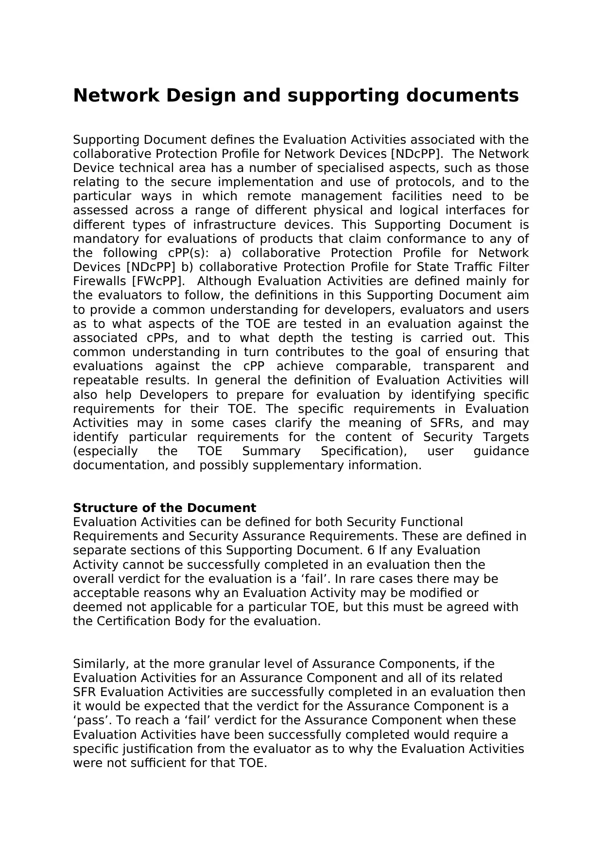
Network Design and supporting documents
Supporting Document defines the Evaluation Activities associated with the
collaborative Protection Profile for Network Devices [NDcPP]. The Network
Device technical area has a number of specialised aspects, such as those
relating to the secure implementation and use of protocols, and to the
particular ways in which remote management facilities need to be
assessed across a range of different physical and logical interfaces for
different types of infrastructure devices. This Supporting Document is
mandatory for evaluations of products that claim conformance to any of
the following cPP(s): a) collaborative Protection Profile for Network
Devices [NDcPP] b) collaborative Protection Profile for State Traffic Filter
Firewalls [FWcPP]. Although Evaluation Activities are defined mainly for
the evaluators to follow, the definitions in this Supporting Document aim
to provide a common understanding for developers, evaluators and users
as to what aspects of the TOE are tested in an evaluation against the
associated cPPs, and to what depth the testing is carried out. This
common understanding in turn contributes to the goal of ensuring that
evaluations against the cPP achieve comparable, transparent and
repeatable results. In general the definition of Evaluation Activities will
also help Developers to prepare for evaluation by identifying specific
requirements for their TOE. The specific requirements in Evaluation
Activities may in some cases clarify the meaning of SFRs, and may
identify particular requirements for the content of Security Targets
(especially the TOE Summary Specification), user guidance
documentation, and possibly supplementary information.
Structure of the Document
Evaluation Activities can be defined for both Security Functional
Requirements and Security Assurance Requirements. These are defined in
separate sections of this Supporting Document. 6 If any Evaluation
Activity cannot be successfully completed in an evaluation then the
overall verdict for the evaluation is a ‘fail’. In rare cases there may be
acceptable reasons why an Evaluation Activity may be modified or
deemed not applicable for a particular TOE, but this must be agreed with
the Certification Body for the evaluation.
Similarly, at the more granular level of Assurance Components, if the
Evaluation Activities for an Assurance Component and all of its related
SFR Evaluation Activities are successfully completed in an evaluation then
it would be expected that the verdict for the Assurance Component is a
‘pass’. To reach a ‘fail’ verdict for the Assurance Component when these
Evaluation Activities have been successfully completed would require a
specific justification from the evaluator as to why the Evaluation Activities
were not sufficient for that TOE.
⊘ This is a preview!⊘
Do you want full access?
Subscribe today to unlock all pages.
Trusted by 1+ million students worldwide
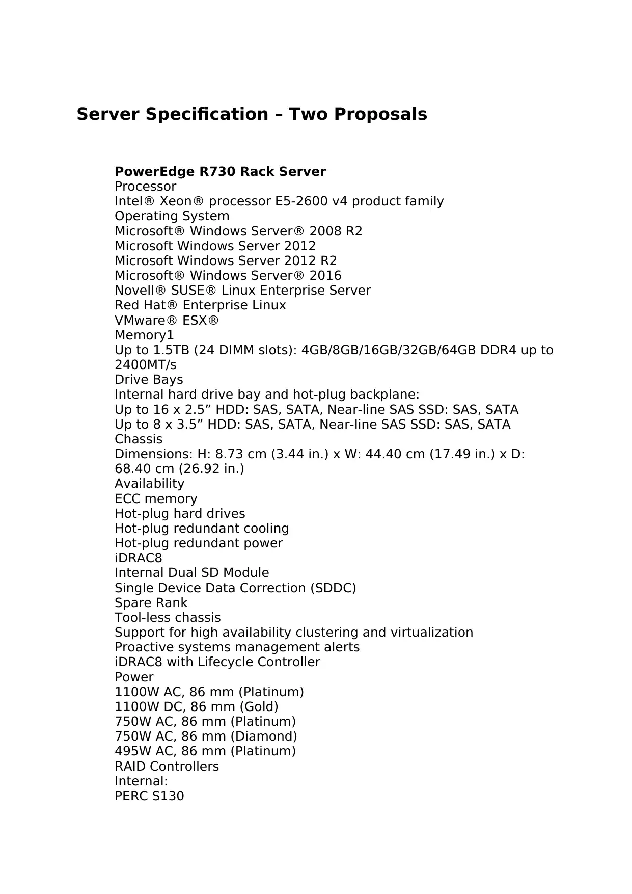
Server Specification – Two Proposals
PowerEdge R730 Rack Server
Processor
Intel® Xeon® processor E5-2600 v4 product family
Operating System
Microsoft® Windows Server® 2008 R2
Microsoft Windows Server 2012
Microsoft Windows Server 2012 R2
Microsoft® Windows Server® 2016
Novell® SUSE® Linux Enterprise Server
Red Hat® Enterprise Linux
VMware® ESX®
Memory1
Up to 1.5TB (24 DIMM slots): 4GB/8GB/16GB/32GB/64GB DDR4 up to
2400MT/s
Drive Bays
Internal hard drive bay and hot-plug backplane:
Up to 16 x 2.5” HDD: SAS, SATA, Near-line SAS SSD: SAS, SATA
Up to 8 x 3.5” HDD: SAS, SATA, Near-line SAS SSD: SAS, SATA
Chassis
Dimensions: H: 8.73 cm (3.44 in.) x W: 44.40 cm (17.49 in.) x D:
68.40 cm (26.92 in.)
Availability
ECC memory
Hot-plug hard drives
Hot-plug redundant cooling
Hot-plug redundant power
iDRAC8
Internal Dual SD Module
Single Device Data Correction (SDDC)
Spare Rank
Tool-less chassis
Support for high availability clustering and virtualization
Proactive systems management alerts
iDRAC8 with Lifecycle Controller
Power
1100W AC, 86 mm (Platinum)
1100W DC, 86 mm (Gold)
750W AC, 86 mm (Platinum)
750W AC, 86 mm (Diamond)
495W AC, 86 mm (Platinum)
RAID Controllers
Internal:
PERC S130
Paraphrase This Document
Need a fresh take? Get an instant paraphrase of this document with our AI Paraphraser
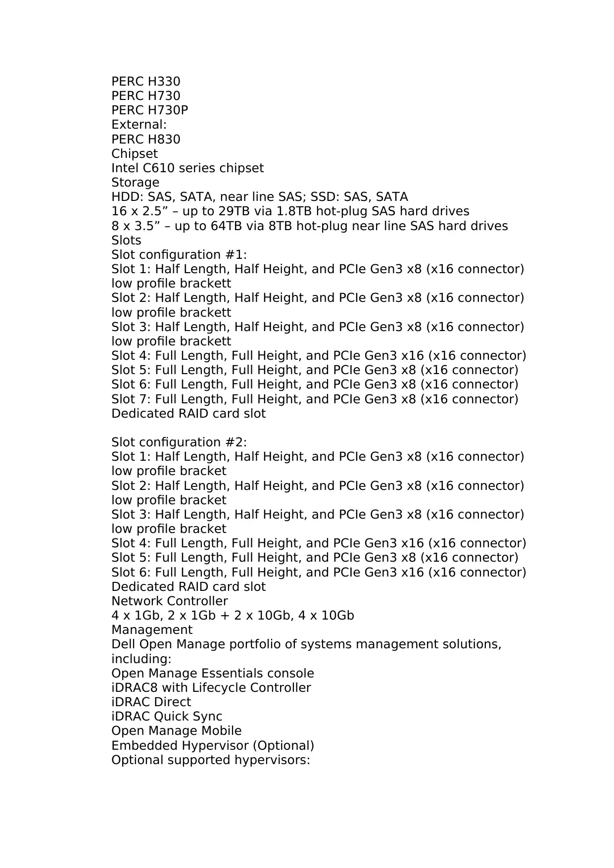
PERC H330
PERC H730
PERC H730P
External:
PERC H830
Chipset
Intel C610 series chipset
Storage
HDD: SAS, SATA, near line SAS; SSD: SAS, SATA
16 x 2.5” – up to 29TB via 1.8TB hot-plug SAS hard drives
8 x 3.5” – up to 64TB via 8TB hot-plug near line SAS hard drives
Slots
Slot configuration #1:
Slot 1: Half Length, Half Height, and PCIe Gen3 x8 (x16 connector)
low profile brackett
Slot 2: Half Length, Half Height, and PCIe Gen3 x8 (x16 connector)
low profile brackett
Slot 3: Half Length, Half Height, and PCIe Gen3 x8 (x16 connector)
low profile brackett
Slot 4: Full Length, Full Height, and PCIe Gen3 x16 (x16 connector)
Slot 5: Full Length, Full Height, and PCIe Gen3 x8 (x16 connector)
Slot 6: Full Length, Full Height, and PCIe Gen3 x8 (x16 connector)
Slot 7: Full Length, Full Height, and PCIe Gen3 x8 (x16 connector)
Dedicated RAID card slot
Slot configuration #2:
Slot 1: Half Length, Half Height, and PCIe Gen3 x8 (x16 connector)
low profile bracket
Slot 2: Half Length, Half Height, and PCIe Gen3 x8 (x16 connector)
low profile bracket
Slot 3: Half Length, Half Height, and PCIe Gen3 x8 (x16 connector)
low profile bracket
Slot 4: Full Length, Full Height, and PCIe Gen3 x16 (x16 connector)
Slot 5: Full Length, Full Height, and PCIe Gen3 x8 (x16 connector)
Slot 6: Full Length, Full Height, and PCIe Gen3 x16 (x16 connector)
Dedicated RAID card slot
Network Controller
4 x 1Gb, 2 x 1Gb + 2 x 10Gb, 4 x 10Gb
Management
Dell Open Manage portfolio of systems management solutions,
including:
Open Manage Essentials console
iDRAC8 with Lifecycle Controller
iDRAC Direct
iDRAC Quick Sync
Open Manage Mobile
Embedded Hypervisor (Optional)
Optional supported hypervisors:
Microsoft® Windows Server® 2012, with Hyper-V®
Citrix® XenServer®
VMware® vSphere® ESXiTM
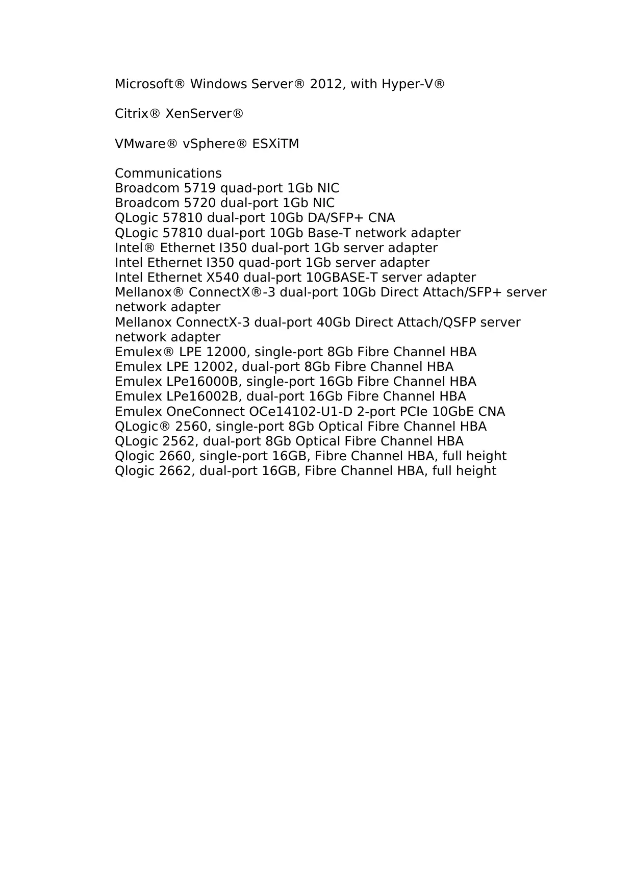
Communications
Broadcom 5719 quad-port 1Gb NIC
Broadcom 5720 dual-port 1Gb NIC
QLogic 57810 dual-port 10Gb DA/SFP+ CNA
QLogic 57810 dual-port 10Gb Base-T network adapter
Intel® Ethernet I350 dual-port 1Gb server adapter
Intel Ethernet I350 quad-port 1Gb server adapter
Intel Ethernet X540 dual-port 10GBASE-T server adapter
Mellanox® ConnectX®-3 dual-port 10Gb Direct Attach/SFP+ server
network adapter
Mellanox ConnectX-3 dual-port 40Gb Direct Attach/QSFP server
network adapter
Emulex® LPE 12000, single-port 8Gb Fibre Channel HBA
Emulex LPE 12002, dual-port 8Gb Fibre Channel HBA
Emulex LPe16000B, single-port 16Gb Fibre Channel HBA
Emulex LPe16002B, dual-port 16Gb Fibre Channel HBA
Emulex OneConnect OCe14102-U1-D 2-port PCIe 10GbE CNA
QLogic® 2560, single-port 8Gb Optical Fibre Channel HBA
QLogic 2562, dual-port 8Gb Optical Fibre Channel HBA
Qlogic 2660, single-port 16GB, Fibre Channel HBA, full height
Qlogic 2662, dual-port 16GB, Fibre Channel HBA, full height
Citrix® XenServer®
VMware® vSphere® ESXiTM
Communications
Broadcom 5719 quad-port 1Gb NIC
Broadcom 5720 dual-port 1Gb NIC
QLogic 57810 dual-port 10Gb DA/SFP+ CNA
QLogic 57810 dual-port 10Gb Base-T network adapter
Intel® Ethernet I350 dual-port 1Gb server adapter
Intel Ethernet I350 quad-port 1Gb server adapter
Intel Ethernet X540 dual-port 10GBASE-T server adapter
Mellanox® ConnectX®-3 dual-port 10Gb Direct Attach/SFP+ server
network adapter
Mellanox ConnectX-3 dual-port 40Gb Direct Attach/QSFP server
network adapter
Emulex® LPE 12000, single-port 8Gb Fibre Channel HBA
Emulex LPE 12002, dual-port 8Gb Fibre Channel HBA
Emulex LPe16000B, single-port 16Gb Fibre Channel HBA
Emulex LPe16002B, dual-port 16Gb Fibre Channel HBA
Emulex OneConnect OCe14102-U1-D 2-port PCIe 10GbE CNA
QLogic® 2560, single-port 8Gb Optical Fibre Channel HBA
QLogic 2562, dual-port 8Gb Optical Fibre Channel HBA
Qlogic 2660, single-port 16GB, Fibre Channel HBA, full height
Qlogic 2662, dual-port 16GB, Fibre Channel HBA, full height
⊘ This is a preview!⊘
Do you want full access?
Subscribe today to unlock all pages.
Trusted by 1+ million students worldwide
Paraphrase This Document
Need a fresh take? Get an instant paraphrase of this document with our AI Paraphraser
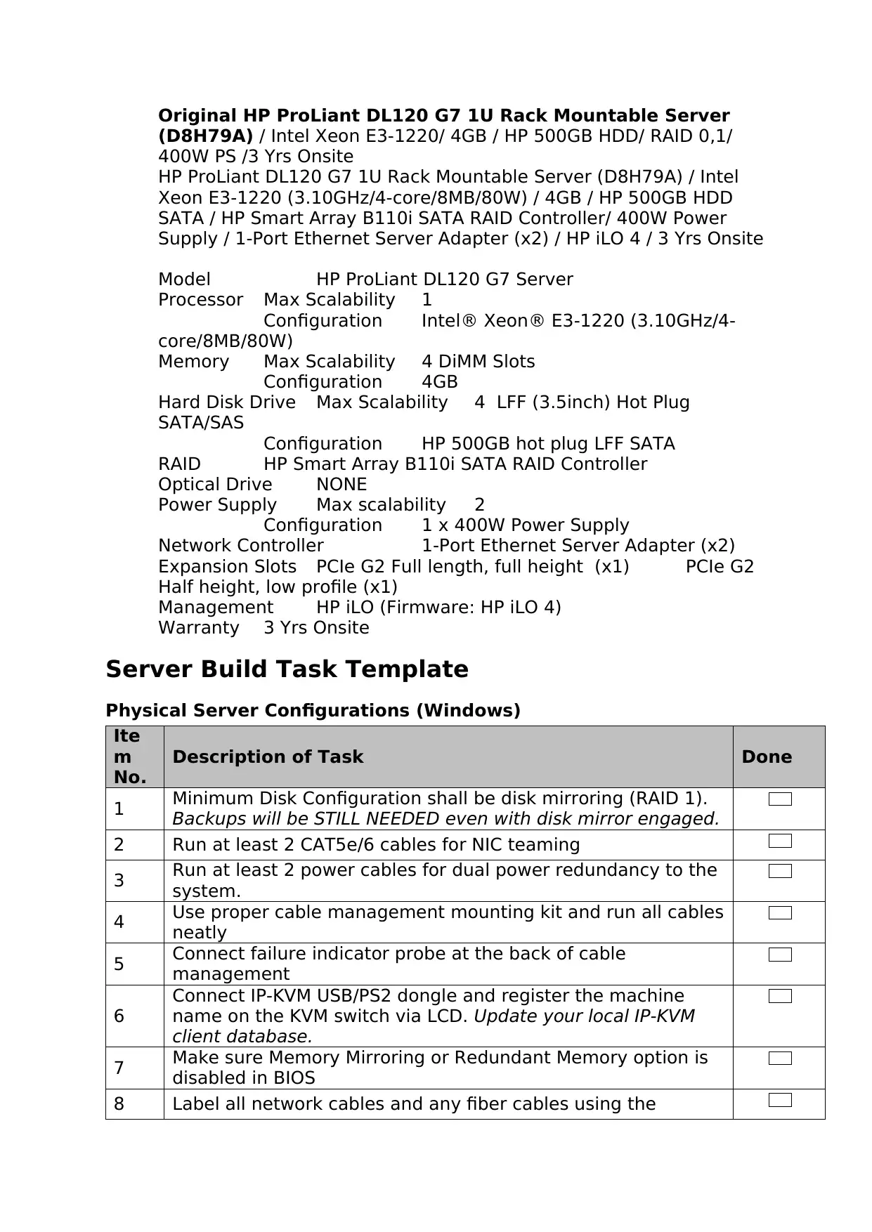
Original HP ProLiant DL120 G7 1U Rack Mountable Server
(D8H79A) / Intel Xeon E3-1220/ 4GB / HP 500GB HDD/ RAID 0,1/
400W PS /3 Yrs Onsite
HP ProLiant DL120 G7 1U Rack Mountable Server (D8H79A) / Intel
Xeon E3-1220 (3.10GHz/4-core/8MB/80W) / 4GB / HP 500GB HDD
SATA / HP Smart Array B110i SATA RAID Controller/ 400W Power
Supply / 1-Port Ethernet Server Adapter (x2) / HP iLO 4 / 3 Yrs Onsite
Model HP ProLiant DL120 G7 Server
Processor Max Scalability 1
Configuration Intel® Xeon® E3-1220 (3.10GHz/4-
core/8MB/80W)
Memory Max Scalability 4 DiMM Slots
Configuration 4GB
Hard Disk Drive Max Scalability 4 LFF (3.5inch) Hot Plug
SATA/SAS
Configuration HP 500GB hot plug LFF SATA
RAID HP Smart Array B110i SATA RAID Controller
Optical Drive NONE
Power Supply Max scalability 2
Configuration 1 x 400W Power Supply
Network Controller 1-Port Ethernet Server Adapter (x2)
Expansion Slots PCIe G2 Full length, full height (x1) PCIe G2
Half height, low profile (x1)
Management HP iLO (Firmware: HP iLO 4)
Warranty 3 Yrs Onsite
Server Build Task Template
Physical Server Configurations (Windows)
Ite
m
No.
Description of Task Done
1 Minimum Disk Configuration shall be disk mirroring (RAID 1).
Backups will be STILL NEEDED even with disk mirror engaged.
2 Run at least 2 CAT5e/6 cables for NIC teaming
3 Run at least 2 power cables for dual power redundancy to the
system.
4 Use proper cable management mounting kit and run all cables
neatly
5 Connect failure indicator probe at the back of cable
management
6
Connect IP-KVM USB/PS2 dongle and register the machine
name on the KVM switch via LCD. Update your local IP-KVM
client database.
7 Make sure Memory Mirroring or Redundant Memory option is
disabled in BIOS
8 Label all network cables and any fiber cables using the
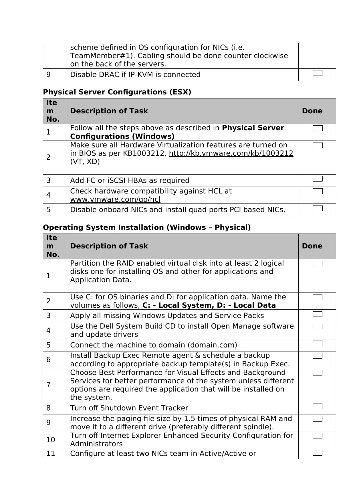
scheme defined in OS configuration for NICs (i.e.
TeamMember#1). Cabling should be done counter clockwise
on the back of the servers.
9 Disable DRAC if IP-KVM is connected
Physical Server Configurations (ESX)
Ite
m
No.
Description of Task Done
1 Follow all the steps above as described in Physical Server
Configurations (Windows)
2
Make sure all Hardware Virtualization features are turned on
in BIOS as per KB1003212, http://kb.vmware.com/kb/1003212
(VT, XD)
3 Add FC or iSCSI HBAs as required
4 Check hardware compatibility against HCL at
www.vmware.com/go/hcl
5 Disable onboard NICs and install quad ports PCI based NICs.
Operating System Installation (Windows – Physical)
Ite
m
No.
Description of Task Done
1
Partition the RAID enabled virtual disk into at least 2 logical
disks one for installing OS and other for applications and
Application Data.
2 Use C: for OS binaries and D: for application data. Name the
volumes as follows, C: - Local System, D: - Local Data
3 Apply all missing Windows Updates and Service Packs
4 Use the Dell System Build CD to install Open Manage software
and update drivers
5 Connect the machine to domain (domain.com)
6 Install Backup Exec Remote agent & schedule a backup
according to appropriate backup template(s) in Backup Exec.
7
Choose Best Performance for Visual Effects and Background
Services for better performance of the system unless different
options are required the application that will be installed on
the system.
8 Turn off Shutdown Event Tracker
9 Increase the paging file size by 1.5 times of physical RAM and
move it to a different drive (preferably different spindle).
10 Turn off Internet Explorer Enhanced Security Configuration for
Administrators
11 Configure at least two NICs team in Active/Active or
⊘ This is a preview!⊘
Do you want full access?
Subscribe today to unlock all pages.
Trusted by 1+ million students worldwide
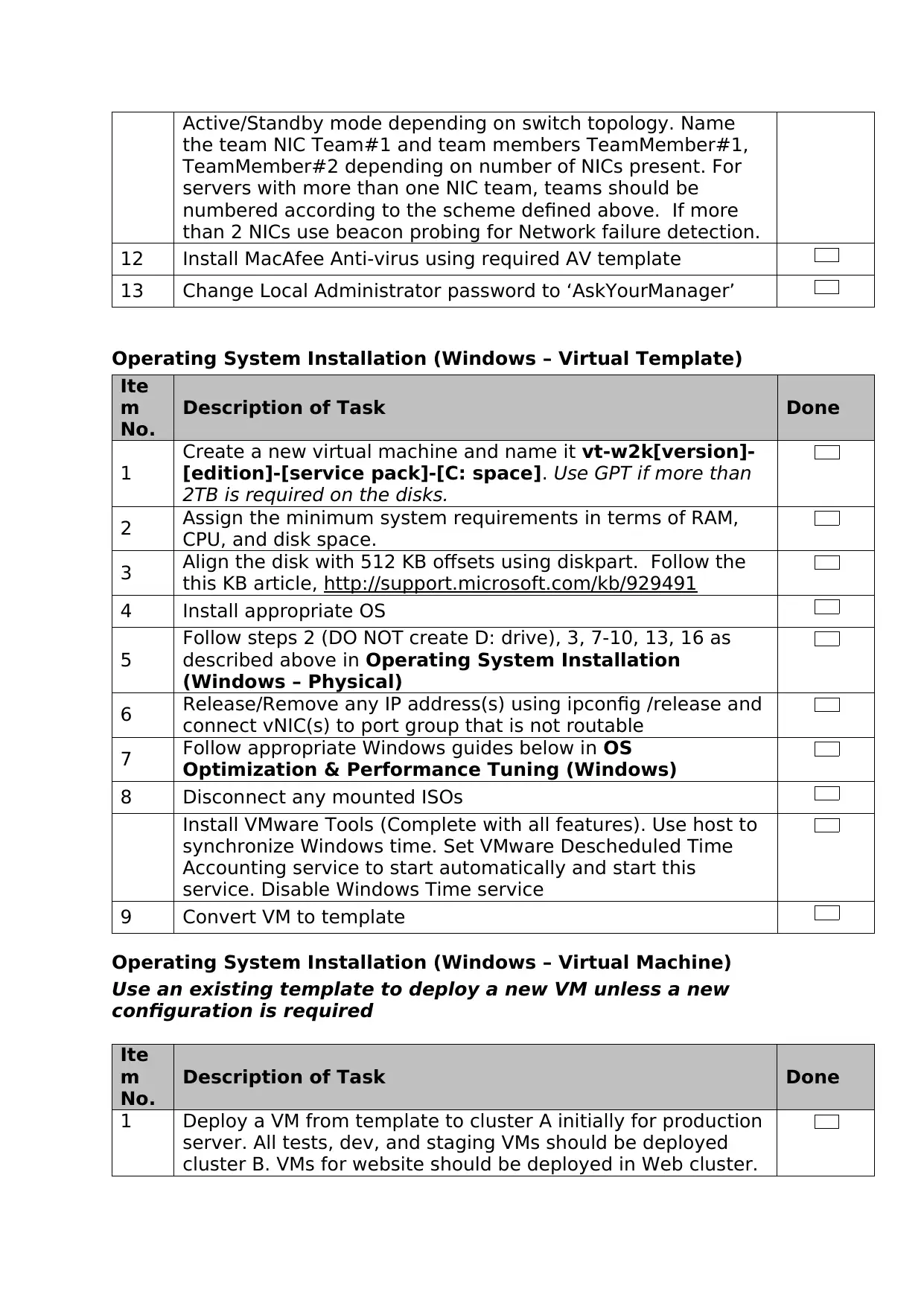
Active/Standby mode depending on switch topology. Name
the team NIC Team#1 and team members TeamMember#1,
TeamMember#2 depending on number of NICs present. For
servers with more than one NIC team, teams should be
numbered according to the scheme defined above. If more
than 2 NICs use beacon probing for Network failure detection.
12 Install MacAfee Anti-virus using required AV template
13 Change Local Administrator password to ‘AskYourManager’
Operating System Installation (Windows – Virtual Template)
Ite
m
No.
Description of Task Done
1
Create a new virtual machine and name it vt-w2k[version]-
[edition]-[service pack]-[C: space]. Use GPT if more than
2TB is required on the disks.
2 Assign the minimum system requirements in terms of RAM,
CPU, and disk space.
3 Align the disk with 512 KB offsets using diskpart. Follow the
this KB article, http://support.microsoft.com/kb/929491
4 Install appropriate OS
5
Follow steps 2 (DO NOT create D: drive), 3, 7-10, 13, 16 as
described above in Operating System Installation
(Windows – Physical)
6 Release/Remove any IP address(s) using ipconfig /release and
connect vNIC(s) to port group that is not routable
7 Follow appropriate Windows guides below in OS
Optimization & Performance Tuning (Windows)
8 Disconnect any mounted ISOs
Install VMware Tools (Complete with all features). Use host to
synchronize Windows time. Set VMware Descheduled Time
Accounting service to start automatically and start this
service. Disable Windows Time service
9 Convert VM to template
Operating System Installation (Windows – Virtual Machine)
Use an existing template to deploy a new VM unless a new
configuration is required
Ite
m
No.
Description of Task Done
1 Deploy a VM from template to cluster A initially for production
server. All tests, dev, and staging VMs should be deployed
cluster B. VMs for website should be deployed in Web cluster.
Paraphrase This Document
Need a fresh take? Get an instant paraphrase of this document with our AI Paraphraser
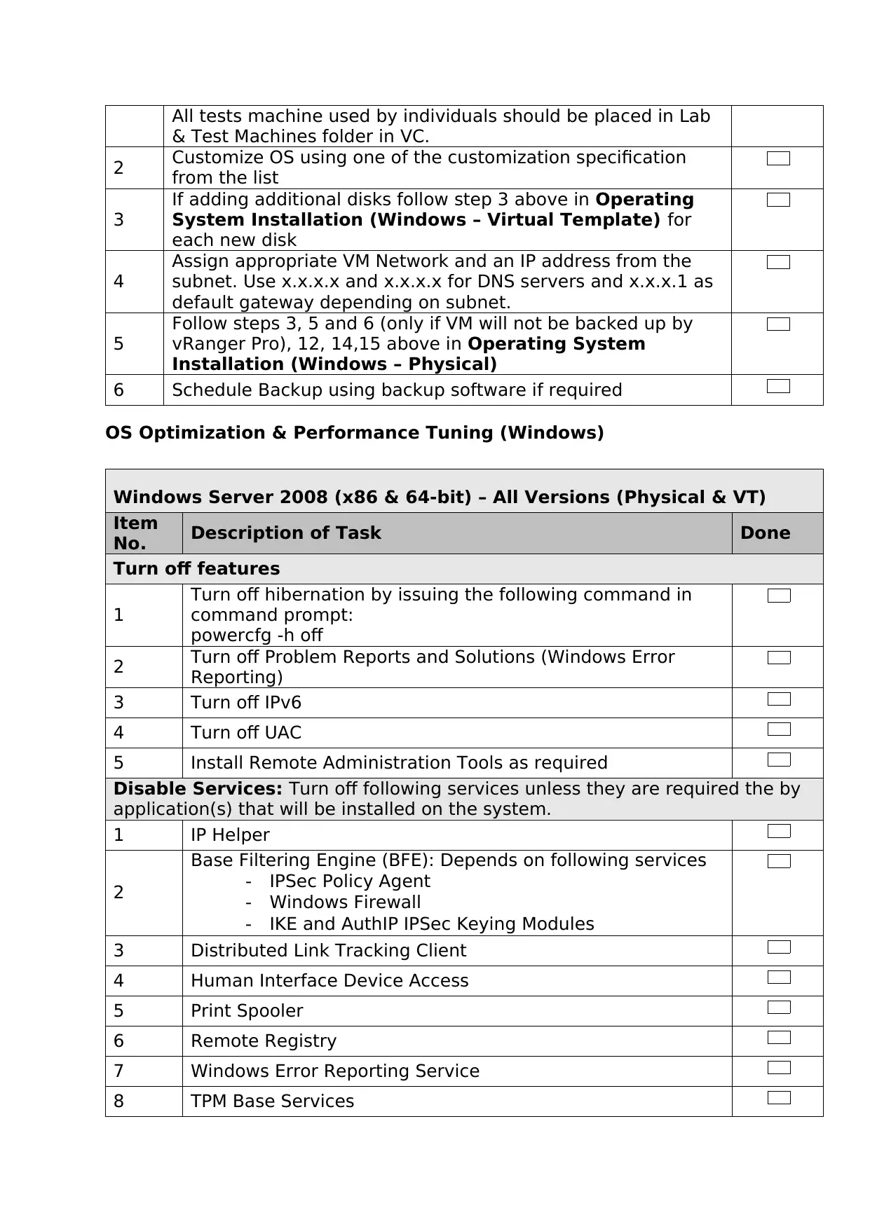
All tests machine used by individuals should be placed in Lab
& Test Machines folder in VC.
2 Customize OS using one of the customization specification
from the list
3
If adding additional disks follow step 3 above in Operating
System Installation (Windows – Virtual Template) for
each new disk
4
Assign appropriate VM Network and an IP address from the
subnet. Use x.x.x.x and x.x.x.x for DNS servers and x.x.x.1 as
default gateway depending on subnet.
5
Follow steps 3, 5 and 6 (only if VM will not be backed up by
vRanger Pro), 12, 14,15 above in Operating System
Installation (Windows – Physical)
6 Schedule Backup using backup software if required
OS Optimization & Performance Tuning (Windows)
Windows Server 2008 (x86 & 64-bit) – All Versions (Physical & VT)
Item
No. Description of Task Done
Turn off features
1
Turn off hibernation by issuing the following command in
command prompt:
powercfg -h off
2 Turn off Problem Reports and Solutions (Windows Error
Reporting)
3 Turn off IPv6
4 Turn off UAC
5 Install Remote Administration Tools as required
Disable Services: Turn off following services unless they are required the by
application(s) that will be installed on the system.
1 IP Helper
2
Base Filtering Engine (BFE): Depends on following services
- IPSec Policy Agent
- Windows Firewall
- IKE and AuthIP IPSec Keying Modules
3 Distributed Link Tracking Client
4 Human Interface Device Access
5 Print Spooler
6 Remote Registry
7 Windows Error Reporting Service
8 TPM Base Services
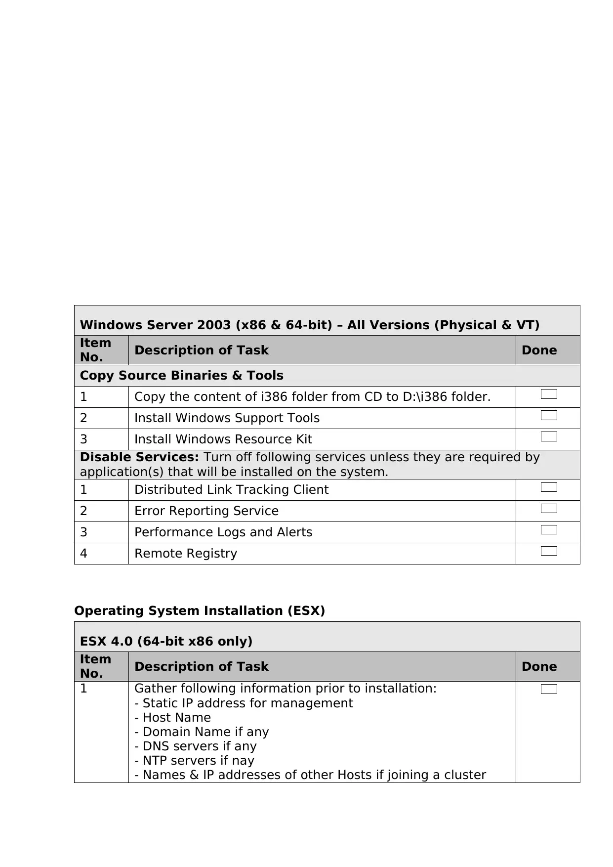
Windows Server 2003 (x86 & 64-bit) – All Versions (Physical & VT)
Item
No. Description of Task Done
Copy Source Binaries & Tools
1 Copy the content of i386 folder from CD to D:\i386 folder.
2 Install Windows Support Tools
3 Install Windows Resource Kit
Disable Services: Turn off following services unless they are required by
application(s) that will be installed on the system.
1 Distributed Link Tracking Client
2 Error Reporting Service
3 Performance Logs and Alerts
4 Remote Registry
Operating System Installation (ESX)
ESX 4.0 (64-bit x86 only)
Item
No. Description of Task Done
1 Gather following information prior to installation:
- Static IP address for management
- Host Name
- Domain Name if any
- DNS servers if any
- NTP servers if nay
- Names & IP addresses of other Hosts if joining a cluster
Item
No. Description of Task Done
Copy Source Binaries & Tools
1 Copy the content of i386 folder from CD to D:\i386 folder.
2 Install Windows Support Tools
3 Install Windows Resource Kit
Disable Services: Turn off following services unless they are required by
application(s) that will be installed on the system.
1 Distributed Link Tracking Client
2 Error Reporting Service
3 Performance Logs and Alerts
4 Remote Registry
Operating System Installation (ESX)
ESX 4.0 (64-bit x86 only)
Item
No. Description of Task Done
1 Gather following information prior to installation:
- Static IP address for management
- Host Name
- Domain Name if any
- DNS servers if any
- NTP servers if nay
- Names & IP addresses of other Hosts if joining a cluster
⊘ This is a preview!⊘
Do you want full access?
Subscribe today to unlock all pages.
Trusted by 1+ million students worldwide
1 out of 57
Related Documents


Your All-in-One AI-Powered Toolkit for Academic Success.
+13062052269
info@desklib.com
Available 24*7 on WhatsApp / Email
![[object Object]](/_next/static/media/star-bottom.7253800d.svg)
Unlock your academic potential
Copyright © 2020–2026 A2Z Services. All Rights Reserved. Developed and managed by ZUCOL.