Thermoacoustic Systems: Refrigerators, Heat Pumps & Literature Review
VerifiedAdded on 2023/06/15
|8
|1695
|463
Literature Review
AI Summary
This literature review provides an overview of thermoacoustic systems, focusing on the interaction between pressure, density, and temperature variations of acoustic waves. It discusses the thermoacoustic effect, thermoacoustic prime movers, and thermoacoustic refrigerators, highlighting the Stirling cycle within these systems. The review identifies a literature gap concerning the limited range of working fluids used in previous research, primarily Helium and nitrogen, and suggests exploring alternatives like argon, ammonia, or carbon dioxide. It classifies thermoacoustic systems into standing-wave and traveling-wave types, detailing the parameters affecting pressure frequency such as working fluid, resonator length, and temperature gradient. The review also explores the application of thermoacoustics in refrigerators and heat pumps, emphasizing their potential for environmentally friendly cooling solutions. Desklib offers additional resources including past papers and solved assignments.
Running Head: THERMOACOUSTIC SYSTEMS
Thermoacoustic Systems
Name
Institutional affiliation
Thermoacoustic Systems
Name
Institutional affiliation
Paraphrase This Document
Need a fresh take? Get an instant paraphrase of this document with our AI Paraphraser
THERMOACOUSTIC SYSTEM 2
LITERATURE REVIEW
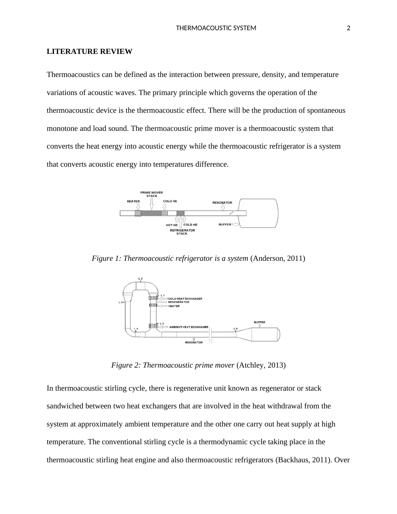
Thermoacoustics can be defined as the interaction between pressure, density, and temperature
variations of acoustic waves. The primary principle which governs the operation of the
thermoacoustic device is the thermoacoustic effect. There will be the production of spontaneous
monotone and load sound. The thermoacoustic prime mover is a thermoacoustic system that
converts the heat energy into acoustic energy while the thermoacoustic refrigerator is a system
that converts acoustic energy into temperatures difference.
Figure 1: Thermoacoustic refrigerator is a system (Anderson, 2011)
Figure 2: Thermoacoustic prime mover (Atchley, 2013)
In thermoacoustic stirling cycle, there is regenerative unit known as regenerator or stack
sandwiched between two heat exchangers that are involved in the heat withdrawal from the
system at approximately ambient temperature and the other one carry out heat supply at high
temperature. The conventional stirling cycle is a thermodynamic cycle taking place in the
thermoacoustic stirling heat engine and also thermoacoustic refrigerators (Backhaus, 2011). Over
LITERATURE REVIEW
Thermoacoustics can be defined as the interaction between pressure, density, and temperature
variations of acoustic waves. The primary principle which governs the operation of the
thermoacoustic device is the thermoacoustic effect. There will be the production of spontaneous
monotone and load sound. The thermoacoustic prime mover is a thermoacoustic system that
converts the heat energy into acoustic energy while the thermoacoustic refrigerator is a system
that converts acoustic energy into temperatures difference.
Figure 1: Thermoacoustic refrigerator is a system (Anderson, 2011)
Figure 2: Thermoacoustic prime mover (Atchley, 2013)
In thermoacoustic stirling cycle, there is regenerative unit known as regenerator or stack
sandwiched between two heat exchangers that are involved in the heat withdrawal from the
system at approximately ambient temperature and the other one carry out heat supply at high
temperature. The conventional stirling cycle is a thermodynamic cycle taking place in the
thermoacoustic stirling heat engine and also thermoacoustic refrigerators (Backhaus, 2011). Over
THERMOACOUSTIC SYSTEM 3
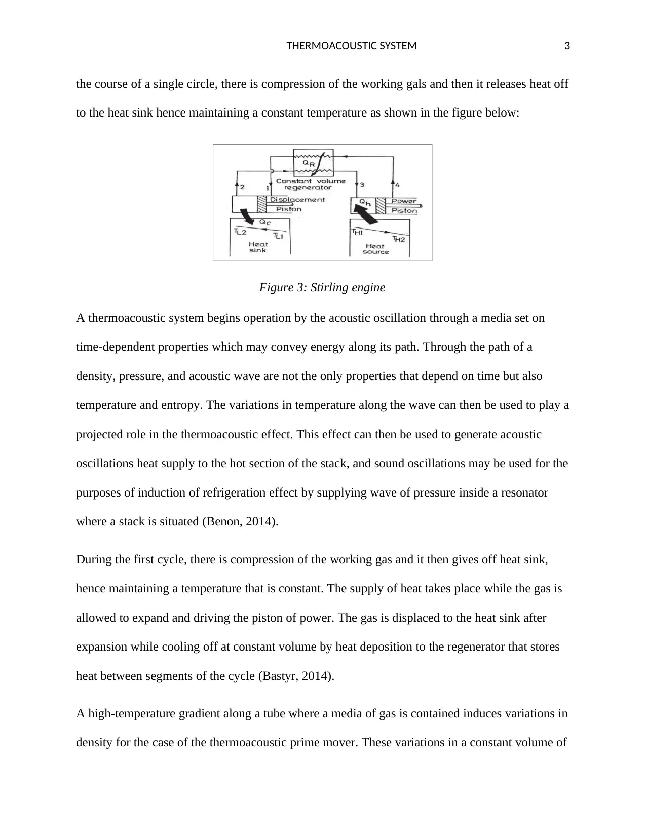
the course of a single circle, there is compression of the working gals and then it releases heat off
to the heat sink hence maintaining a constant temperature as shown in the figure below:
Figure 3: Stirling engine
A thermoacoustic system begins operation by the acoustic oscillation through a media set on
time-dependent properties which may convey energy along its path. Through the path of a
density, pressure, and acoustic wave are not the only properties that depend on time but also
temperature and entropy. The variations in temperature along the wave can then be used to play a
projected role in the thermoacoustic effect. This effect can then be used to generate acoustic
oscillations heat supply to the hot section of the stack, and sound oscillations may be used for the
purposes of induction of refrigeration effect by supplying wave of pressure inside a resonator
where a stack is situated (Benon, 2014).
During the first cycle, there is compression of the working gas and it then gives off heat sink,
hence maintaining a temperature that is constant. The supply of heat takes place while the gas is
allowed to expand and driving the piston of power. The gas is displaced to the heat sink after
expansion while cooling off at constant volume by heat deposition to the regenerator that stores
heat between segments of the cycle (Bastyr, 2014).
A high-temperature gradient along a tube where a media of gas is contained induces variations in
density for the case of the thermoacoustic prime mover. These variations in a constant volume of
⊘ This is a preview!⊘
Do you want full access?
Subscribe today to unlock all pages.
Trusted by 1+ million students worldwide
THERMOACOUSTIC SYSTEM 4
matter force variations in pressure. The thermoacoustic oscillation cycle is a combination of
pressure changes and heat transfer in a sinusoidal pattern. The oscillation that is self-induced can
be stimulated through suitable phasing of pressure changes and heat transfer (Bhatti, 2011).
Literature Gap
There are numerous previous studies that have been performed in regard to the thermoacoustic
systems which have been performed or will be performed in the near future. Some of these
studies that have been done previously regarding thermoacoustic engines include analysis of
pressure wave developed by thermoacoustic engines, dependency of TAE on temperature
gradient at the length of resonator and stack, possibility of reducing the footprint of the
refrigerators by using a coiled resonator, and the prediction of the thermoacoustic cooling effect
between stack ends (Raspet, 2016). The working fluids use in numerous research use Helium and
nitrogen which plays an important role in deciding the operating frequency and the pressure
amplitude (Versteeg, 2011). The literatures gap in these research is that they failed use other
working fluids such as argon ammonia, or carbon (iv) oxide.
Classification and pertaining parametrical review
Thermoacoustic systems can be classified into standing-wave systems or travelling-wave
systems. The parameters that make up the travelling-wave system include a loop and resonator
tube which contains a bypass loop, three heat exchangers, and a regenerator as shown in the
figure below:
Paraphrase This Document
Need a fresh take? Get an instant paraphrase of this document with our AI Paraphraser
THERMOACOUSTIC SYSTEM 5
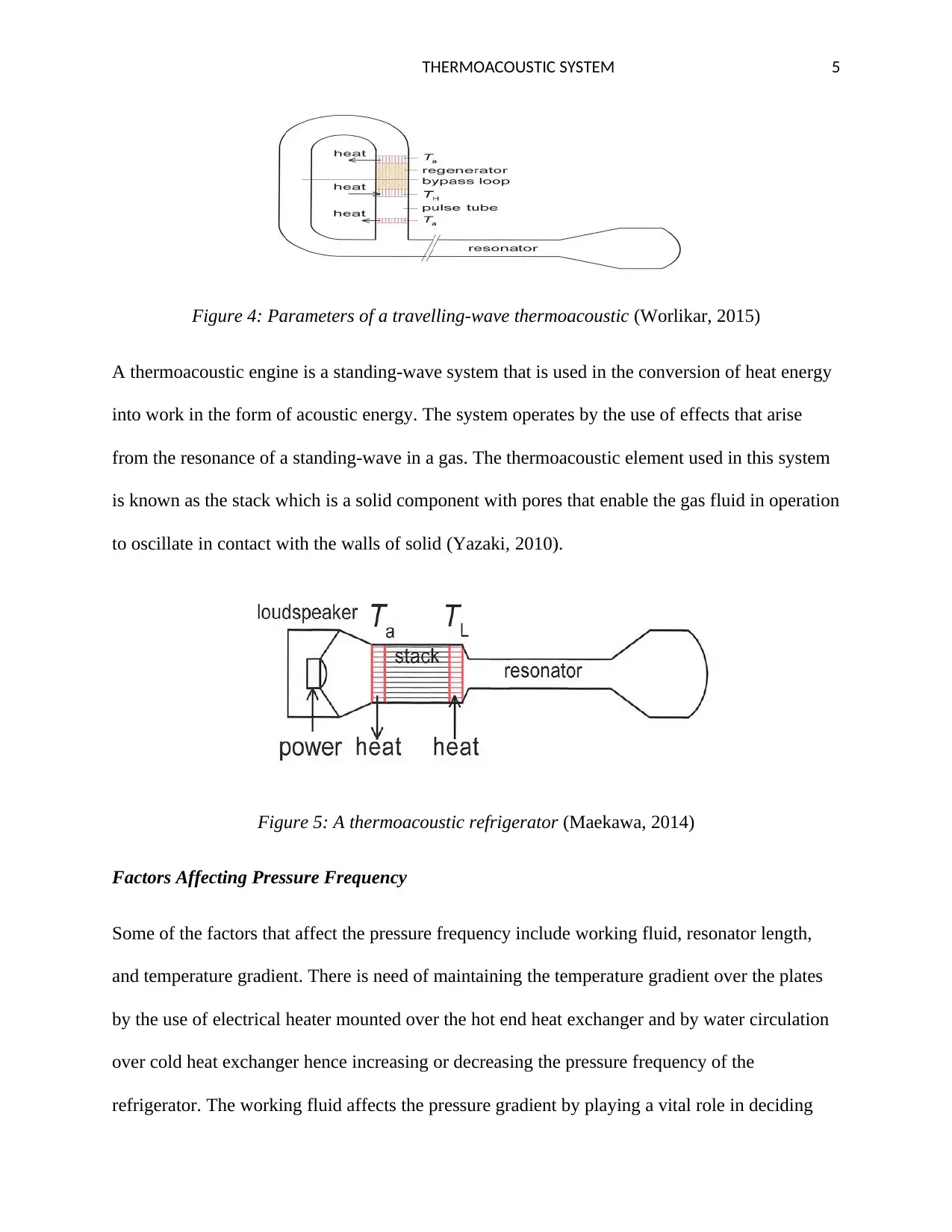
Figure 4: Parameters of a travelling-wave thermoacoustic (Worlikar, 2015)
A thermoacoustic engine is a standing-wave system that is used in the conversion of heat energy
into work in the form of acoustic energy. The system operates by the use of effects that arise
from the resonance of a standing-wave in a gas. The thermoacoustic element used in this system
is known as the stack which is a solid component with pores that enable the gas fluid in operation
to oscillate in contact with the walls of solid (Yazaki, 2010).
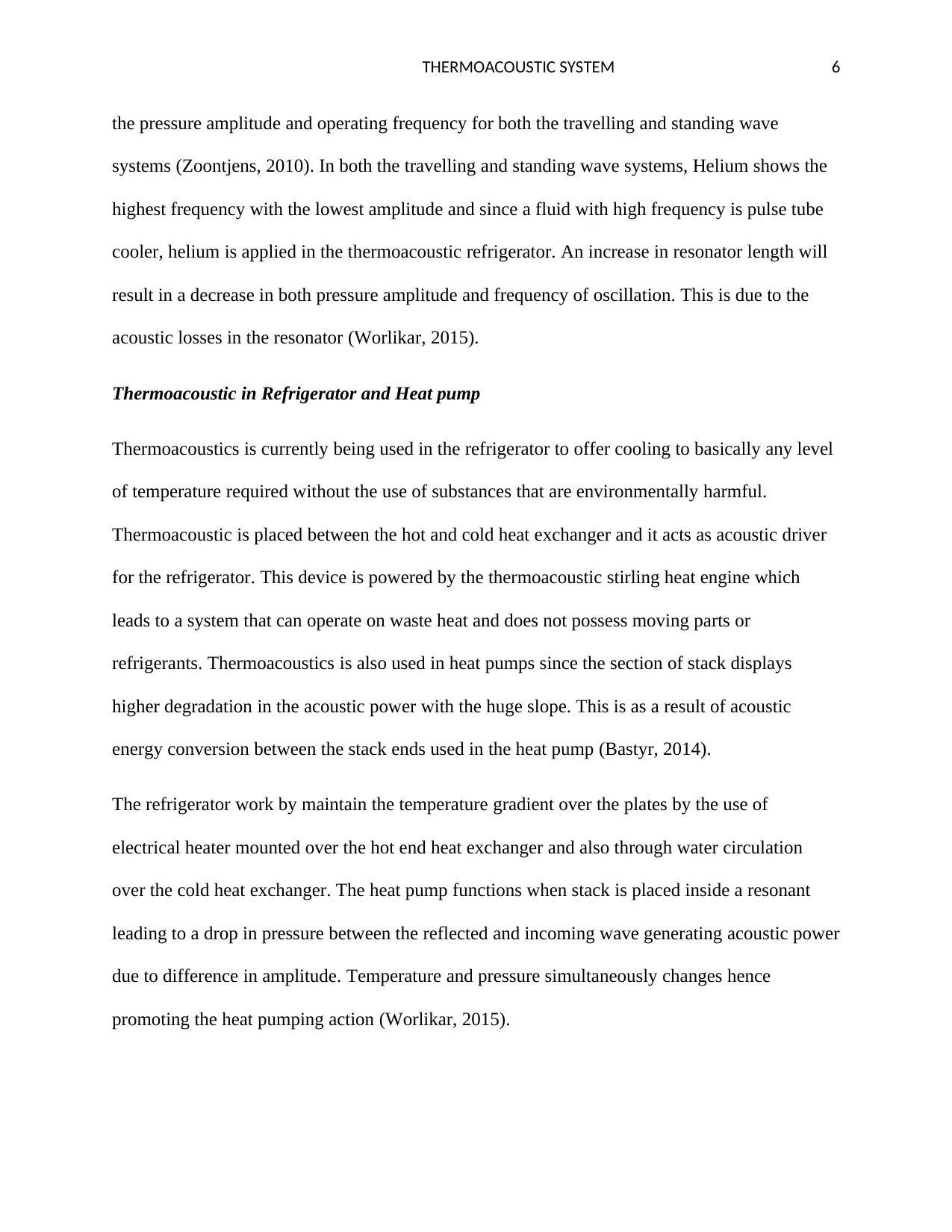
Figure 5: A thermoacoustic refrigerator (Maekawa, 2014)
Factors Affecting Pressure Frequency
Some of the factors that affect the pressure frequency include working fluid, resonator length,
and temperature gradient. There is need of maintaining the temperature gradient over the plates
by the use of electrical heater mounted over the hot end heat exchanger and by water circulation
over cold heat exchanger hence increasing or decreasing the pressure frequency of the
refrigerator. The working fluid affects the pressure gradient by playing a vital role in deciding
Figure 4: Parameters of a travelling-wave thermoacoustic (Worlikar, 2015)
A thermoacoustic engine is a standing-wave system that is used in the conversion of heat energy
into work in the form of acoustic energy. The system operates by the use of effects that arise
from the resonance of a standing-wave in a gas. The thermoacoustic element used in this system
is known as the stack which is a solid component with pores that enable the gas fluid in operation
to oscillate in contact with the walls of solid (Yazaki, 2010).
Figure 5: A thermoacoustic refrigerator (Maekawa, 2014)
Factors Affecting Pressure Frequency
Some of the factors that affect the pressure frequency include working fluid, resonator length,
and temperature gradient. There is need of maintaining the temperature gradient over the plates
by the use of electrical heater mounted over the hot end heat exchanger and by water circulation
over cold heat exchanger hence increasing or decreasing the pressure frequency of the
refrigerator. The working fluid affects the pressure gradient by playing a vital role in deciding
THERMOACOUSTIC SYSTEM 6
the pressure amplitude and operating frequency for both the travelling and standing wave
systems (Zoontjens, 2010). In both the travelling and standing wave systems, Helium shows the
highest frequency with the lowest amplitude and since a fluid with high frequency is pulse tube
cooler, helium is applied in the thermoacoustic refrigerator. An increase in resonator length will
result in a decrease in both pressure amplitude and frequency of oscillation. This is due to the
acoustic losses in the resonator (Worlikar, 2015).
Thermoacoustic in Refrigerator and Heat pump
Thermoacoustics is currently being used in the refrigerator to offer cooling to basically any level
of temperature required without the use of substances that are environmentally harmful.
Thermoacoustic is placed between the hot and cold heat exchanger and it acts as acoustic driver
for the refrigerator. This device is powered by the thermoacoustic stirling heat engine which
leads to a system that can operate on waste heat and does not possess moving parts or
refrigerants. Thermoacoustics is also used in heat pumps since the section of stack displays
higher degradation in the acoustic power with the huge slope. This is as a result of acoustic
energy conversion between the stack ends used in the heat pump (Bastyr, 2014).
The refrigerator work by maintain the temperature gradient over the plates by the use of
electrical heater mounted over the hot end heat exchanger and also through water circulation
over the cold heat exchanger. The heat pump functions when stack is placed inside a resonant
leading to a drop in pressure between the reflected and incoming wave generating acoustic power
due to difference in amplitude. Temperature and pressure simultaneously changes hence
promoting the heat pumping action (Worlikar, 2015).
⊘ This is a preview!⊘
Do you want full access?
Subscribe today to unlock all pages.
Trusted by 1+ million students worldwide
THERMOACOUSTIC SYSTEM 7
References
Anderson, O. (2011). Refrigeration in America. Washington: JKennikat Press.
Atchley, A. (2013). Stability curves for a thermoacoustic prime mover. New York: J. Acoust. Soc.
Backhaus, S. (2011). A thermoacoustic stirling heat engine. Paris: Journal of the Acoustical Society of
America.
Bastyr, K. (2014). High-frequency thermoacoustic-stirling heat engine demonstration device. Melbourne:
Acoustics Research Letters Online.
Benon, B. (2014). Numerical Simulation of Stack-Heat Exchangers Coupling in a Thermoacoustic
Refrigerator. Michigan: AIAA.
Bhatti, M. (2011). Enhancement of r-134a automotive air conditioning system. Moscow: SAE
International Congress and Exposition.
Herman, C. (2016). Cool sound: The future of refrigeration? thermodynamic and heat transfer issues in
thermoacoustic refrigeration. Paris: Heat and Mass Transfer.
Maekawa, T. (2014). Travelling wave thermoacoustic engine in a looped tube. Colorado: Phys. Rev. Lett.
Nijeholt, M. (2010). A simple method to determine the frequency of engine-included thermoacoustic
systems. Michigan: Society of America Publications.
Raspet, R. (2016). Working gases in thermoacoustic engines. Toledo: J. Acoust. Soc. Am.
Swift, G. (2011). Thermoacoustic engines and refrigerators. London: Acoust. Soc.
Swift, G. (2013). Thermoacoustic heat transportation and energy transformation. Perth: Cryogenics.
Tominaga, A. (2013). A pistonless Stirling cooler. Perth: J. Acoust. Soc. Am.
Versteeg, W. (2011). An Introduction to Computational Fluid Dynamics. The Finite Volume Method.
Newcastle: Longman Group Ltd.
Vipperman, J. (2014). CFD simulation of a thermoacoustic engine with the coiled resonator. California:
International Communications in Heat and Mass Transfer.
Wheatley, G. (2017). Acoustic cooling engine. New York: US Patent No. 4.
Worlikar, S. (2015). Thermoacoustic Engines. Berlin: IEEE.
Yazaki, T. (2010). Thermodynamical mode selection rule observed in thermoacoustic oscillations.
Michigan: Europhys.
Zink, F. (2012). CFD simulation of thermoacoustic cooling. Chicago: International Journal of Heat and
Mass Transfer.
Zoontjens, L. (2010). Numerical Study of Flow and Energy Fields in Thermoacoustic Couples of Non-Zero
Thickness. Colorado: Int. J. Therm. Sci.,
Paraphrase This Document
Need a fresh take? Get an instant paraphrase of this document with our AI Paraphraser

THERMOACOUSTIC SYSTEM 8
1 out of 8
Your All-in-One AI-Powered Toolkit for Academic Success.
+13062052269
info@desklib.com
Available 24*7 on WhatsApp / Email
![[object Object]](/_next/static/media/star-bottom.7253800d.svg)
Unlock your academic potential
Copyright © 2020–2025 A2Z Services. All Rights Reserved. Developed and managed by ZUCOL.