Analysis of Refrigeration System Thermodynamics and Performance
VerifiedAdded on 2021/12/14
|5
|437
|166
Report
AI Summary
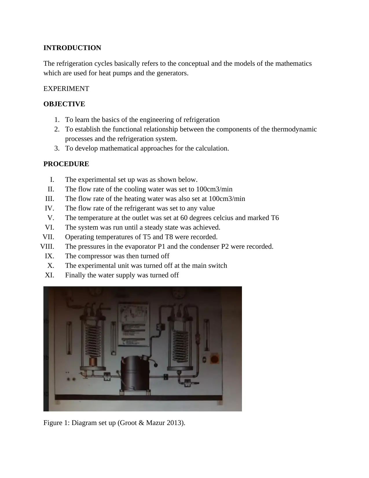
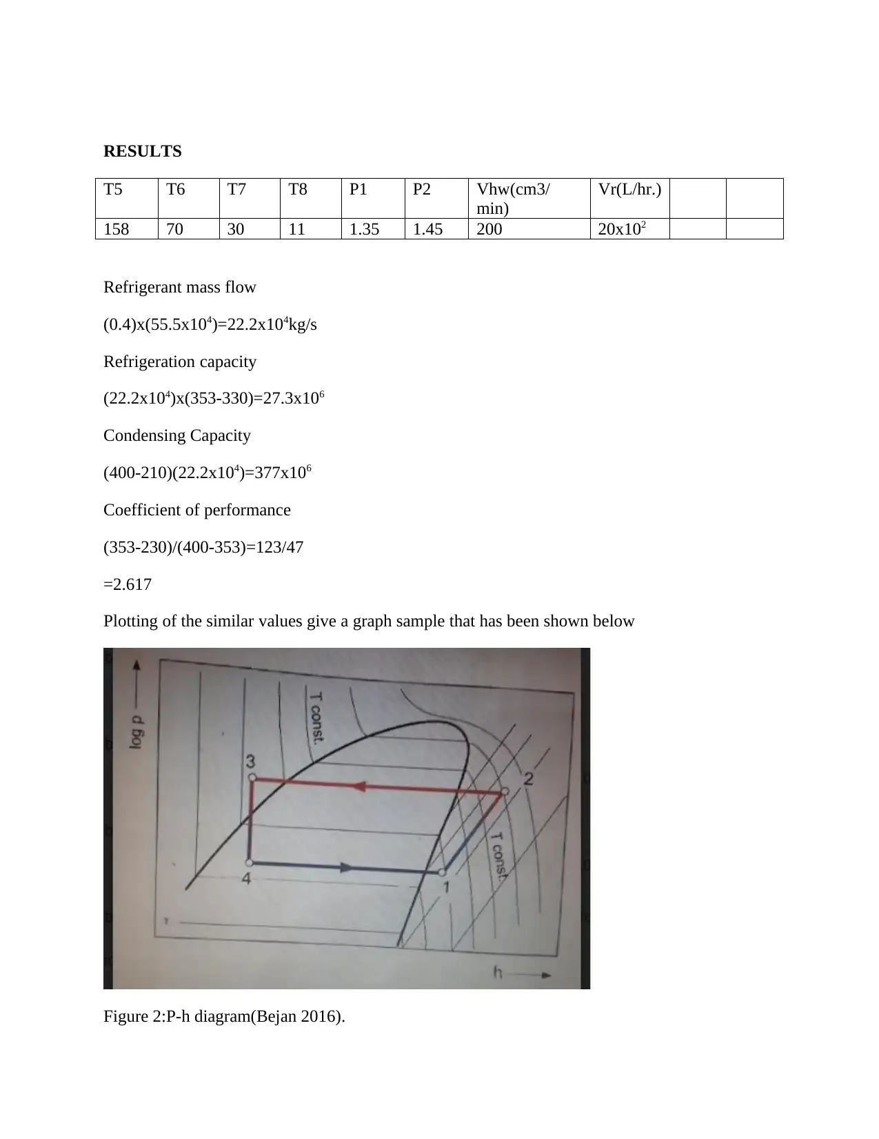
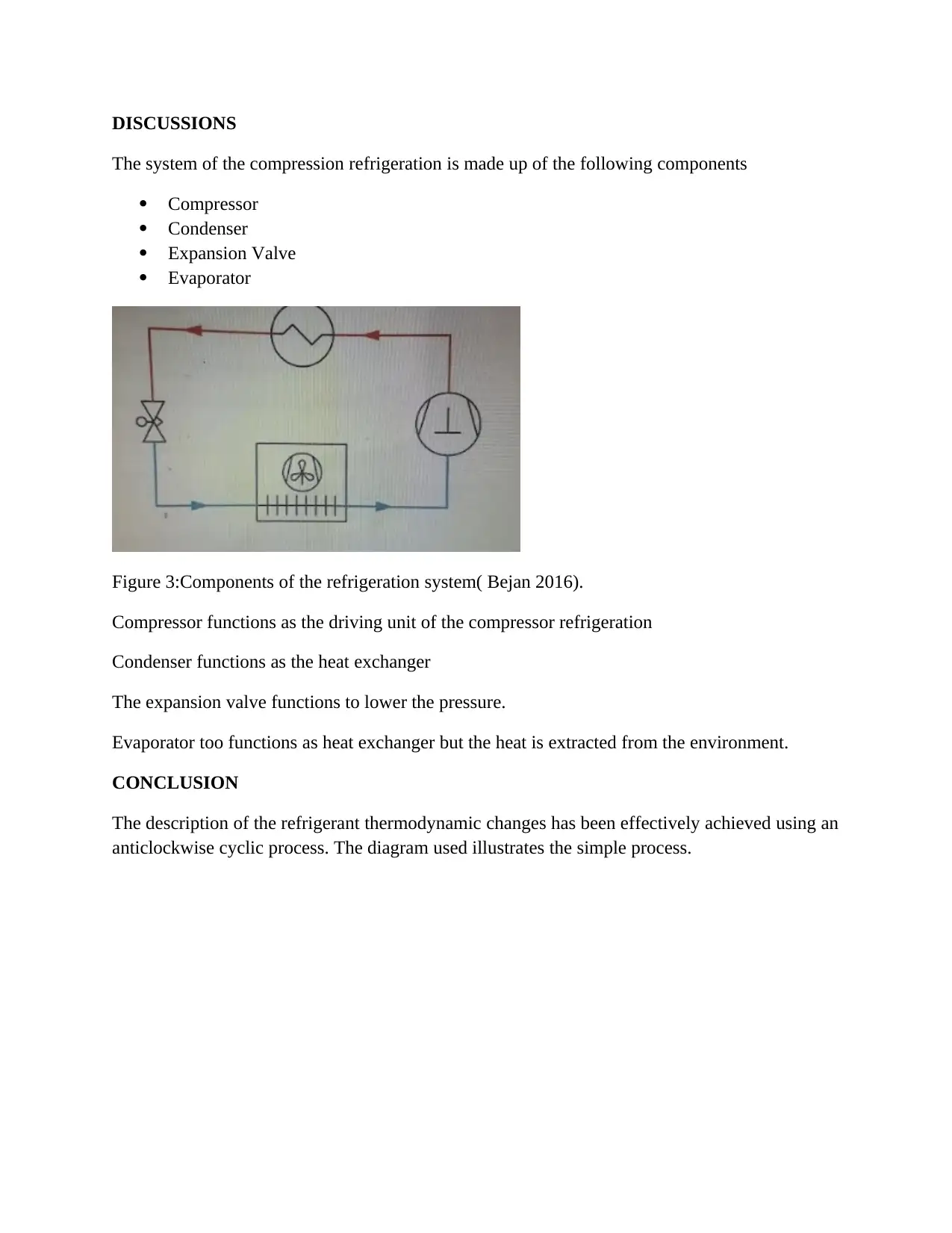
This report presents a comprehensive analysis of a refrigeration system's thermodynamics, focusing on the fundamental principles and operational characteristics. The study details the system's components, including the compressor, condenser, expansion valve, and evaporator, and their respective functions. The report outlines the experimental setup, including the flow rates of cooling and heating water, and the recorded temperatures and pressures. The data collected is used to calculate key performance indicators such as the refrigeration capacity and the coefficient of performance (COP). Furthermore, the report illustrates the thermodynamic processes using a P-h diagram and discusses the cyclic nature of the refrigeration process. The analysis concludes with a summary of the refrigerant's thermodynamic changes and the effectiveness of the system's design and operation.

1 out of 5
Your All-in-One AI-Powered Toolkit for Academic Success.
+13062052269
info@desklib.com
Available 24*7 on WhatsApp / Email
![[object Object]](/_next/static/media/star-bottom.7253800d.svg)
Copyright © 2020–2026 A2Z Services. All Rights Reserved. Developed and managed by ZUCOL.