University Aerofoil Lift Experiment Report: ENG 590 Thermodynamics
VerifiedAdded on 2022/08/14
|22
|2263
|18
Report
AI Summary
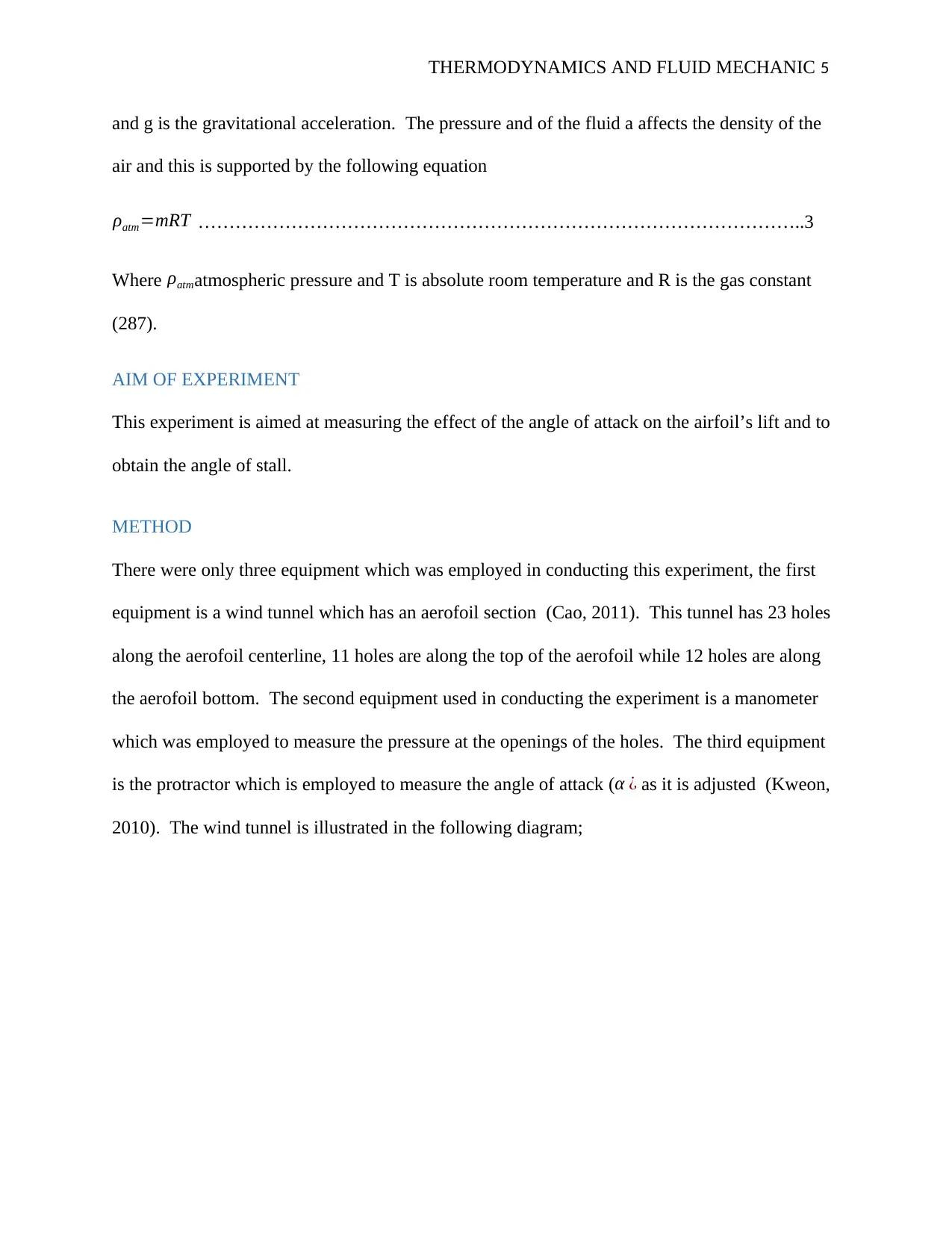
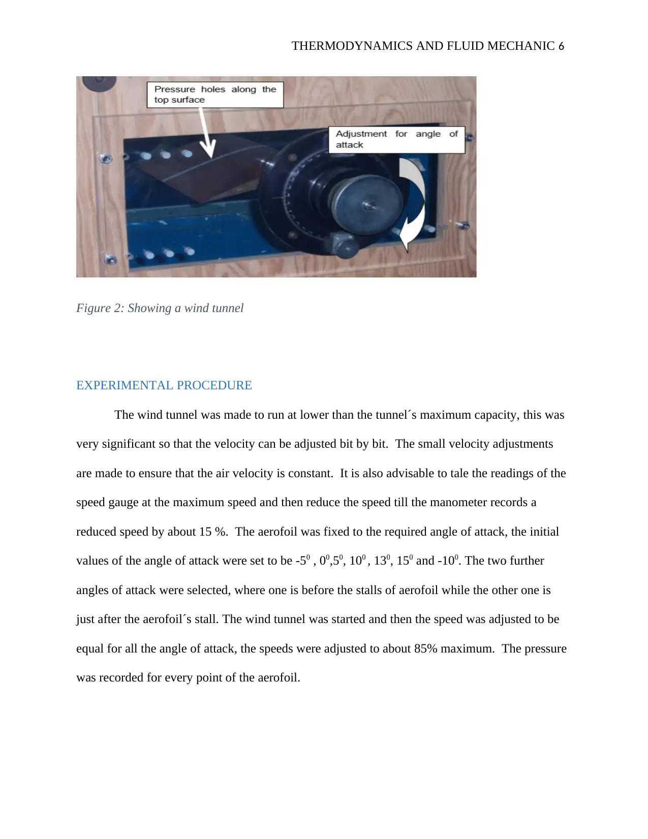
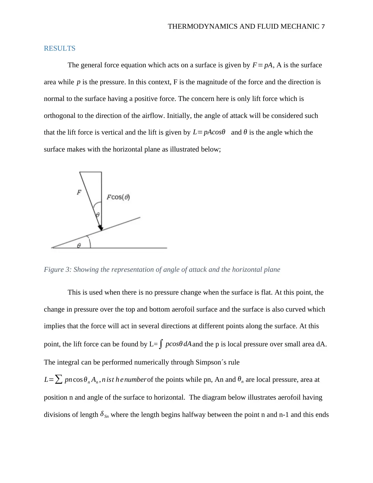
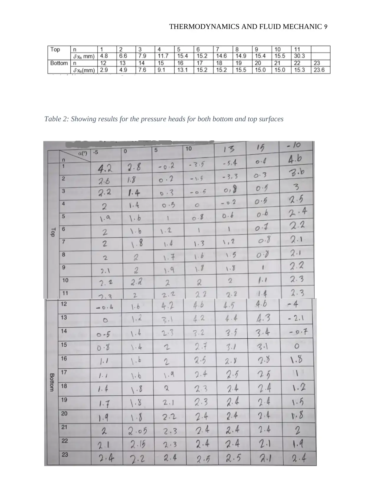
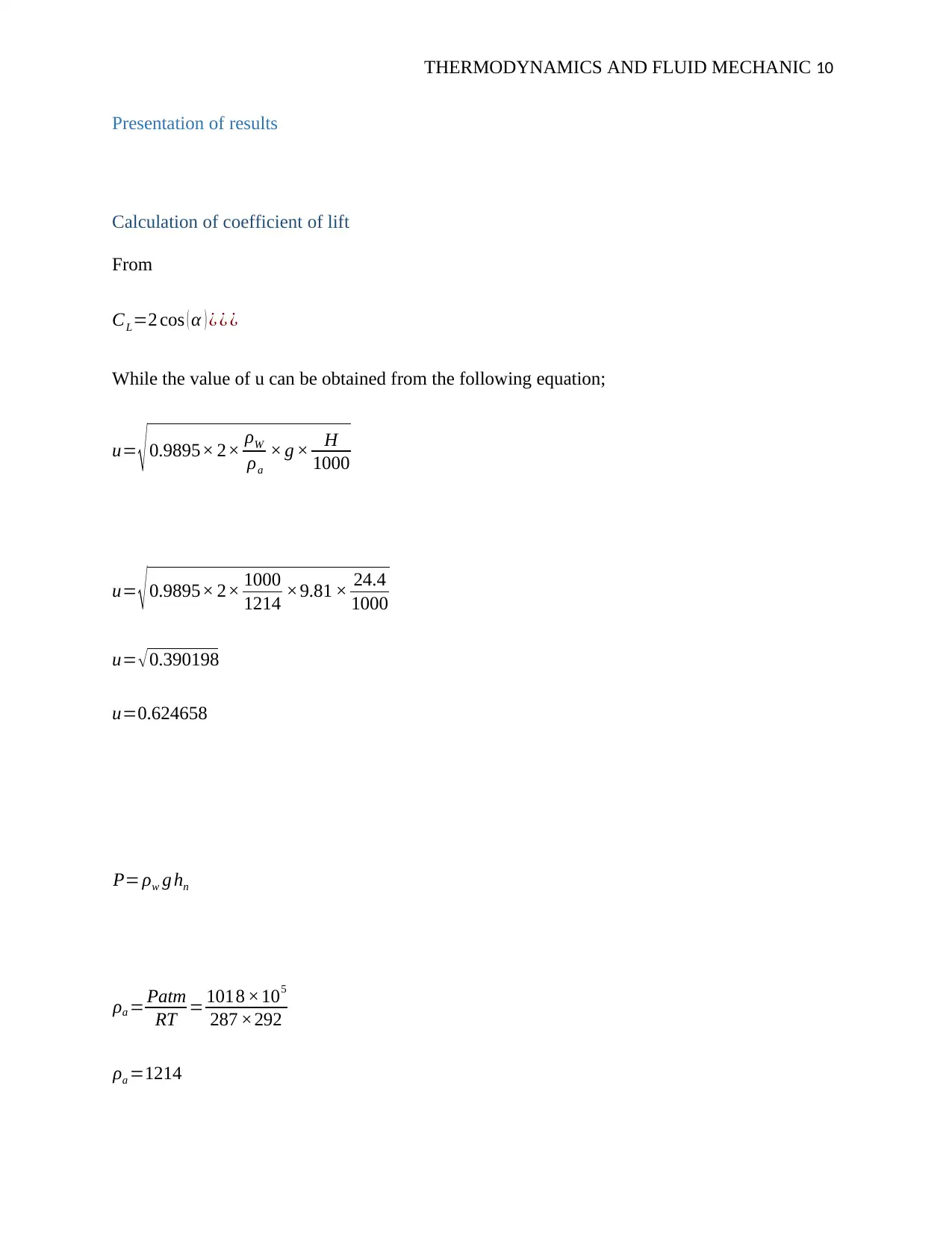
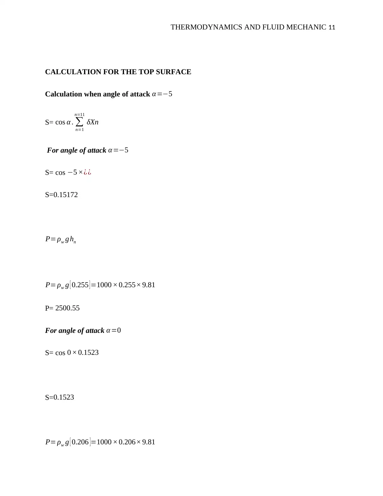
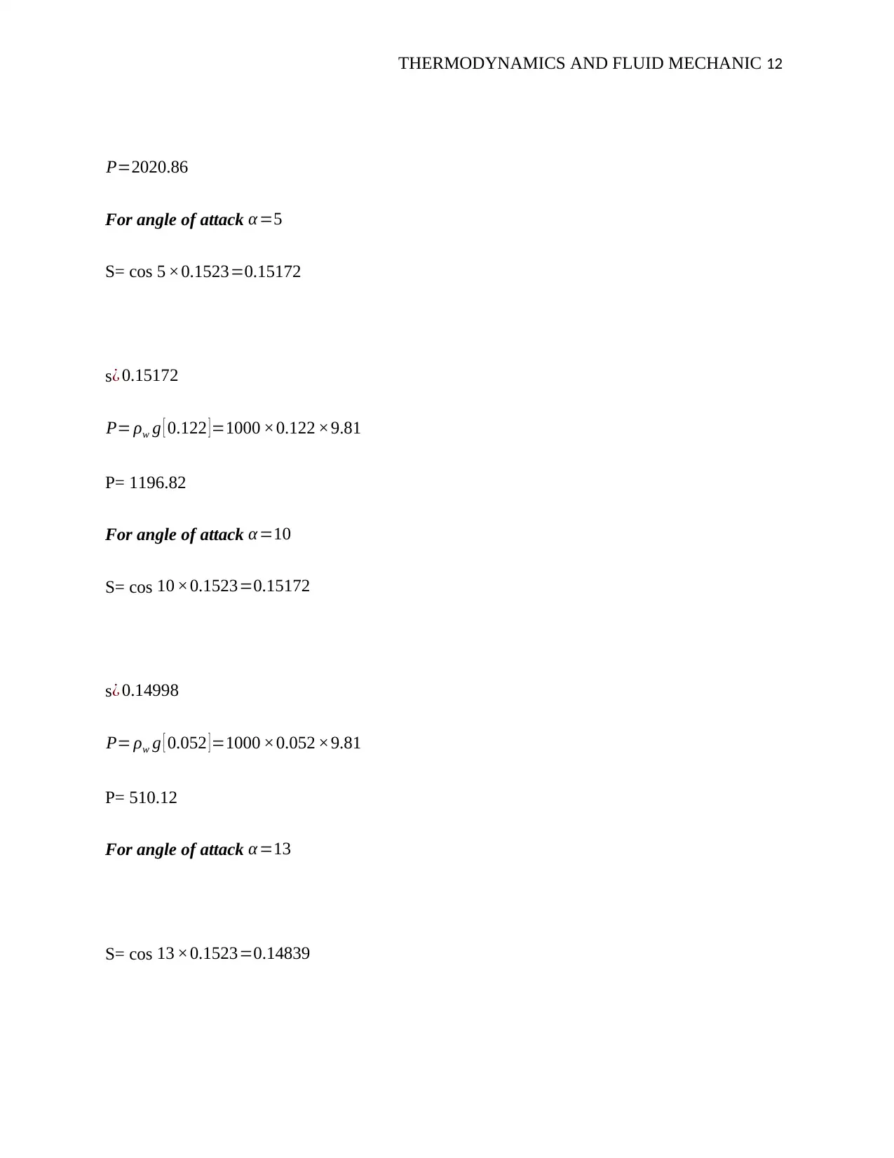
This report details an experiment conducted to investigate the lift characteristics of an aerofoil. The study aimed to measure the effect of the angle of attack on the aerofoil's lift and determine the stall angle. The experiment utilized a wind tunnel, manometer, and protractor to measure pressure and angle variations. The report presents experimental procedures, results, and calculations, including the coefficient of lift at various angles of attack. Graphical representations show the relationship between the angle of attack and the coefficient of lift, as well as pressure changes across the aerofoil. The discussion section analyzes these results in relation to established aerodynamic principles, such as Bernoulli's principle, and identifies potential sources of error. The conclusion summarizes the findings, emphasizing the correlation between the angle of attack and the coefficient of lift, and how the experimental results align with the theory. The report also includes a bibliography of relevant sources.

THERMODYNAMICS AND FLUID MECHANIC 1
THERMODYNAMICS AND FLUID MECHANICS
By Name
Course
Instructor
Institution
Location
Date
THERMODYNAMICS AND FLUID MECHANICS
By Name
Course
Instructor
Institution
Location
Date
Paraphrase This Document
Need a fresh take? Get an instant paraphrase of this document with our AI Paraphraser

THERMODYNAMICS AND FLUID MECHANIC 2
TABLE OF CONTENT
TABLE OF CONTENT...............................................................................................................................2
TITLE..........................................................................................................................................................3
INTRODUCTION.......................................................................................................................................3
AIM OF EXPERIMENT.........................................................................................................................5
METHOD....................................................................................................................................................5
EXPERIMENTAL PROCEDURE..........................................................................................................6
RESULTS...................................................................................................................................................7
Presentation of results............................................................................................................................10
Calculation of coefficient of lift.........................................................................................................10
Discussion.................................................................................................................................................20
Conclusion.................................................................................................................................................21
Bibliography..............................................................................................................................................22

THERMODYNAMICS AND FLUID MECHANIC 3
TITLE: LIFT ON AN AEROFOIL
INTRODUCTION
In case a body or a particle is put in a flow, the particle will experience some forces from
its environment fluid (liquid or gas). This force exerted in the same direction of the flow of the
fluid is referred to as a drag. While there is another force that is orthogonal to the direction of the
fluid flow is referred to as downforce or a lift. The lift and the drag forces are generated from the
two effects which are viscosity skin friction and difference in pressure acting of the particle or
the body in a fluid. For the Airfoils which have a streamlined body, the flow will remain attached
over the surfaces of the body. This implies that drag is obtained from skin friction while the lift
is from a difference of pressure between the lower and upper surfaces of the body.
In a bluff object like a chimney or a car, the layer boundary is isolated at the same point
which forms a turbulent wake hence drag force dominates. The airfoil’s lift determined by the
angle between the direction of fluid flow and the angle between the airfoil, this angle is better
referred to as the angle of attack (Weber, 2010). When the angle of attack increases from zero to
maximum it will result in increase of lift also from zero to maximum (critical angle of attack) of
which the lift will abruptly decrease. This critical angle of attack (maximum lift) is referred to as
a stall. The drag, lift and angle of attack in aerofoil is illustrated in the following diagram;
⊘ This is a preview!⊘
Do you want full access?
Subscribe today to unlock all pages.

Trusted by 1+ million students worldwide

THERMODYNAMICS AND FLUID MECHANIC 4
Figure 1: Showing drag, lift, and angle of attack in aerofoil (Tang, 2010).
From figure 1 above it is possible to relate the drag and the lift to the kinetic of flow ½ ρ μ2 that
has a unit of pressure. Through defining the coefficient of drag and lift CD and CL respectively
such that
L=CL A ρ μ2
2 ……………………………………………………………….........................1
Where A is a measure of the area of the body in fluid, L is the lift force, ρ is the fluid density and
μ the velocity of the fluid.
If the fluid is air then velocity is obtained from the Bernoulli's equation as below;
u= √ 0.9895× 2× ρw
ρa × g × H
1000 …………………………………………………..2
Where
u isthe velocity of air , ρa isthe air density , ρw id the water density , H is the difference ∈ pressure
Paraphrase This Document
Need a fresh take? Get an instant paraphrase of this document with our AI Paraphraser

THERMODYNAMICS AND FLUID MECHANIC 5
and g is the gravitational acceleration. The pressure and of the fluid a affects the density of the
air and this is supported by the following equation
ρatm=mRT ……………………………………………………………………………………..3
Where ρatmatmospheric pressure and T is absolute room temperature and R is the gas constant
(287).
AIM OF EXPERIMENT
This experiment is aimed at measuring the effect of the angle of attack on the airfoil’s lift and to
obtain the angle of stall.
METHOD
There were only three equipment which was employed in conducting this experiment, the first
equipment is a wind tunnel which has an aerofoil section (Cao, 2011). This tunnel has 23 holes
along the aerofoil centerline, 11 holes are along the top of the aerofoil while 12 holes are along
the aerofoil bottom. The second equipment used in conducting the experiment is a manometer
which was employed to measure the pressure at the openings of the holes. The third equipment
is the protractor which is employed to measure the angle of attack (α ¿ as it is adjusted (Kweon,
2010). The wind tunnel is illustrated in the following diagram;

THERMODYNAMICS AND FLUID MECHANIC 6
Figure 2: Showing a wind tunnel
EXPERIMENTAL PROCEDURE
The wind tunnel was made to run at lower than the tunnel´s maximum capacity, this was
very significant so that the velocity can be adjusted bit by bit. The small velocity adjustments
are made to ensure that the air velocity is constant. It is also advisable to tale the readings of the
speed gauge at the maximum speed and then reduce the speed till the manometer records a
reduced speed by about 15 %. The aerofoil was fixed to the required angle of attack, the initial
values of the angle of attack were set to be -50 , 00,50, 100 , 130, 150 and -100. The two further
angles of attack were selected, where one is before the stalls of aerofoil while the other one is
just after the aerofoil´s stall. The wind tunnel was started and then the speed was adjusted to be
equal for all the angle of attack, the speeds were adjusted to about 85% maximum. The pressure
was recorded for every point of the aerofoil.
⊘ This is a preview!⊘
Do you want full access?
Subscribe today to unlock all pages.

Trusted by 1+ million students worldwide

THERMODYNAMICS AND FLUID MECHANIC 7
RESULTS
The general force equation which acts on a surface is given by F= pA, A is the surface
area while p is the pressure. In this context, F is the magnitude of the force and the direction is
normal to the surface having a positive force. The concern here is only lift force which is
orthogonal to the direction of the airflow. Initially, the angle of attack will be considered such
that the lift force is vertical and the lift is given by L= pAcosθ and θ is the angle which the
surface makes with the horizontal plane as illustrated below;
Figure 3: Showing the representation of angle of attack and the horizontal plane
This is used when there is no pressure change when the surface is flat. At this point, the
change in pressure over the top and bottom aerofoil surface and the surface is also curved which
implies that the force will act in several directions at different points along the surface. At this
point, the lift force can be found by L=∫ pcosθ dAand the p is local pressure over small area dA.
The integral can be performed numerically through Simpson´s rule
L=∑ pn cos θn An , n ist h e numberof the points while pn, An and θn are local pressure, area at
position n and angle of the surface to horizontal. The diagram below illustrates aerofoil having
divisions of length δ Sn where the length begins halfway between the point n and n-1 and this ends
Paraphrase This Document
Need a fresh take? Get an instant paraphrase of this document with our AI Paraphraser

THERMODYNAMICS AND FLUID MECHANIC 8
at halfway between point n and n+a . When the width of the aerofoil is w, and the area An can be
illustrated as An =wδ Sn= wδxn
cos θ ∧δXn ist h e h orizontal projections for
δ Sn. This is illustrated as below;
Figure 4: Showing the movement of air across the top surface of the aerofoil
The total lift can be expressed as below;
L=w cos(α) ( ∑
n=12
n=23
px δX n−∑
1
11
pn δX n ) and the coefficient of the lift is given by the following
equation
CL= 2 L
wsρu2
Width w cancels out and it is not required to find obtain the coefficient. The aerofoil length s1
can be obtained in a good approximation as ¿ ∑
n =1
n=11
δ X n . T h e values of δ X n
have been measured∧given∈the following table;
Table 1: Showing The values of δX_(n )

THERMODYNAMICS AND FLUID MECHANIC 9
Table 2: Showing results for the pressure heads for both bottom and top surfaces
⊘ This is a preview!⊘
Do you want full access?
Subscribe today to unlock all pages.

Trusted by 1+ million students worldwide

THERMODYNAMICS AND FLUID MECHANIC 10
Presentation of results
Calculation of coefficient of lift
From
CL=2 cos ( α ) ¿ ¿ ¿
While the value of u can be obtained from the following equation;
u= √0.9895× 2× ρW
ρa
× g × H
1000
u= √0.9895× 2× 1000
1214 ×9.81 × 24.4
1000
u= √0.390198
u=0.624658
P= ρw g hn
ρa = Patm
RT = 1018 ×105
287 ×292
ρa =1214
Paraphrase This Document
Need a fresh take? Get an instant paraphrase of this document with our AI Paraphraser

THERMODYNAMICS AND FLUID MECHANIC 11
CALCULATION FOR THE TOP SURFACE
Calculation when angle of attack α=−5
S= cos α . ∑
n=1
n=11
δXn
For angle of attack α =−5
S= cos −5 ׿ ¿
S=0.15172
P= ρw g hn
P= ρw g [ 0.255 ]=1000 × 0.255× 9.81
P= 2500.55
For angle of attack α =0
S= cos 0 × 0.1523
S=0.1523
P= ρw g [ 0.206 ]=1000 × 0.206× 9.81
CALCULATION FOR THE TOP SURFACE
Calculation when angle of attack α=−5
S= cos α . ∑
n=1
n=11
δXn
For angle of attack α =−5
S= cos −5 ׿ ¿
S=0.15172
P= ρw g hn
P= ρw g [ 0.255 ]=1000 × 0.255× 9.81
P= 2500.55
For angle of attack α =0
S= cos 0 × 0.1523
S=0.1523
P= ρw g [ 0.206 ]=1000 × 0.206× 9.81

THERMODYNAMICS AND FLUID MECHANIC 12
P=2020.86
For angle of attack α =5
S= cos 5 ×0.1523=0.15172
s¿ 0.15172
P= ρw g [ 0.122 ] =1000 ×0.122 ×9.81
P= 1196.82
For angle of attack α=10
S= cos 10 ×0.1523=0.15172
s¿ 0.14998
P= ρw g [ 0.052 ]=1000 ×0.052 ×9.81
P= 510.12
For angle of attack α=13
S= cos 13 ×0.1523=0.14839
P=2020.86
For angle of attack α =5
S= cos 5 ×0.1523=0.15172
s¿ 0.15172
P= ρw g [ 0.122 ] =1000 ×0.122 ×9.81
P= 1196.82
For angle of attack α=10
S= cos 10 ×0.1523=0.15172
s¿ 0.14998
P= ρw g [ 0.052 ]=1000 ×0.052 ×9.81
P= 510.12
For angle of attack α=13
S= cos 13 ×0.1523=0.14839
⊘ This is a preview!⊘
Do you want full access?
Subscribe today to unlock all pages.

Trusted by 1+ million students worldwide
1 out of 22
Related Documents

Your All-in-One AI-Powered Toolkit for Academic Success.
+13062052269
info@desklib.com
Available 24*7 on WhatsApp / Email
Unlock your academic potential
Copyright © 2020–2025 A2Z Services. All Rights Reserved. Developed and managed by ZUCOL.