Thermodynamics: System Analysis, Processes, Heat Transfer, and Engines
VerifiedAdded on 2023/06/05
|16
|2887
|340
Report
AI Summary
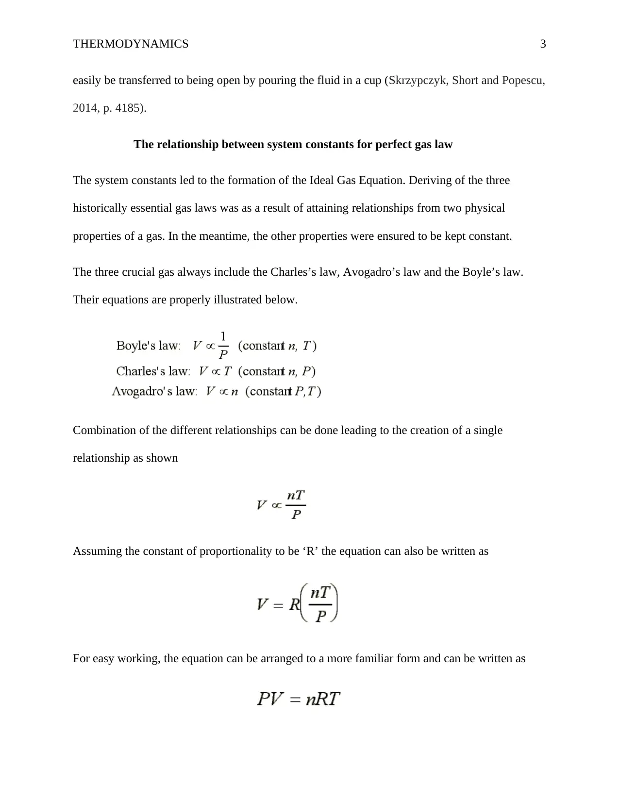
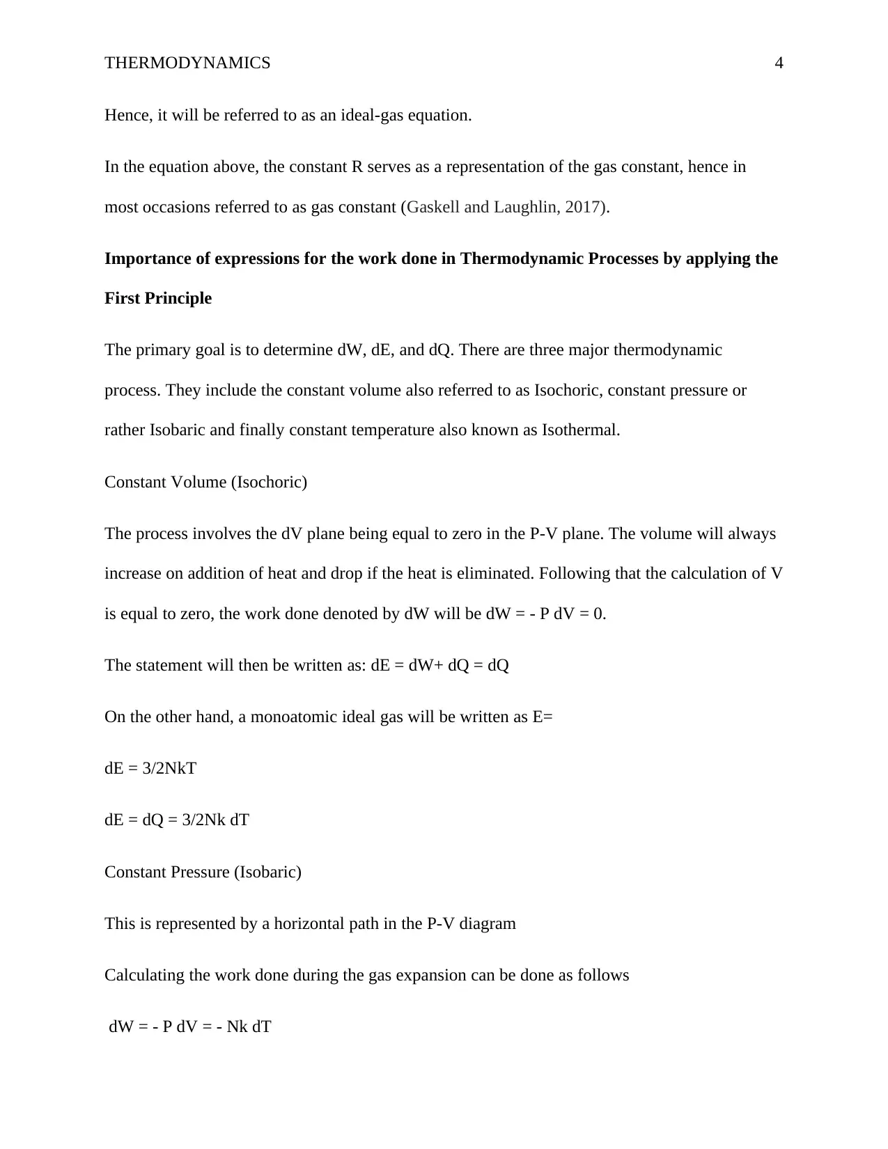
This report provides a comprehensive analysis of thermodynamics, covering various systems (open, closed, and isolated) and their properties. It explains the relationship between system constants and the ideal gas law, detailing Charles’s law, Avogadro’s law, and Boyle’s law. The report also examines the importance of expressions for work done in thermodynamic processes, applying the First Principle to constant volume (Isochoric), constant pressure (Isobaric), and constant temperature (Isothermal) processes. Furthermore, it calculates the polytropic index using the non-flow energy equation and explores the specific steady flow energy equation based on assumptions related to plant equipment. The report also details heat transfer through composite walls and heat exchangers, accounting for fouling factors, and explores heat losses through lagged and unlagged pipes, differentiating between parallel and counter flow recuperator heat exchangers. Finally, it outlines the operational sequence of four-stroke spark ignition and four-stroke compression ignition engines, explaining each stroke and their functions.

THERMODYNAMICS 1
Title
Author’s name
Institutional affiliation
Title
Author’s name
Institutional affiliation
Paraphrase This Document
Need a fresh take? Get an instant paraphrase of this document with our AI Paraphraser

THERMODYNAMICS 2
Thermodynamics
Thermodynamics is organized in different systems. The three main types of the system include
the closed system, the isolated system and open system. The transfer of masses vary in the
different systems. The transfer of the same in the open system is across its boundary. An engine
is one of the relevant examples of an open system. With the engine, there is the provision of fuel
to the engine. As a result of this, power is given out hence, the exchange of mass as well as
energy becomes complete. Apart from that, there is the emission of heat from the system that is
exchanged with the surrounding. The application of the same is also seen with boiling water
making use of an open vessel. The case involves the transfer of heat in addition to the steam
taking place in two areas, the vessel and the surrounding. A closed system, on the other hand,
involves its boundary experiencing a transfer of energy with the surrounding. However, there is
zero transfer of mass. It can be also be referred to as a fixed mass system. The application of a
closed system is seeing with a fluid for example gas or air, being compressed in the piston and
cylinder arrangement. The heating of water in a closed vessel also forms one of the appropriate
applications. In such a case study there will be the heating of the water. However, the mass
changes remain to be zero through the heating system. In addition to the open and closed system,
there is too an isolated system. The boundary of such a system experiences zero transfers across
it. If one is to carry out a study of the boundary, they will realize no transfer of mass nor energy.
An insulated piston-cylinder arrangement undergoing full compression of fluids such as air or
gas will end up being grouped under the isolated systems. In such a system the transfer of mass
and energy is reduced to nil. The thermos flask mainly used in facilitating the storage of hot
water, coffee or tea, also forms a perfect example of a closed system. However, the system can

THERMODYNAMICS 3
easily be transferred to being open by pouring the fluid in a cup (Skrzypczyk, Short and Popescu,
2014, p. 4185).
The relationship between system constants for perfect gas law
The system constants led to the formation of the Ideal Gas Equation. Deriving of the three
historically essential gas laws was as a result of attaining relationships from two physical
properties of a gas. In the meantime, the other properties were ensured to be kept constant.
The three crucial gas always include the Charles’s law, Avogadro’s law and the Boyle’s law.
Their equations are properly illustrated below.
Combination of the different relationships can be done leading to the creation of a single
relationship as shown
Assuming the constant of proportionality to be ‘R’ the equation can also be written as
For easy working, the equation can be arranged to a more familiar form and can be written as
⊘ This is a preview!⊘
Do you want full access?
Subscribe today to unlock all pages.

Trusted by 1+ million students worldwide

THERMODYNAMICS 4
Hence, it will be referred to as an ideal-gas equation.
In the equation above, the constant R serves as a representation of the gas constant, hence in
most occasions referred to as gas constant (Gaskell and Laughlin, 2017).
Importance of expressions for the work done in Thermodynamic Processes by applying the
First Principle
The primary goal is to determine dW, dE, and dQ. There are three major thermodynamic
process. They include the constant volume also referred to as Isochoric, constant pressure or
rather Isobaric and finally constant temperature also known as Isothermal.
Constant Volume (Isochoric)
The process involves the dV plane being equal to zero in the P-V plane. The volume will always
increase on addition of heat and drop if the heat is eliminated. Following that the calculation of V
is equal to zero, the work done denoted by dW will be dW = - P dV = 0.
The statement will then be written as: dE = dW+ dQ = dQ
On the other hand, a monoatomic ideal gas will be written as E=
dE = 3/2NkT
dE = dQ = 3/2Nk dT
Constant Pressure (Isobaric)
This is represented by a horizontal path in the P-V diagram
Calculating the work done during the gas expansion can be done as follows
dW = - P dV = - Nk dT
Paraphrase This Document
Need a fresh take? Get an instant paraphrase of this document with our AI Paraphraser

THERMODYNAMICS 5
On the other hand, the result of the first law is:
dQ = dE – dW = 3/2Nk dT + Nk dT = 5/2 Nk dT
Constant Temperature (Isothermal)
An isothermal path in the P-V diagram primarily facilitates its presentation hence, it attaining the
name a hyperbolic isotherm.
At the const temperature, calculating the ideal gas will be:
P = NkT/V
The work done on the gas could be calculated as follows
W= -∫vivfP dV= - NkT∫vivf = 1/V Dv
W= - NkT ln(Vf/Vi) =- Pi Vi ln(Vf/Vi)= - Pf Vf ln(Vf/Vi)
The first law results in the production of dQ + dW = dE = 0
dQ = -dW
Task 2
Calculating the polytropic index describing parameters using non-flow energy equation
The sum of the work done and the added heat results to a total change in energy.
By changing the system there will be the attaining of the reversible work done which can be
attained by

THERMODYNAMICS 6
In the equation, p serves as a representative of the pressure. V will be the volume, and the
enthalpy represented by
Can be obtained by properly applying the equation below
There are processes that are both reversible and adiabatic, such that there is no change in heat
transfers. Such processes that are generally adiabatic are referred to as isentropic. The processes
lead to two major observations being attained.
On attaining the major observations, one can now easily compute a great deal regarding the
isentropic processes concerning the ideal gases. In the case of any transformation of an ideal gas,
one will be right to tell that
and that
By making use of the general results obtained in the calculation above regarding dU and dH,
therefore,
Writing a heat capacity ratio for an ideal gas will be done as shown below
Specific Steady flow energy equation based on the assumptions on the Plant Equipment
⊘ This is a preview!⊘
Do you want full access?
Subscribe today to unlock all pages.

Trusted by 1+ million students worldwide

THERMODYNAMICS 7
The units being Joules/ second
or
There will be need to neglect the chemical and the potential energy to attain the equation below
In the equation, c serves as a representation of the speed of the fluid. The square if C divided by
two represents the kinetic energy of the fluid per unit mass which is relative to some coordinate
systems. Dividing through by mass flow will result to
Basing on that the steady flow energy equation will then be attained
Or rather
Task 3
Determine the heat transfer through the composite walls
The determination of the heat transfer through the composite walls can be done as follows
Paraphrase This Document
Need a fresh take? Get an instant paraphrase of this document with our AI Paraphraser

THERMODYNAMICS 8
Each layer will have a transfer pf heat as indicated above. The consequent solutions for layers 1
and 2 will be given by
Layer 1
Layer 2
Apply heat transfer formula to heat exchangers
The working of a heat exchanger may end up experiencing some deficiencies citing some fouling
factors. New heat exchangers are known to experience zero fouling factors. However, as the heat
exchangers are continually used, the fouling factors get to develop. The operating temperature is
one of the factors that affect the fouling factors. Hence, a heat transfer formula is needed to
facilitate the process of accounting the effects of fouling factors. The accounting is done not only
on the inner section of the tube but also the outside part.
Explore heat losses through lagged and unlagged pipes
Calculating the heat losses in a lagged pipe can be obtained by application of the equation below

THERMODYNAMICS 9
On the other hand, application of heat loss in an unlagged pipe can be obtained by carrying out a
proper addition of the radiation losses and the convective losses as shown below
Q loss=Q convection losses+ Q radiation losses
= (α∗A∗ΔT) + ϵ∗A∗σ∗ ((Tpipe) 4− (Tair)4) (with T in K]
Distinguish the difference between parallel and counter flow recuperator heat exchangers
With a counterflow heat exchanger, the low path on one end of the heat exchanger experiences a
hot fluid getting in, the other end experiencing the entering of a cold fluid. The process is known
by many citing the efficiencies associated with it. On the other hand, the Parallel Flow Heat
Exchanger serves as the operating principle when it comes to the double pipe heat exchanger.
The heat exchanger basically involves all fluids entering at one point and all coming out from the
other end. The temperature difference is always large at the entrance point, a case not
experienced at the exit point, hence differing from counter flow heat exchanger.
Task 4
The operational sequence of four stroke spark ignition and four stroke compression
ignition engines
The operation of four stroke park ignition
The movement of the piston up and down of the cylinder is the basic working principle for the
operation of the engine. The piston transmits the motion through the connecting rod to the
⊘ This is a preview!⊘
Do you want full access?
Subscribe today to unlock all pages.

Trusted by 1+ million students worldwide

THERMODYNAMICS 10
crankshaft. The crankshaft is responsible for the driving of the vehicle. The cycle of the engine
involves four strokes:
1. Intake: A mixture of fuel and air is drawn through the one intake valve by making use of the
descending piston.
2. Compression: The rising piston compresses the fuel-air mixture by ensuring that the intake
valve is closed. There is the firing of the spark plug near the top of the stroke, resulting in the
ignition of the mixture.
3. Expansion: There is the expansion of the burning mixture resulting in the piston being
driven up and delivering power.
4. Exhaust: There is the expelling of the burned gas from a cylinder primarily due to the
opening of the exhaust valve and the piston rising.
Figure 1: Four-stroke spark ignition engine: stroke 1. intake; stroke 2. compression; stroke
3. power; stroke 4, exhaust.
Sourced from: Ganesan, V., 2012. Internal combustion engines. McGraw Hill Education (India)
Pvt Ltd.
Paraphrase This Document
Need a fresh take? Get an instant paraphrase of this document with our AI Paraphraser

THERMODYNAMICS 11
Operation of four stroke compression ignition engines
The cycle does come to a completion with four strokes of the piston inside the cylinder. The four
strokes are properly illustrated below.
1. The suction Stroke: The location of the piston is always at the top dead center position at the
start of the suction stroke. There is the opening of the inlet valve in the cylinder as the piston
moves down. There is the drawing in of the air into the inlet valve, a process that remains to be
continuous until the piston gets to the dead center. At that particular point, the suction stroke
comes to completion, and there is the closing of the inlet valve.
2. Compression Stroke: It mainly involves the compression of the air in the clearance volume
that comes as a result of the piston moving upwards.
3. The Expansion Stroke: There is always the injection of fuel in the clearance volume towards
the end of the compression stroke. The burning of the fuel is always instant citing the relatively
high pressures being experienced. The result is that there is the creation of large amounts of
thermal energy causing a rise in pressure. The pressure forces the piston down. The expansion
stroke comes to an end after the piston gets to the bottom position. During the stroke, exhaust
and the inlet valve will not experience any form of being opened.
4. Exhaust Stroke: During the stroke, there is the opening of the exhaust valve citing the
difference in the atmospheric pressure and pressure of the gases in the cylinder. The exhausts are
pushed out as the piston rise from the bottom end to the top position. On reaching the topmost
position, all exhaust gases will have been released. The piston will again attain a downward

THERMODYNAMICS 12
movement, as a result of that, there is the opening of the inlet valves, and fresh air gets into the
cylinder.
Following such a pattern the cycle will repeat itself without any form of hindrance.
Figure 2: Four Stroke Compression Ignition
Sourced from: Papagiannakis, R.G., Rakopoulos, C.D., Hountalas, D.T. and Rakopoulos, D.C.,
2010. Emission characteristics of high speed, dual fuel, compression ignition engine operating in
a wide range of natural gas/diesel fuel proportions. Fuel, 89(7), pp.1397-1406.
Comparing mechanical efficiency of two and four stroke engines\
Mechanical Efficiency mainly refers to the power output that will be achieved in the end. With a
four-stroke engine, there is always one power stroke when the crankshaft makes a 720-degree
rotation. On the other hand, two strokes will lead to the production of a power stroke for every
360-degree rotation of the crankshaft. Therefore, double power is generated with two strokes
compared to the four strokes.
⊘ This is a preview!⊘
Do you want full access?
Subscribe today to unlock all pages.

Trusted by 1+ million students worldwide
1 out of 16