HND Aeronautical Engineering: Blackburn Meadows Power Station Report
VerifiedAdded on 2023/06/10
|25
|5254
|451
Report
AI Summary
This report provides a comprehensive analysis of the Blackburn Meadows Power Station, focusing on the application of thermofluids principles. It delves into the operation of industrial thermodynamic systems, their properties, and the application of the first law of thermodynamics, including the conservation of energy. The report also examines the relationships between system constants for a perfect gas and analyzes an operational industrial thermodynamic system regarding work done, highlighting the polytrophic process and its impact on various thermodynamic processes. Furthermore, it illustrates the properties of viscosity in fluids, discusses viscosity measurement techniques, and analyzes the effects of shear force on Newtonian fluids. The report provides detailed explanations and examples, making it a valuable resource for understanding thermofluids in industrial applications. Desklib offers a wide range of similar solved assignments and past papers for students.
Higher National Diploma in Aeronautical Engineering
Unit 64: ThermoFluids
Academic Year: 2017/2018
Assignment Title:
Blackburn Meadows Power Station
Student Name
Student ID Number
Unit Assessor: Sumana Subramanyam
Internal Verifier Name: Praneeta Phadke
Date of submission:
26/07/2018
Unit 64: ThermoFluids
Academic Year: 2017/2018
Assignment Title:
Blackburn Meadows Power Station
Student Name
Student ID Number
Unit Assessor: Sumana Subramanyam
Internal Verifier Name: Praneeta Phadke
Date of submission:
26/07/2018
Paraphrase This Document
Need a fresh take? Get an instant paraphrase of this document with our AI Paraphraser
Task A
Operation of Industrial Thermodynamic systems and their properties
The industrial thermodynamic systems operate on different cycles depending on the fluid
propellant. The Carnot cycle is implemented on the heat engines and thermal machines. The gas
turbine cycles are used to model the complex turbo machine operations focusing on the
mechanical shaft power production from the fuel chemical energy. The Brayton cycle is used to
man to the operation of the system using standard air implementation whose basis is the ideal gas
behavior. All the individual process: isothermal, isometric, isobaric, and isentropic processes, are
implemented and analyzed using different cycles.
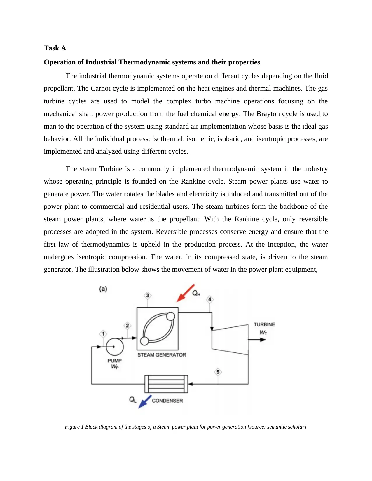
The steam Turbine is a commonly implemented thermodynamic system in the industry
whose operating principle is founded on the Rankine cycle. Steam power plants use water to
generate power. The water rotates the blades and electricity is induced and transmitted out of the
power plant to commercial and residential users. The steam turbines form the backbone of the
steam power plants, where water is the propellant. With the Rankine cycle, only reversible
processes are adopted in the system. Reversible processes conserve energy and ensure that the
first law of thermodynamics is upheld in the production process. At the inception, the water
undergoes isentropic compression. The water, in its compressed state, is driven to the steam
generator. The illustration below shows the movement of water in the power plant equipment,
Figure 1 Block diagram of the stages of a Steam power plant for power generation [source: semantic scholar]
Operation of Industrial Thermodynamic systems and their properties
The industrial thermodynamic systems operate on different cycles depending on the fluid
propellant. The Carnot cycle is implemented on the heat engines and thermal machines. The gas
turbine cycles are used to model the complex turbo machine operations focusing on the
mechanical shaft power production from the fuel chemical energy. The Brayton cycle is used to
man to the operation of the system using standard air implementation whose basis is the ideal gas
behavior. All the individual process: isothermal, isometric, isobaric, and isentropic processes, are
implemented and analyzed using different cycles.
The steam Turbine is a commonly implemented thermodynamic system in the industry
whose operating principle is founded on the Rankine cycle. Steam power plants use water to
generate power. The water rotates the blades and electricity is induced and transmitted out of the
power plant to commercial and residential users. The steam turbines form the backbone of the
steam power plants, where water is the propellant. With the Rankine cycle, only reversible
processes are adopted in the system. Reversible processes conserve energy and ensure that the
first law of thermodynamics is upheld in the production process. At the inception, the water
undergoes isentropic compression. The water, in its compressed state, is driven to the steam
generator. The illustration below shows the movement of water in the power plant equipment,
Figure 1 Block diagram of the stages of a Steam power plant for power generation [source: semantic scholar]

Figure 2 Temperature- Specific Entropy diagram and Carnot Cycle
Some of the thermodynamic systems are adiabatic while others are reversible. Reversible
systems are desired as they uphold the first law of thermodynamics which focusses on the
conservation of energy. The device produces maximum benefits for a specified amount of
resources. The process efficiency of a thermodynamic system and process is determined by the
reversibility of the processes (Jones, 2007). A set of the key factors that could impact the process
efficiency include heat loss in the form of friction. This heat loss causes the irreversibility of
certain processes that ought to follow through on the Isentropic process. The result of the friction
on the thermodynamic system is irreversibility which accrues the isentropic efficiency. The
efficiency seeks to determine the process efficacy or system performance. It is, therefore, a ratio
given as,
ηiso ,turbine= h¿−heirr
h¿−herev
The properties of thermodynamic systems are,
(i) A thermodynamic system exists in a closed or open boundary. It may be closed using
control or fixed mass or may be open in the case of a flowing mass or a movable or
stationary mass.
⊘ This is a preview!⊘
Do you want full access?
Subscribe today to unlock all pages.
Trusted by 1+ million students worldwide
(ii) Thermodynamic systems seek to attain a certain level of equilibrium where the
system properties are invariable. These systems are independent of mass and density
of the system parameters.
(iii) Thermodynamic extensive property tends to vary directly with mass. The systems are
based on processes and cycles. The processes denote paths from one state to a
different state.
(iv) These systems are exposed to environmental factors which affect the operation or the
processes of the system. During the design of the system, all these processes are taken
into consideration as they affect the duration and energy required to move the system
from one state to the other (Barrow, n.d.).
(v) The thermodynamic systems are governed by four laws namely the zeroth law, first
law, second law and third law of thermodynamics. All these laws demonstrate the
relationship between the thermodynamic systems with other environmental factors
surrounding the system in the cycle.
Application of the first law of thermodynamics to industrial systems.
THE CONSERVATION OF ENERGY LAW
The first law of thermodynamics states that during any given process or cycle that a control mass
system undergoes, the integral of heat about the cycle is proportional to the integral of work
about the same cycle or process (Eric Hendriks*†, et al., 2010). It is denoted as,
J∮ δQ=∮ δW
The cyclic integral of the heat transfer represents the net heat transfer during the cycle while the
cyclic integral of the work characterizes the net work done during the entire cycle (Edmister,
2005). There is a proportionality factor that depends solely on the units of work and heat denoted
as, J=4.1860 Joules /cal. The changes in the cycle are as denoted in the graphical illustration
below,
Paraphrase This Document
Need a fresh take? Get an instant paraphrase of this document with our AI Paraphraser
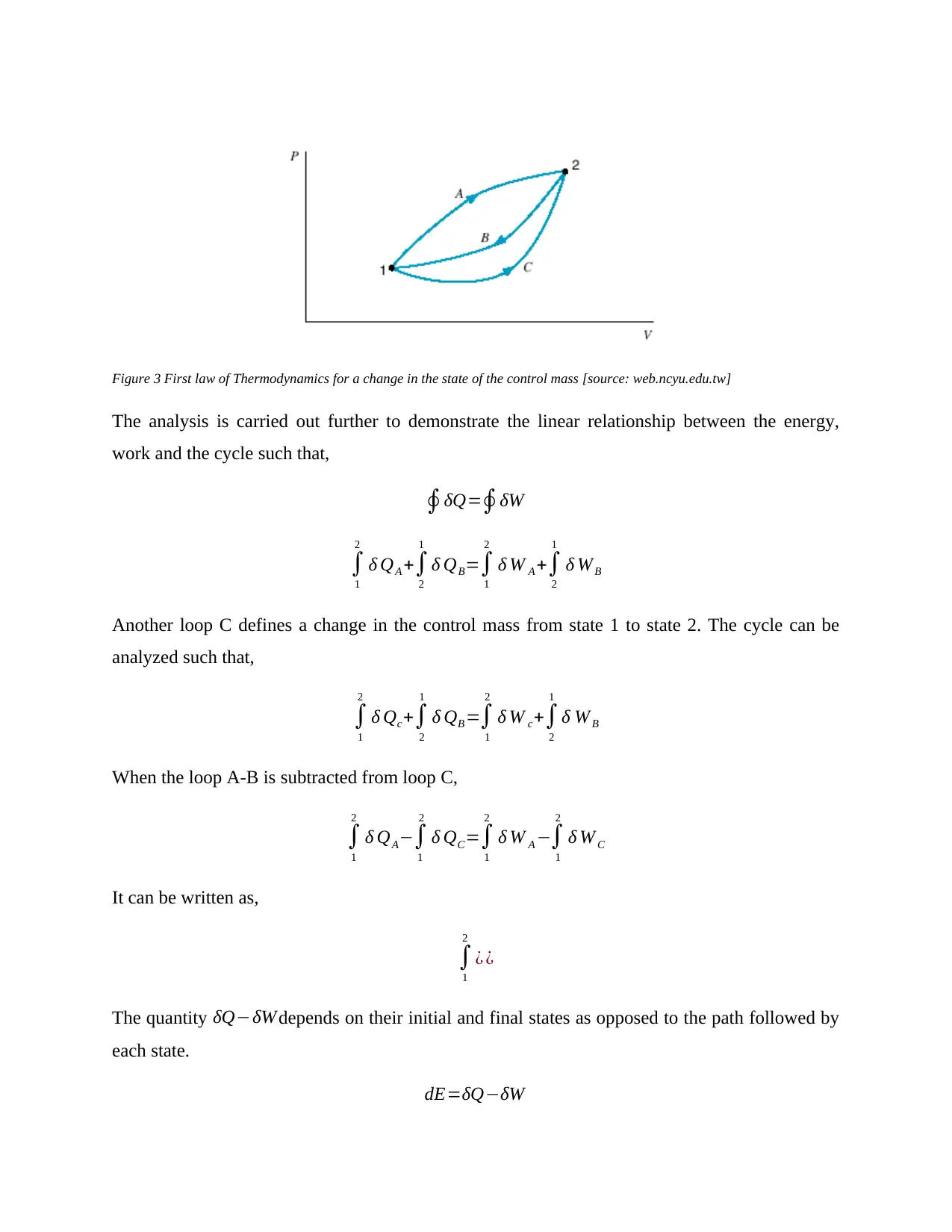
Figure 3 First law of Thermodynamics for a change in the state of the control mass [source: web.ncyu.edu.tw]
The analysis is carried out further to demonstrate the linear relationship between the energy,
work and the cycle such that,
∮δQ=∮δW
∫
1
2
δ QA +∫
2
1
δ QB=∫
1
2
δ W A +∫
2
1
δ WB
Another loop C defines a change in the control mass from state 1 to state 2. The cycle can be
analyzed such that,
∫
1
2
δ Qc+∫
2
1
δ QB =∫
1
2
δ W c+∫
2
1
δ W B
When the loop A-B is subtracted from loop C,
∫
1
2
δ QA−∫
1
2
δ QC=∫
1
2
δ W A −∫
1
2
δ W C
It can be written as,
∫
1
2
¿ ¿
The quantity δQ−δW depends on their initial and final states as opposed to the path followed by
each state.
dE=δQ−δW
Based on the equation of the conservation of energy as illustrated above, the net change of the
energy of the control mass is always equal to the net transfer of the energy across the boundary
as heat and work. Energy can cross the frontier of a control mass as either heat or work (Powers,
2018).
The industrial thermodynamic systems apply the first law of thermodynamics to support their
operations. One main application is in the heat engines, heat exchangers, commercial or public
heater and compressor systems, boilers, and turbines in the steam power plants. According to
Rudolf Clausius (1850), the law of energy conservation is based on the fact that energy cannot be
created or destroyed, rather it changes from one form to another.
Relationships between system constants for a perfect gas
An ideal gas is seen to interact with other parameters in its environment such that,
PV ( volume )=N R T
¿ N ( number of moles of gas ∈V )
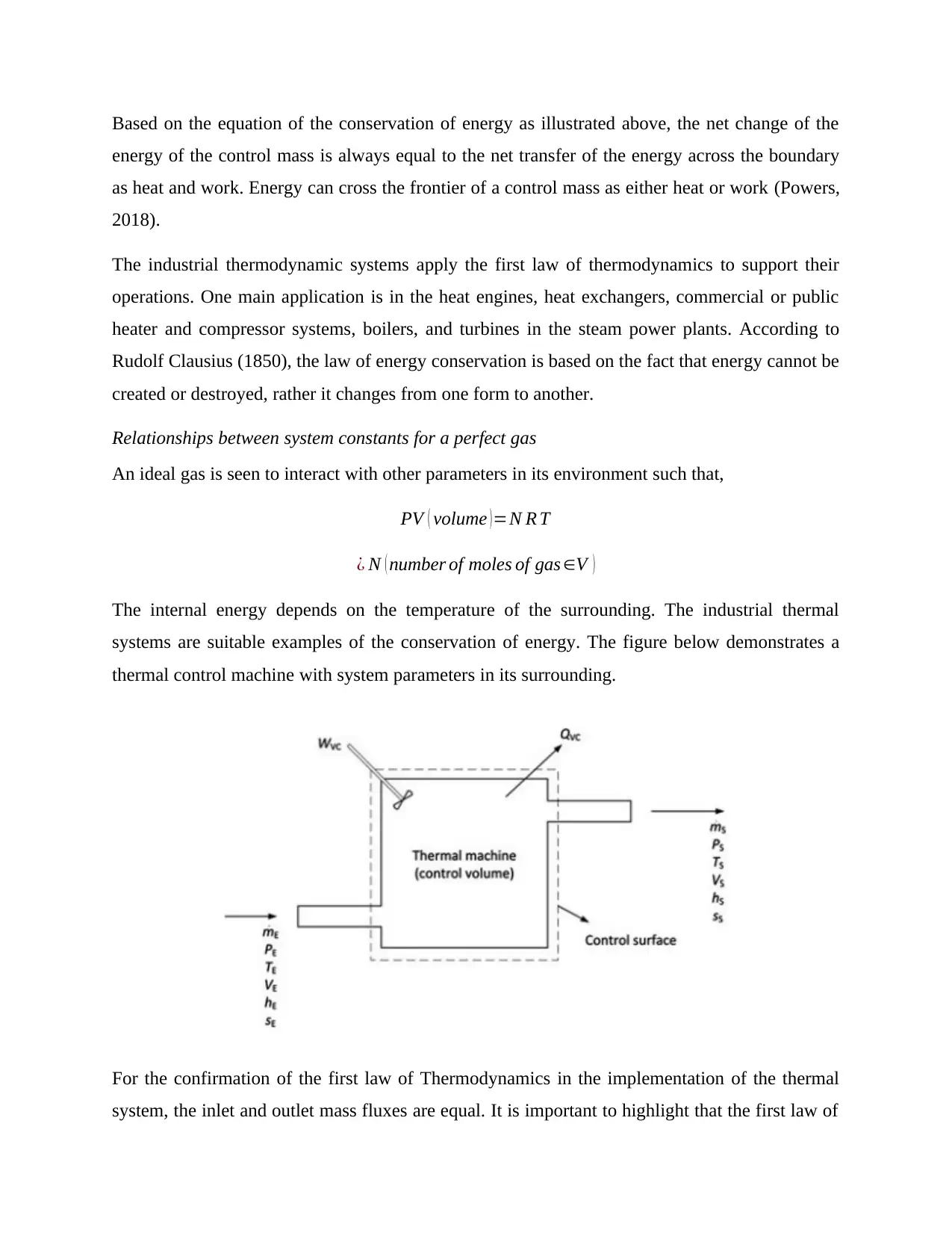
The internal energy depends on the temperature of the surrounding. The industrial thermal
systems are suitable examples of the conservation of energy. The figure below demonstrates a
thermal control machine with system parameters in its surrounding.
For the confirmation of the first law of Thermodynamics in the implementation of the thermal
system, the inlet and outlet mass fluxes are equal. It is important to highlight that the first law of
energy of the control mass is always equal to the net transfer of the energy across the boundary
as heat and work. Energy can cross the frontier of a control mass as either heat or work (Powers,
2018).
The industrial thermodynamic systems apply the first law of thermodynamics to support their
operations. One main application is in the heat engines, heat exchangers, commercial or public
heater and compressor systems, boilers, and turbines in the steam power plants. According to
Rudolf Clausius (1850), the law of energy conservation is based on the fact that energy cannot be
created or destroyed, rather it changes from one form to another.
Relationships between system constants for a perfect gas
An ideal gas is seen to interact with other parameters in its environment such that,
PV ( volume )=N R T
¿ N ( number of moles of gas ∈V )
The internal energy depends on the temperature of the surrounding. The industrial thermal
systems are suitable examples of the conservation of energy. The figure below demonstrates a
thermal control machine with system parameters in its surrounding.
For the confirmation of the first law of Thermodynamics in the implementation of the thermal
system, the inlet and outlet mass fluxes are equal. It is important to highlight that the first law of
⊘ This is a preview!⊘
Do you want full access?
Subscribe today to unlock all pages.
Trusted by 1+ million students worldwide
thermodynamics does not work in isolation. Other laws like the rate of entropy, the heat enthalpy
under the second law of thermodynamics, and reversibility analysis also apply to determine the
cumulative operation of the thermodynamic system (José, 2012).
Index of compression in polytrophic processes. Analyze an operational industrial
thermodynamic system regarding work done.
Thermodynamic systems implement both the first and second laws in the design of thermal
systems. Some of the thermal systems commonly studied in thermodynamics are the internal
combustion engines and the gas turbines. They are developed by the standard air cycles which
are analyzed using the ideal gas behavior and transformations. The polytrophic process follows
the pressure and volume relationship such that,
P V n=const
n=polytrophic coefficient
The polytrophic process can analyze all the individual reversible processes at a go. Some of the
processes analyzed are the isothermal, isochoric, isobaric, and isentropic processes. The
relationship between pressure, temperature, and polytrophic coefficient in the individual
processes is related as,
Process P S V T n
Isobaric Constant Varies 0
Isothermal Varies Constant 1
Isentropic Constant Gamma
Isochoric Constan
t
∞
A reversible process is denoted such as,
w=−∫
P 1
Po
vdP=−const ∫
P 1
P 2
dP
P
1
n
For the isothermal process, n=1,
Paraphrase This Document
Need a fresh take? Get an instant paraphrase of this document with our AI Paraphraser
¿−∫
P 1
Po
vdP=−const ∫
P 1
P 2
dP
P =−P1 v1 ln ( P2
P1 )=−P2 v2 ln ( P2
P1 )=−RT ln ( P2
P1 )
For other processes, where n=0,
¿−∫
P 1
Po
vdP=−const ∫
P 1
P 2
dP
P
1
n
= −n
n−1 ( P2 v2 −P1 v1 ) =−nR
n−1 ( T 2−T 1 )
From an ideal gas transformation equation, the ICE and gas turbines are modeled using the
Brayton and Diesel cycles which are air standard cycles. The polytrophic process is given as,
Wor kdone=∫ cdV
V n
¿ P1 V 1−P2 V 2
n−1 =wor kdone
dE=δQ−δW
E2− E1=q− P1 V 1−P2 V 2
n−1
E2− E1=Cv ( T 2−T 1 )=q−w
q= R ( T2−T 1 )
γ −1 + P1 V 1−P2 V 2
n−1
q=R ( T 1−T 2 ) {( 1
n−1 )− ( 1
γ −1 ) }
q= ( P1 V 1−P2 V 2
n−1 ) { γ −n
γ −1 }
q=w∗{ γ −n
γ −1 }
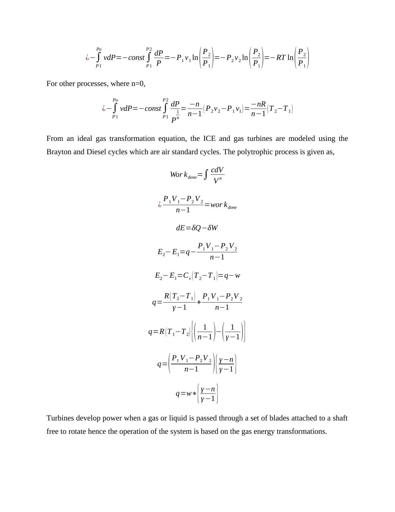
Turbines develop power when a gas or liquid is passed through a set of blades attached to a shaft
free to rotate hence the operation of the system is based on the gas energy transformations.
P 1
Po
vdP=−const ∫
P 1
P 2
dP
P =−P1 v1 ln ( P2
P1 )=−P2 v2 ln ( P2
P1 )=−RT ln ( P2
P1 )
For other processes, where n=0,
¿−∫
P 1
Po
vdP=−const ∫
P 1
P 2
dP
P
1
n
= −n
n−1 ( P2 v2 −P1 v1 ) =−nR
n−1 ( T 2−T 1 )
From an ideal gas transformation equation, the ICE and gas turbines are modeled using the
Brayton and Diesel cycles which are air standard cycles. The polytrophic process is given as,
Wor kdone=∫ cdV
V n
¿ P1 V 1−P2 V 2
n−1 =wor kdone
dE=δQ−δW
E2− E1=q− P1 V 1−P2 V 2
n−1
E2− E1=Cv ( T 2−T 1 )=q−w
q= R ( T2−T 1 )
γ −1 + P1 V 1−P2 V 2
n−1
q=R ( T 1−T 2 ) {( 1
n−1 )− ( 1
γ −1 ) }
q= ( P1 V 1−P2 V 2
n−1 ) { γ −n
γ −1 }
q=w∗{ γ −n
γ −1 }
Turbines develop power when a gas or liquid is passed through a set of blades attached to a shaft
free to rotate hence the operation of the system is based on the gas energy transformations.
The turbine is a steam power plant is modeled by taking into consideration the kinetic and
potential energy of the system. The turbine is modeled such that,
0= ˙Qcv− ˙W cw + ˙m [ ( h1−h2 ) + v1
2−v2
2
2 + g ( z1 −z2 ) ]
Assuming that the kinetic and potential energies are dropped out from the model,
0= ˙Qcv− ˙W cw + ˙m [ ( h1−h2 ) ]
When the heat transfer in the surrounding is considered negligible, the ˙Qcv is dropped, hence,
− ˙W cw + ˙m [ ( h1−h2 ) ] =0
˙W cw = ˙m(h1−h2)
In a nutshell, the index of compression, for the quasi-equilibrium process is dependent on
the individual process (Sullivan, 2013); it could be isobaric, isometric, and isothermal processes
as illustrated in the table above.
Task B
Illustrate the properties of viscosity in fluids. Discuss the three viscosity measurement
techniques
In fluid mechanics, the viscosity quantitatively measures the fluid resistance to flow.
Fluid is observed to deform continuously, as the fluid flows from one point to another. They are
subject to shear forces only when in motion, but no shear forces affect them while at rest. It can
⊘ This is a preview!⊘
Do you want full access?
Subscribe today to unlock all pages.
Trusted by 1+ million students worldwide
be dynamic or kinematic such that when the fluid resistance to flow is measured concerning
relative shearing motion, it is considered dynamic viscosity,
η= F
[ A∗( u
h ) ]
η= τ
( u
h ) [N −s/ m2 ]
When the resistance to is a ratio of the absolute viscosity to the density of fluid,
η
ρ =v
The viscosity index is used to accurately determine the viscosity-temperature
characteristics of oils or heavy kinds of fluids. It is given as,
VI (viscosity index)= L−U
L−H ∗10
Pressure has a huge effect on the viscosity of lubricants, especially if the pressure is
above the standard atmospheric pressure. The Barus equation:
ηp =η0 eαp
Analyze the effects of shear force on Newtonian fluids
According to fluid mechanics, the shear stresses for fluids in motion are developed when
the fluid molecules and particles move relative to each other. The particles move at different
velocities and direction; hence the fluid shape is distorted while in motion. One suitable example
is the motion of water on the slab surface. Fluids are a category that factors in water, oils,
lubricants, and gases. The liquids are difficult to compress, hence incompressible while the gases
are easy to compress as the particles of a gaseous substance are scattered over a large volume of
space. Some of the fluids that are termed as Newtonian fluids are air, water, oil, alcohol,
kerosene, Benzene, Glycerin, and gasoline. All these fluids obey the Newtonian law of viscosity.
The law is denoted as,
Paraphrase This Document
Need a fresh take? Get an instant paraphrase of this document with our AI Paraphraser
τ (shear stress)=μ du
dy
The shear stress is given as a ratio of the velocity gradient. The viscosity is a function
only of the condition of the fluid based on its temperature. There is a linear association between
the shear stress and the velocity gradient such that the slope and the viscosity are constant. The
cohesion and interaction of the fluid particle during motion determines the resistance to shear
deformation. The deformation of a fluid depends on the viscosity such that,
Deformatio nrate ∝ 1
viscosity … . fluids
τ ∝ y … stress vs . strain rate
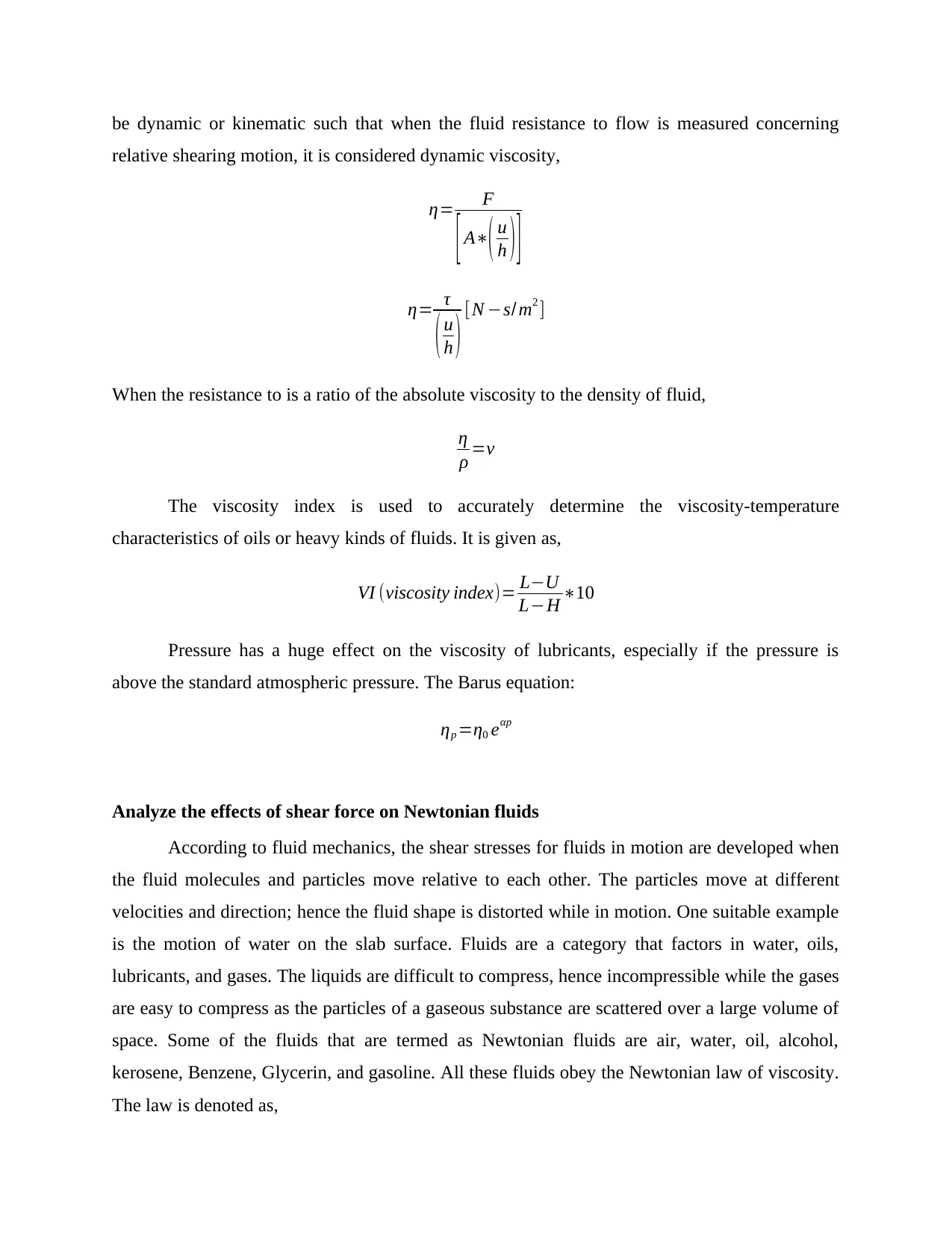
The Newtonian fluids have a linear relationship between the stress and strain. The rate of
deformation is directly proportional to the shear stress forces ratio and as a result, there is, a one-
dimensional system relationship as denoted by the law of viscosity. A number of fluids have
been shown in the following illustration; they tend to demonstrate the behavior. The dynamic
viscosity is given as,
Figure 4 Variation of the Shear-stress with rate of deformation
The temperature in the fluid’s surrounding affects the viscosity such that for liquids, an
increase in temperature reduces the viscosity, whereas, for gases, an increase in temperature
dy
The shear stress is given as a ratio of the velocity gradient. The viscosity is a function
only of the condition of the fluid based on its temperature. There is a linear association between
the shear stress and the velocity gradient such that the slope and the viscosity are constant. The
cohesion and interaction of the fluid particle during motion determines the resistance to shear
deformation. The deformation of a fluid depends on the viscosity such that,
Deformatio nrate ∝ 1
viscosity … . fluids
τ ∝ y … stress vs . strain rate
The Newtonian fluids have a linear relationship between the stress and strain. The rate of
deformation is directly proportional to the shear stress forces ratio and as a result, there is, a one-
dimensional system relationship as denoted by the law of viscosity. A number of fluids have
been shown in the following illustration; they tend to demonstrate the behavior. The dynamic
viscosity is given as,
Figure 4 Variation of the Shear-stress with rate of deformation
The temperature in the fluid’s surrounding affects the viscosity such that for liquids, an
increase in temperature reduces the viscosity, whereas, for gases, an increase in temperature
causes an increase in the viscosity. The Sutherland’s correlation is used in the analysis of
viscosity for gases with respect to temperature. It is denoted as,
μ
μ0
=
( T
T 0 ) 3
2
( T 0 +S
T +S )
Compare the results of viscosity test on a Newtonian fluid with that which is given on a
data sheet and explain any discrepancies.
Fluid η0 β k Nominal Viscous
behavior
S60 (N1) 0.137 13.5 0.1 Newtonian
DMS T25 (N2) 0.485 5.5 0.16 Newtonian
N1000 (N3) 2.867 5.6 0.1 Newtonian
Water 0.0010 6.7 0.5 Newtonian
Glycerol-water-PEO solution (T=22.50
C)
0.0155 . 0.4 Weakly shear-
thining
Aqueous xanthan gum solution
(T=220C)
11.5 . . Strongly shear
thining
CPyCl/NaSal micellar solution
(T=220C)
14.5 . . Shear banding
There is a slight discrepancy from the theoretical datasheet information such that the
deviation is on the scale of 0.56 percent. This is a negligible discrepancy which may be caused
by environmental factors such as the changes in temperature of the surrounding during the time
the laboratory tests were being carried out. The shear forces tested on the thermodynamic
equipment during manufacture may be different during the practical implementation. Some of
the factors to consider in such cases include:
(i) Wear and tear of the inner sections or irregularity in the structure of the equipment
especially in pipe systems and hydraulic machines. The flow may be affected
especially if the system is not designed to accommodate the turbulent flow.
(ii) The use of Newtonian fluid with some impurities. The impurities may affect some of
the parameters that determine the viscosity coefficient of a fluid during flow.
Impurities affect the density, particle-to-particle velocity due to increased random
collisions. The velocity changes which affects the rate of flow.
⊘ This is a preview!⊘
Do you want full access?
Subscribe today to unlock all pages.
Trusted by 1+ million students worldwide
1 out of 25
Related Documents


Your All-in-One AI-Powered Toolkit for Academic Success.
+13062052269
info@desklib.com
Available 24*7 on WhatsApp / Email
![[object Object]](/_next/static/media/star-bottom.7253800d.svg)
Unlock your academic potential
Copyright © 2020–2026 A2Z Services. All Rights Reserved. Developed and managed by ZUCOL.