Def/Ref Lab: Three-Phase Systems & Power Measurement Analysis

Verified

Added on  2022/12/05

|9
|1302
|325
Practical Assignment
AI Summary
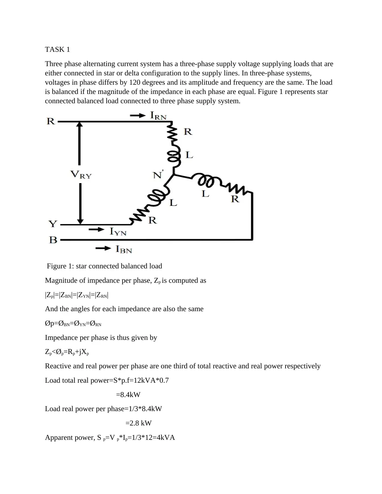
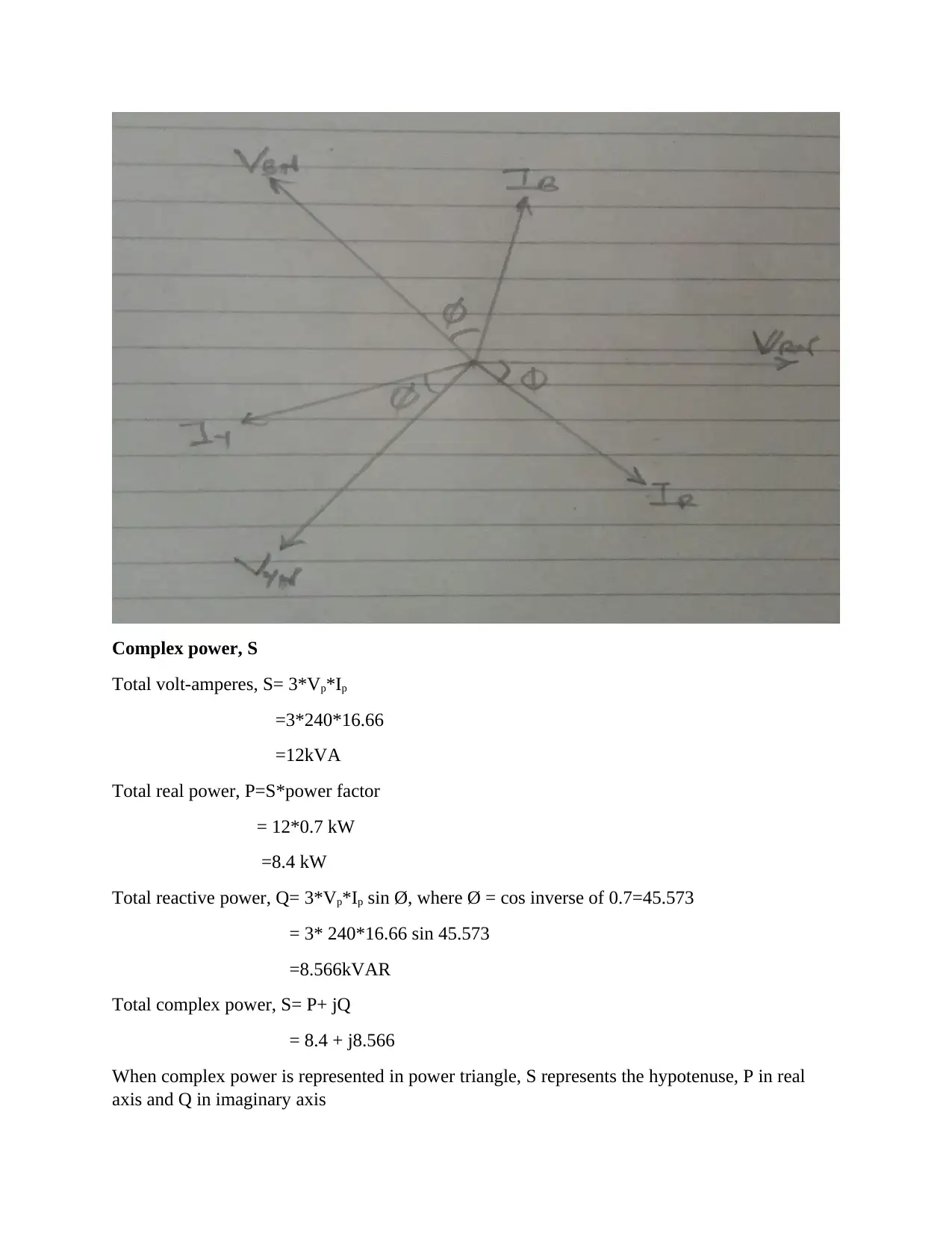
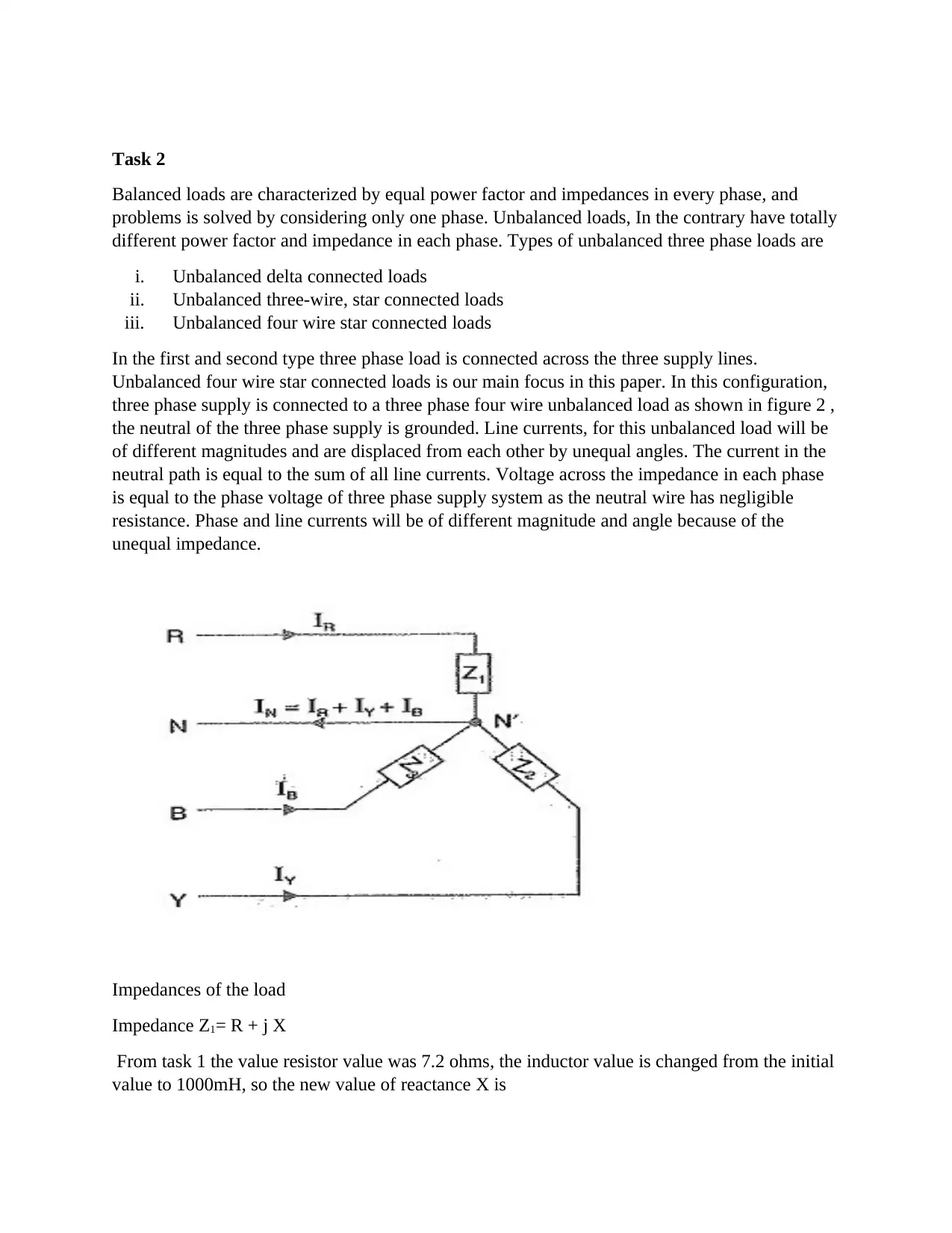
This assignment solution analyzes three-phase AC systems, addressing both balanced and unbalanced loads. Task 1 focuses on a balanced star-connected load, calculating equivalent resistance and inductance, voltages, currents, and complex power, supported by a phasor diagram. Task 2 introduces an unbalanced load scenario, modifying the inductance and capacitance in different phases, and examining the effects on voltages, currents, and power calculations. The solution includes detailed calculations of impedances, phase currents, neutral current, and complex power for both balanced and unbalanced conditions, providing a comprehensive understanding of three-phase system behavior under varying load conditions. The solution provides a step-by-step breakdown of each part of the assignment, complete with formulas and explanations.
tabler-icon-diamond-filled.svg

Contribute Materials

Your contribution can guide someone’s learning journey. Share your documents today.
Document Page
TASK 1
Three phase alternating current system has a three-phase supply voltage supplying loads that are
either connected in star or delta configuration to the supply lines. In three-phase systems,
voltages in phase differs by 120 degrees and its amplitude and frequency are the same. The load
is balanced if the magnitude of the impedance in each phase are equal. Figure 1 represents star
connected balanced load connected to three phase supply system.
Figure 1: star connected balanced load
Magnitude of impedance per phase, Zp is computed as
|Zp|=|ZBN|=|ZYN|=|ZRN|
And the angles for each impedance are also the same
Øp=ØBNYNRN
Impedance per phase is thus given by
Zpp=Rp+jXp
Reactive and real power per phase are one third of total reactive and real power respectively
Load total real power=S*p.f=12kVA*0.7
=8.4kW
Load real power per phase=1/3*8.4kW
=2.8 kW
Apparent power, S p=V p*Ip=1/3*12=4kVA
tabler-icon-diamond-filled.svg

Secure Best Marks with AI Grader

Need help grading? Try our AI Grader for instant feedback on your assignments.
Document Page
For star connected load, phase voltage V p= VL*1/square root of 3 =415*1/root 3=240 V
Current flowing through blue-phase
power consumed per phase by the load, P= V*I*cos Ø
lagging power factor of 0.7 means current lags voltage by angle of cos inverse 0.7 = 45.57
IBN=Sp/VBN
= 4000/240
=16.667<74.43
Impedance in each phase is calculated as
Z p=VBN/IBN
= (240<120) / (16.667<74.43) = 14.4<45.57
=10.08 + j10.28
= R +JX
Value of R is thus 10.08 Ω
X=2*π*f*L, where f is frequency of the source and L is the inductance
L=10.28/2*π*50
=32.7 mH
Voltages and currents
For star connected load, phase voltage V p= VL*1/3 =415*1/3=240 V
All phase voltages are 120 degrees out of phase
Phase voltage in red to neutral is given
VRN=240<00 V
Phase voltage in yellow to neutral is
VYN= 240<-1200 V
Phase voltage in blue to neutral is
VBY=240<1200 V
For star connected load line current is equal to phase current
IL = Ip
Document Page
Current in red phase
IRN=VRN/ZP, but Z p=14.4 (calculated in the previous exercise)
=240<0/14.4
= 16.66<-45.57
Current in yellow phase
IYN= VYN/ZP, but Z p=14.4
=240/14.4
= 16.66<-165.57
Current in blue phase
IBN=VBN/ZP, but Z p=14.4
=240/14.4
= 16.66<74.43
Phasor diagram
Phase voltages are
VRN=240<00 V
VYN=240<-1200V
VBN=240<1200V
Phase currents
IRN=16.66<-45.570 A
IYN= 16.66<-165.570 A
IBN= 16.66<74.430 A
Lengths of the phasor represents the magnitude of voltages and currents
Document Page
Complex power, S
Total volt-amperes, S= 3*Vp*Ip
=3*240*16.66
=12kVA
Total real power, P=S*power factor
= 12*0.7 kW
=8.4 kW
Total reactive power, Q= 3*Vp*Ip sin Ø, where Ø = cos inverse of 0.7=45.573
= 3* 240*16.66 sin 45.573
=8.566kVAR
Total complex power, S= P+ jQ
= 8.4 + j8.566
When complex power is represented in power triangle, S represents the hypotenuse, P in real
axis and Q in imaginary axis
tabler-icon-diamond-filled.svg

Secure Best Marks with AI Grader

Need help grading? Try our AI Grader for instant feedback on your assignments.
Document Page
Task 2
Balanced loads are characterized by equal power factor and impedances in every phase, and
problems is solved by considering only one phase. Unbalanced loads, In the contrary have totally
different power factor and impedance in each phase. Types of unbalanced three phase loads are
i. Unbalanced delta connected loads
ii. Unbalanced three-wire, star connected loads
iii. Unbalanced four wire star connected loads
In the first and second type three phase load is connected across the three supply lines.
Unbalanced four wire star connected loads is our main focus in this paper. In this configuration,
three phase supply is connected to a three phase four wire unbalanced load as shown in figure 2 ,
the neutral of the three phase supply is grounded. Line currents, for this unbalanced load will be
of different magnitudes and are displaced from each other by unequal angles. The current in the
neutral path is equal to the sum of all line currents. Voltage across the impedance in each phase
is equal to the phase voltage of three phase supply system as the neutral wire has negligible
resistance. Phase and line currents will be of different magnitude and angle because of the
unequal impedance.
Impedances of the load
Impedance Z1= R + j X
From task 1 the value resistor value was 7.2 ohms, the inductor value is changed from the initial
value to 1000mH, so the new value of reactance X is
Document Page
X= 2 * π * f * L
= 2 * π* 50 *1
= 314.2
Impedance Z1= 10 + j 314.2
Impedance Z2= R+ j X
Resistor value is 10 ohms, inductor is replaced with a capacitor of 15uF capacitance, so a new
reactance value X is
X= 1 / (2 * π * F * C)
=1 / (2 * π * 50 * 15 * 10^-6
= 212.2
Impedance Z2= 10 + j 212.2
And impedance Z3 remained unchanged from task 1
Impedance Z3= 10 + j 10.3
Phase voltages calculations
Voltage across each impedance is equal to the supply phase voltage
Red phase voltage is
VRN=240<00 V
Yellow phase voltage is
VYN=240<-1200V
Blue phase voltage is
VBN=240<1200V
Phase currents calculations
Current in red phase
IRN = VRN/Z1
= (240 < 0)/ (10 + j 314.2)
= 0.764<-88.70 A
Current in yellow phase
Document Page
IYN = VYN/Z2
= (240 < -120) / (10 + j212.2)
= 1.13 <- 1520 A
Current in blue phase
IBN = VBN/Z3
= (240 < 120) / (10 + j10.3)
= 16.71 < 74.20 A
Neutral current is given by
IN= IRN + IYN + IBN
= 15.96<62.60
Phasor diagram
Phase voltages are
VRN=240<00 V
VYN=240<-1200V
VBN=240<1200V
Phase currents
IRN = 0.764<-88.70 A
IYN = 1.13 <-1520 A
IBN = 16.71 < 710 A
IN= 15.96<62.60
tabler-icon-diamond-filled.svg

Paraphrase This Document

Need a fresh take? Get an instant paraphrase of this document with our AI Paraphraser
Document Page
Complex power for unbalanced load
Total volt-amperes, S is found by adding apparent power for each phase thus
Total S = VRN*IRN + VBN*IBN + VYN*IYN
= (240*0.764) + (240*1.13) + (240*16.64)
=4.448kVA
Total real is found by adding real power for each phase, where each phase has different power
factor. Formula for real power, P=S*p.f, power factor is angle difference between phase current
and phase voltage
Total real power, P= (240*0.764* cos 88.7) + (240*1.13 * cos 32) + (240*16.64*cos 60)
= 2.230 kW
Total reactive power is found by adding reactive power for the three phases. Formula for
calculating reactive power, Q= Vp*Ip sin Ø, where Ø is identical for each phase
Total reactive power, Q = (240*0.764* sin 88.7) + (240*1.13 * sin 32) + (240*16.64*sin 60)
= 3.786 kVAR
Total complex power, S= P+ jQ
Document Page
= 2.230 + 3.786
When complex power is represented in power triangle, S represents the hypotenuse, P in real
axis and Q in imaginary axis
chevron_up_icon
1 out of 9
circle_padding
hide_on_mobile
zoom_out_icon
logo.png

Your All-in-One AI-Powered Toolkit for Academic Success.

Available 24*7 on WhatsApp / Email

[object Object]