Mechanical Engineering: Three-Phase Horizontal Separator Design Report
VerifiedAdded on 2019/10/18
|22
|6063
|360
Report
AI Summary
This report focuses on the design of a three-phase horizontal separator used in the oil and gas industry. It begins with background information on hydrocarbon separation and the need for separators, highlighting the types and functions of separators. The methodology section explains the gravity segregation principle, the role of inlet devices, and the factors affecting separation efficiency, such as flow rate, pressure, and the presence of impurities. The report delves into the theory of separation, including settling velocity calculations, the concept of drag coefficient, and the importance of retention time. It also covers gas and liquid capacity constraints, providing equations and considerations for separator sizing. The report emphasizes the critical aspects of the design process, providing a comprehensive understanding of the key parameters and calculations involved in designing a three-phase horizontal separator.
CHAPTER ONE
1.0 Background
Hydrocarbons which are produced from wells whether oil or gas are not in the form of simple mixtures but of very complex
form of liquid or gas mixture of hundreds of different composites of chemically bonded compounds. A well stream typically
is turbulent of mixed substances such as gas, oil, water including minerals of dissolved form containing a substantial
amount of salt, corrosive gasses such as Carbon dioxide (CO2) and Hydrogen sulfide (H2S), and different solids e.g. sands of
unconsolidated forms producing intervals on a reservoir from which particles of sands may become detached at the
slightest flow rate of production. Therefore, the need for separation processes to align these components to their export
standards and bring about the flow of branched-out but simultaneous components is carried out by the separator.
Nonetheless, the types of separators used in the oil and gas industry are three which vary in terms of both form and
function such as Horizontal separator, vertical separator and spherical separator. The Horizontal type can be subdivided
into even further sections such as single tube and double tubes. Both horizontal and vertical separators may be classed as
two phase and or three phase separators, this depends on their specifications and purposes. Depending on the objective
targeted, a two phase separator will be used for the separation of a two phase only (oil-gas) or (gas-water) separation and a
three phase separator is used for the separation of a gas from water and gas equally. Among the entire field processing
operations, the separation of a gas from free-liquid has shown to be the most critical stage. The desired size of a particular
separation unit is equally (directly) proportional to that of a composition of fluid mixture and pressure. Hence, this project
aims to demonstrate for the design of a three-phase horizontal separator, whilst considering factors that influences the
design of a separator including; oil and gas capacity constraints, bending moments and stress, design materials, cost for
design amongst others.
However, Guo, B. et al, (2007) argues that separators function on the basis of gravity segregation/settling or centrifugal
segregation. The separator construction normally depends on the:
Inlet device, where the primary separation of gas-liquid bulk occurs.
A large settling section of adequate height or length to allow for liquid droplets.
Equipped with a mist extractor near the gas outlet to coalesce any entrained liquid droplets that do not settle due to
gravity.
adequate controls, such as: liquid level controller, placed between oil-water level and in the oil section, liquid dump valves,
gas back-pressure valve, pressure gauges, instrument gas regulator and piping.
Paraphrase This Document
Need a fresh take? Get an instant paraphrase of this document with our AI Paraphraser

2
CHAPTER TWO
2.0 Methodology
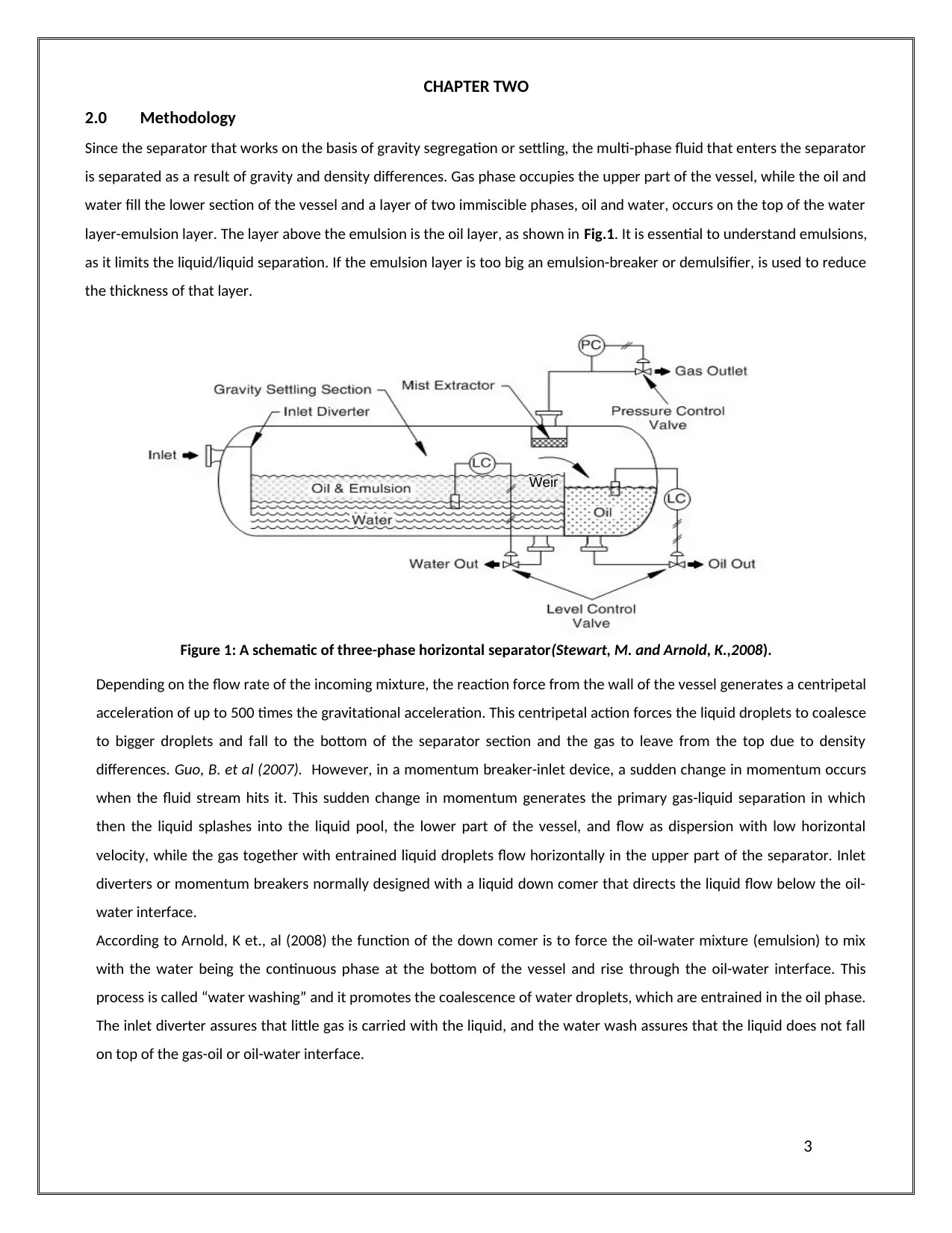
Since the separator that works on the basis of gravity segregation or settling, the multi-phase fluid that enters the separator
is separated as a result of gravity and density differences. Gas phase occupies the upper part of the vessel, while the oil and
water fill the lower section of the vessel and a layer of two immiscible phases, oil and water, occurs on the top of the water
layer-emulsion layer. The layer above the emulsion is the oil layer, as shown in Fig.1. It is essential to understand emulsions,
as it limits the liquid/liquid separation. If the emulsion layer is too big an emulsion-breaker or demulsifier, is used to reduce
the thickness of that layer.
Figure 1: A schematic of three-phase horizontal separator(Stewart, M. and Arnold, K.,2008).
Depending on the flow rate of the incoming mixture, the reaction force from the wall of the vessel generates a centripetal
acceleration of up to 500 times the gravitational acceleration. This centripetal action forces the liquid droplets to coalesce
to bigger droplets and fall to the bottom of the separator section and the gas to leave from the top due to density
differences. Guo, B. et al (2007). However, in a momentum breaker-inlet device, a sudden change in momentum occurs
when the fluid stream hits it. This sudden change in momentum generates the primary gas-liquid separation in which
then the liquid splashes into the liquid pool, the lower part of the vessel, and flow as dispersion with low horizontal
velocity, while the gas together with entrained liquid droplets flow horizontally in the upper part of the separator. Inlet
diverters or momentum breakers normally designed with a liquid down comer that directs the liquid flow below the oil-
water interface.
According to Arnold, K et., al (2008) the function of the down comer is to force the oil-water mixture (emulsion) to mix
with the water being the continuous phase at the bottom of the vessel and rise through the oil-water interface. This
process is called “water washing” and it promotes the coalescence of water droplets, which are entrained in the oil phase.
The inlet diverter assures that little gas is carried with the liquid, and the water wash assures that the liquid does not fall
on top of the gas-oil or oil-water interface.
3
Weir
2.0 Methodology
Since the separator that works on the basis of gravity segregation or settling, the multi-phase fluid that enters the separator
is separated as a result of gravity and density differences. Gas phase occupies the upper part of the vessel, while the oil and
water fill the lower section of the vessel and a layer of two immiscible phases, oil and water, occurs on the top of the water
layer-emulsion layer. The layer above the emulsion is the oil layer, as shown in Fig.1. It is essential to understand emulsions,
as it limits the liquid/liquid separation. If the emulsion layer is too big an emulsion-breaker or demulsifier, is used to reduce
the thickness of that layer.
Figure 1: A schematic of three-phase horizontal separator(Stewart, M. and Arnold, K.,2008).
Depending on the flow rate of the incoming mixture, the reaction force from the wall of the vessel generates a centripetal
acceleration of up to 500 times the gravitational acceleration. This centripetal action forces the liquid droplets to coalesce
to bigger droplets and fall to the bottom of the separator section and the gas to leave from the top due to density
differences. Guo, B. et al (2007). However, in a momentum breaker-inlet device, a sudden change in momentum occurs
when the fluid stream hits it. This sudden change in momentum generates the primary gas-liquid separation in which
then the liquid splashes into the liquid pool, the lower part of the vessel, and flow as dispersion with low horizontal
velocity, while the gas together with entrained liquid droplets flow horizontally in the upper part of the separator. Inlet
diverters or momentum breakers normally designed with a liquid down comer that directs the liquid flow below the oil-
water interface.
According to Arnold, K et., al (2008) the function of the down comer is to force the oil-water mixture (emulsion) to mix
with the water being the continuous phase at the bottom of the vessel and rise through the oil-water interface. This
process is called “water washing” and it promotes the coalescence of water droplets, which are entrained in the oil phase.
The inlet diverter assures that little gas is carried with the liquid, and the water wash assures that the liquid does not fall
on top of the gas-oil or oil-water interface.
3
Weir
⊘ This is a preview!⊘
Do you want full access?
Subscribe today to unlock all pages.
Trusted by 1+ million students worldwide
2.1 Factors Affecting Separation Processes
There are some factors that affect the separation efficiency in a separator. The following factors must be determined
before separation design:
Flow Rate of Gas and liquid.
Operating and design pressures and temperature
Physical properties of the fluid such as , Z, , Sg, etc.,
Surging or slugging tendencies of feed streams.
Size of droplet to be removed.
Presence of impurities e.g: Paraffin, sand, scale, etc.,
Foaming tendencies of the crude oil,
Corrosive tendencies of the liquid or gas.
Arnold, K. 2007, reported challenges associated with separation processes such as:
Foaming: Pressure reduction in certain types of crude oils may produce foaming. It occurs when small bubbles of gases
that are dissolved in the oil start to come out of solution, and are incased in a thin film of oil.
Emulsion: Materials become emulsified due to the presence of oil and water at the same time. The liquid/liquid
separation will be limited, if a large emulsion layer exists.
Corrosion: Produced well fluids can be very corrosive and may cause the primary failure of process equipment. The two
most corrosive elements are hydrogen sulfide and carbon dioxide. These two gases may present in the well fluids in
quantities from a race up to 40% to 50% of the gas by volume.
Paraffin: The deposition of paraffin in separators could reduce their efficiency through the build-up action inside the
vessel. Paraffin build-up may block the fluid passages and the mist extractor, and consequently leads to costly operation
shut downs.
Sand: When dealing with separators, sand could have a worrying effect; as it is capable of causing metal erosion,
especially in valves and chocks. In addition, it can accumulate at the bottom of the separator leading to blockage or
clogging of the separator internals.
4
Paraphrase This Document
Need a fresh take? Get an instant paraphrase of this document with our AI Paraphraser
2.2 THEORY OF SEPARATION
2.3 Settling velocity
In a three-phase separator, the upper part represents the gravity settling section of the gas-phase in which oil droplets are
entrained with the gas. The relative motion exists between oil droplets and the surrounding gas. An oil droplet, being
denser than the surrounding gas tends to move vertically downwards due to gravitational or buoyant force, F g, while the
surrounding gas exerts a drag force on the opposite direction of that oil droplet, Fd. Consequently, the oil droplet will
accelerate downward until the drag force balances the gravitational or buoyant force; and therefore, the droplet will fall at
a uniform velocity, known as terminal or settling velocity.
The low half of the three-phase separator is occupied by the liquid phase (oil and water). The retention time constraint of
the liquid in a three-phase separator must be considered for both oil droplets in water and water droplets in oil. Similar to
gas settling section, in separating oil droplets from water or water droplets from oil, a relative motion exists between the
droplet and the surrounding continuous phase.
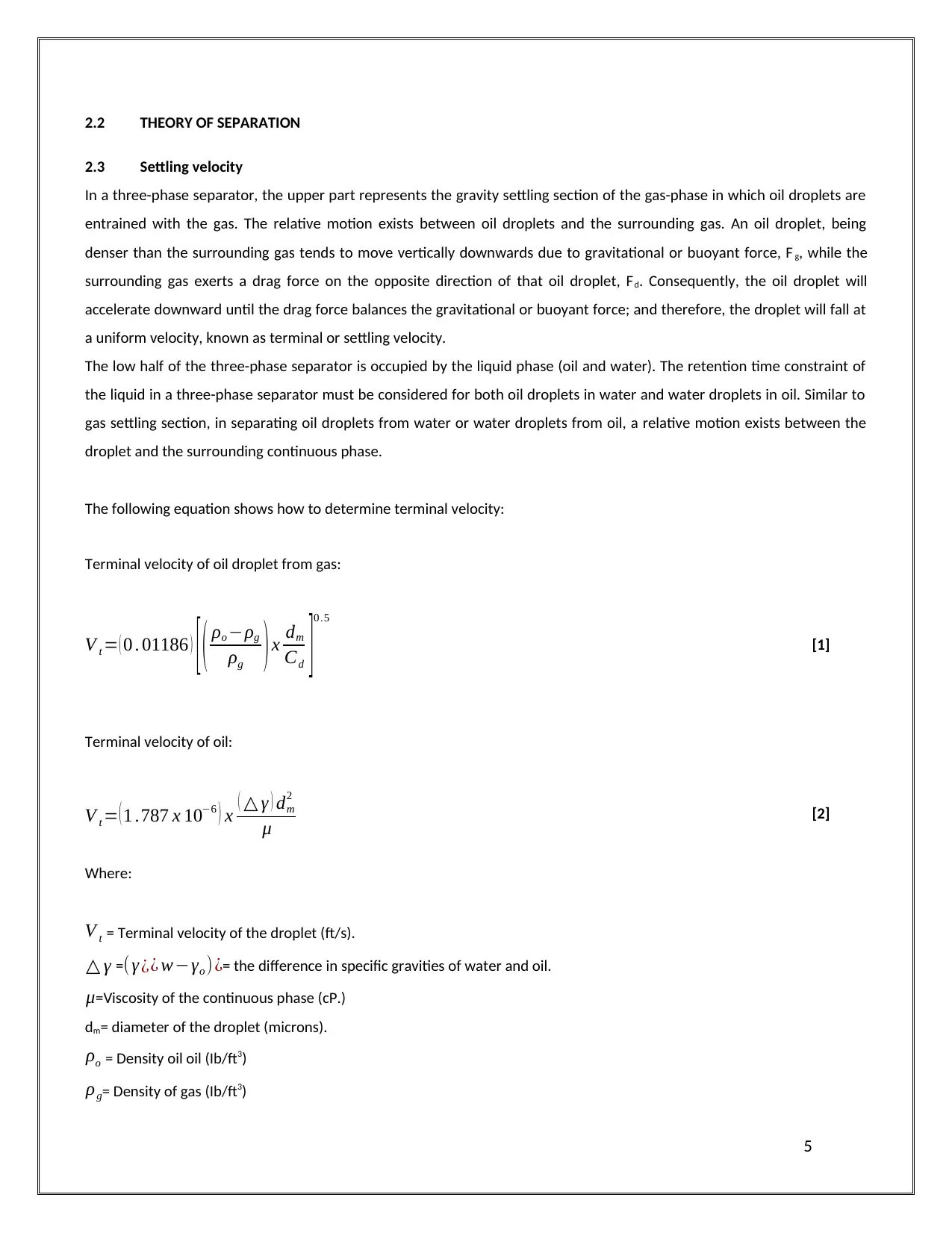
The following equation shows how to determine terminal velocity:
Terminal velocity of oil droplet from gas:
V t = ( 0 . 01186 ) [ ( ρo −ρg
ρg )x dm
Cd ]0 .5
[1]
Terminal velocity of oil:
V t = ( 1 .787 x 10−6 ) x ( △ γ ) dm
2
μ [2]
Where:
V t = Terminal velocity of the droplet (ft/s).
△ γ =(γ ¿¿ w−γo )¿= the difference in specific gravities of water and oil.
μ=Viscosity of the continuous phase (cP.)
dm= diameter of the droplet (microns).
ρo = Density oil oil (Ib/ft3)
ρg= Density of gas (Ib/ft3)
5
2.3 Settling velocity
In a three-phase separator, the upper part represents the gravity settling section of the gas-phase in which oil droplets are
entrained with the gas. The relative motion exists between oil droplets and the surrounding gas. An oil droplet, being
denser than the surrounding gas tends to move vertically downwards due to gravitational or buoyant force, F g, while the
surrounding gas exerts a drag force on the opposite direction of that oil droplet, Fd. Consequently, the oil droplet will
accelerate downward until the drag force balances the gravitational or buoyant force; and therefore, the droplet will fall at
a uniform velocity, known as terminal or settling velocity.
The low half of the three-phase separator is occupied by the liquid phase (oil and water). The retention time constraint of
the liquid in a three-phase separator must be considered for both oil droplets in water and water droplets in oil. Similar to
gas settling section, in separating oil droplets from water or water droplets from oil, a relative motion exists between the
droplet and the surrounding continuous phase.
The following equation shows how to determine terminal velocity:
Terminal velocity of oil droplet from gas:
V t = ( 0 . 01186 ) [ ( ρo −ρg
ρg )x dm
Cd ]0 .5
[1]
Terminal velocity of oil:
V t = ( 1 .787 x 10−6 ) x ( △ γ ) dm
2
μ [2]
Where:
V t = Terminal velocity of the droplet (ft/s).
△ γ =(γ ¿¿ w−γo )¿= the difference in specific gravities of water and oil.
μ=Viscosity of the continuous phase (cP.)
dm= diameter of the droplet (microns).
ρo = Density oil oil (Ib/ft3)
ρg= Density of gas (Ib/ft3)
5
CD = Drag coefficient.
In considering equation 2, the settling velocity of a droplet is inversely proportional to the viscosity of the continuous
phase. Knowing that the viscosity of oil is several times higher than that of the water, therefore the terminal velocity of oil
droplets in water is greater than the terminal velocity of water droplet in the oil. Since, the required time for a droplet to
settle out of one continuous phase and reach the oil-water interface depends on the terminal velocity and the distance
traveled by the droplet, therefore the separation of water droplets from the continuous oil phase would always be taken as
the design criterion for three-phase separators (Abdel-Aal, H., et al, 2003).
2.4 Drag coefficient ( CD)
The drag coefficient (CD) concept, mentioned previously, is very important in separator designs and it is a function of
Reynolds number and the shape of particle of the flowing gas. For the purpose of design, the shape of the particle is
considered to be a solid, rigid sphere. The value of the drag coefficient can be determined using trial-and-error solution,
since both particle size (dm) and terminal velocity (Vt) are involved.
According to (Stewart, M. and Arnold, K., 2008), for production facility design, Stokes’ law does not govern, and the
following formula for drag coefficient must be used instead.
CD =0 . 34+ 24
Re
+ 3
¿ ¿¿ ¿ [3]
The terminal velocity is given by equations (1 and 4), when the drag force acting on the droplet is equal to the buoyant
force:
V t =0 . 01186 x ¿ ¿ [4]
Re=(0 . 0049) x ρg x dm x V t
μ [5]
Where:
Re = Reynolds number (dimensionless).
2.5 Retention time
According to (Stewart, M. and Arnold, K.,2008), retention time is one of the important aspects that need to be taken into
consideration when designing a separator. It can be defined as the following “the average time a molecule of liquid is
retained in the vessel, assuming plug flow”. It determines the required liquid volumes within the separator, so in other
words, it is the volume of liquid storage in the vessel divided by liquid flow rate. In a three-phase separator, a sufficient
6
⊘ This is a preview!⊘
Do you want full access?
Subscribe today to unlock all pages.
Trusted by 1+ million students worldwide
period of time has to be given for the oil to reach equilibrium for the dissolved gas to be liberated. Retention time has to be
long enough for water droplets, entrained in the oil, to coalesce and settle to water zone. Simultaneously, water phase
needs to be retained for sufficient period of time to allow for the coalescence of oil droplets, suspended in water.
2.6 Gas capacity
According to Arnold, K., and Steward, M. (2008), the principles of liquid droplets settling from a gas bulk to liquid-gas
interface can be used to develop an equation to size a separator for a gas flow rate. The gas capacity constraint equations
are based on setting the gas retention time equal to the time required for a droplet to settle to the liquid interface. Fora
half-full horizontal vessel of liquid, and separation of 100 micron liquid droplets from the gas, the following equation may
be used:
d Leff =240 x [ TZ Qg
P ] x [ [ ρg
ρl −ρg ][ Cd
dm ] ]1/ 2
[1]
Where:
d = vessel internal diameter (inches).
Leff = the effective length of the vessel where separation occurs (ft).
T = operating temperature (° R ¿.
Qg= gas flow rate (MMscf/day).
P = operating pressure (psia).
Z = gas compressibility.
CD = drag coefficient.
dm = liquid droplet to be separated (micron).
ρg= density of gas (Ib/ft3).
ρl = density of liquid (Ib/ft3).
2.7 Liquid Capacity Retention Time Constraint
The separator size must provide sufficient space for the oil and water such that each phase is retained adequately within
the separator. The assumption used is that the liquid will occupy half of the separator volume, as Stewart, M. and Arnold,
K., (2008) suggested. However, in the present case, both oil and water occupy that volume. Therefore, the volume occupied
by the liquid-phase (both oil and water), VL, is the sum of the volume occupied by oil (Vo) and water(Vw) in a separator
having a diameter, D (in.), and effective length, L (ft). So the combination of vessel diameter (d) and effective length (L eff)
can be calculated using the following equation:
D2Leff = 1.429¿ [7]
Where:
7
Paraphrase This Document
Need a fresh take? Get an instant paraphrase of this document with our AI Paraphraser
Qw = water flow rate (bbl/day).
¿ = water retention time (min.).
( Qo )= oil flow rate (bbl/day).
¿ = oil retention time (min.).
d = vessel internal diameter (inches).
Leff = the effective length of the vessel where separation occurs (ft)
2.8 Seam-to-Seam length
The effective length where the phase separation occurs can be determined, if the liquid retention time constraint governs,
otherwise equation (6) can be used to determine the effective length. From this, a vessel seam-to-seam length may be
determined. The actual seam-to-seam length depends on the physical design of the internals in a vessel Fig.3.
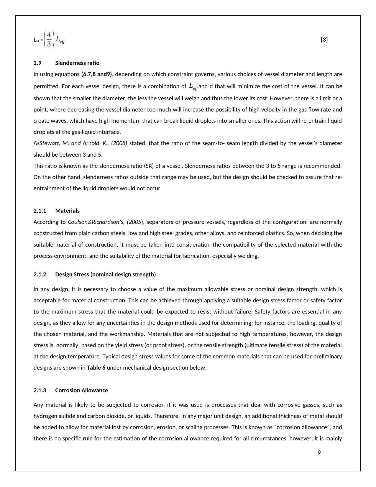
Some vessels are sized based on a gas capacity constraint; therefore, some portion of the vessel length is required to
distribute the flow evenly near the inlet diverter.
Another portion of the vessel length is required for the mist extractor. The length of the vessel between the inlet diverter
and the mist extractor with evenly distributed flow is known as the effective vessel length ( Leff ¿. This effective length is
directly proportional to the diameter of the vessel, so as a vessel’s diameter increases more length is required to distribute
the flow of the gas evenly after the inlet diverter.
The seam-to-seam length can be determined from the following equation, if the gas capacity constraint governs:
Lss= Leff
12 [2]
Figure 1: a schematic of a horizontal separator showing the
effective and seam-to-seam lengths (Arnold, K., and Steward, M., 2008).
However, sizing a vesselwhere the liquid capacity governs, some portion of the vessel’s length must be considered for inlet
diverter flow distribution and liquid outlet. The seam-to-seam length should not exceed the following:
8
¿ = water retention time (min.).
( Qo )= oil flow rate (bbl/day).
¿ = oil retention time (min.).
d = vessel internal diameter (inches).
Leff = the effective length of the vessel where separation occurs (ft)
2.8 Seam-to-Seam length
The effective length where the phase separation occurs can be determined, if the liquid retention time constraint governs,
otherwise equation (6) can be used to determine the effective length. From this, a vessel seam-to-seam length may be
determined. The actual seam-to-seam length depends on the physical design of the internals in a vessel Fig.3.
Some vessels are sized based on a gas capacity constraint; therefore, some portion of the vessel length is required to
distribute the flow evenly near the inlet diverter.
Another portion of the vessel length is required for the mist extractor. The length of the vessel between the inlet diverter
and the mist extractor with evenly distributed flow is known as the effective vessel length ( Leff ¿. This effective length is
directly proportional to the diameter of the vessel, so as a vessel’s diameter increases more length is required to distribute
the flow of the gas evenly after the inlet diverter.
The seam-to-seam length can be determined from the following equation, if the gas capacity constraint governs:
Lss= Leff
12 [2]
Figure 1: a schematic of a horizontal separator showing the
effective and seam-to-seam lengths (Arnold, K., and Steward, M., 2008).
However, sizing a vesselwhere the liquid capacity governs, some portion of the vessel’s length must be considered for inlet
diverter flow distribution and liquid outlet. The seam-to-seam length should not exceed the following:
8
Lss =( 4
3 ) Leff [3]
2.9 Slenderness ratio
In using equations (6,7,8 and9), depending on which constraint governs, various choices of vessel diameter and length are
permitted. For each vessel design, there is a combination of Leff and d that will minimize the cost of the vessel. It can be
shown that the smaller the diameter, the less the vessel will weigh and thus the lower its cost. However, there is a limit or a
point, where decreasing the vessel diameter too much will increase the possibility of high velocity in the gas flow rate and
create waves, which have high momentum that can break liquid droplets into smaller ones. This action will re-entrain liquid
droplets at the gas-liquid interface.
AsStewart, M. and Arnold, K., (2008) stated, that the ratio of the seam-to- seam length divided by the vessel’s diameter
should be between 3 and 5.
This ratio is known as the slenderness ratio (SR) of a vessel. Slenderness ratios between the 3 to 5 range is recommended.
On the other hand, slenderness ratios outside that range may be used, but the design should be checked to assure that re-
entrainment of the liquid droplets would not occur.
2.1.1 Materials
According to Coulson&Richardson’s, (2005), separators or pressure vessels, regardless of the configuration, are normally
constructed from plain carbon steels, low and high steel grades, other alloys, and reinforced plastics. So, when deciding the
suitable material of construction, it must be taken into consideration the compatibility of the selected material with the
process environment, and the suitability of the material for fabrication, especially welding.
2.1.2 Design Stress (nominal design strength)
In any design, it is necessary to choose a value of the maximum allowable stress or nominal design strength, which is
acceptable for material construction. This can be achieved through applying a suitable design stress factor or safety factor
to the maximum stress that the material could be expected to resist without failure. Safety factors are essential in any
design, as they allow for any uncertainties in the design methods used for determining; for instance, the loading, quality of
the chosen material, and the workmanship. Materials that are not subjected to high temperatures, however, the design
stress is, normally, based on the yield stress (or proof stress), or the tensile strength (ultimate tensile stress) of the material
at the design temperature. Typical design stress values for some of the common materials that can be used for preliminary
designs are shown in Table 6 under mechanical design section below.
2.1.3 Corrosion Allowance
Any material is likely to be subjected to corrosion if it was used is processes that deal with corrosive gasses, such as
hydrogen sulfide and carbon dioxide, or liquids. Therefore, in any major unit design, an additional thickness of metal should
be added to allow for material lost by corrosion, erosion, or scaling processes. This is known as “corrosion allowance”, and
there is no specific rule for the estimation of the corrosion allowance required for all circumstances, however, it is mainly
9
⊘ This is a preview!⊘
Do you want full access?
Subscribe today to unlock all pages.
Trusted by 1+ million students worldwide
based on the experience with the material of construction under similar service conditions to those proposed for the new
design. As Coulson& Richardson’s, (2005) suggestions in the book, for carbon and low-alloy steels, where severe corrosion is
not expected, a minimum allowance of 2.0 mm should be used; where more severe conditions are expected minimum
thickness this should be increased to 4.0 mm. A minimum corrosion allowance of 1.0 mm is the standard in most of design
codes. Process design:
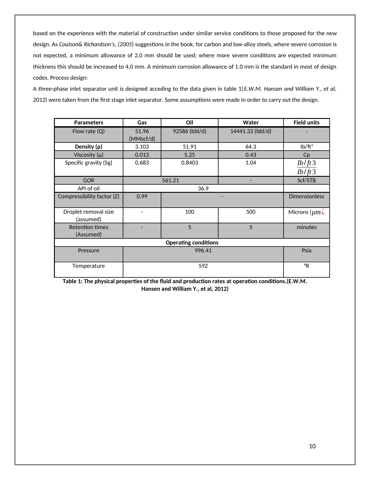
A three-phase inlet separator unit is designed acceding to the data given in table 1( E.W.M. Hansen and William Y., et al,
2012) were taken from the first stage inlet separator. Some assumptions were made in order to carry out the design.
Parameters Gas Oil Water Field units
Flow rate (Q) 51.96
(MMscf/d)
92586 (bbl/d) 14441.33 (bbl/d) -
Density (ρ) 3.103 51.91 64.3 Ib/ft3
Viscosity (μ) 0.013 5.25 0.43 Cp
Specific gravity (Sg) 0.683 0.8403 1.04 Ib / ft 3
Ib / ft 3
GOR 561.21 - Scf/STB
API of oil 36.9
Compressibility factor (Z) 0.99 - Dimensionless
Droplet removal size
(assumed)
- 100 500 Microns (μm ¿
Retention times
(Assumed)
- 5 5 minutes
Operating conditions
Pressure 996.41 Psia
Temperature 592 °R
Table 1: The physical properties of the fluid and production rates at operation conditions.(E.W.M.
Hansen and William Y., et al, 2012)
10
design. As Coulson& Richardson’s, (2005) suggestions in the book, for carbon and low-alloy steels, where severe corrosion is
not expected, a minimum allowance of 2.0 mm should be used; where more severe conditions are expected minimum
thickness this should be increased to 4.0 mm. A minimum corrosion allowance of 1.0 mm is the standard in most of design
codes. Process design:
A three-phase inlet separator unit is designed acceding to the data given in table 1( E.W.M. Hansen and William Y., et al,
2012) were taken from the first stage inlet separator. Some assumptions were made in order to carry out the design.
Parameters Gas Oil Water Field units
Flow rate (Q) 51.96
(MMscf/d)
92586 (bbl/d) 14441.33 (bbl/d) -
Density (ρ) 3.103 51.91 64.3 Ib/ft3
Viscosity (μ) 0.013 5.25 0.43 Cp
Specific gravity (Sg) 0.683 0.8403 1.04 Ib / ft 3
Ib / ft 3
GOR 561.21 - Scf/STB
API of oil 36.9
Compressibility factor (Z) 0.99 - Dimensionless
Droplet removal size
(assumed)
- 100 500 Microns (μm ¿
Retention times
(Assumed)
- 5 5 minutes
Operating conditions
Pressure 996.41 Psia
Temperature 592 °R
Table 1: The physical properties of the fluid and production rates at operation conditions.(E.W.M.
Hansen and William Y., et al, 2012)
10
Paraphrase This Document
Need a fresh take? Get an instant paraphrase of this document with our AI Paraphraser
Assumptions: Some assumptions were made for the purpose of carrying on the design of the three-phase separator, as
there was insufficient information about some of the data needed. Some of the required data for the design were taken
from Stewart, M. and Arnold, K. (2008)as assumed values. Assumptions were made: The specific gravity of the gas ( γg) is
assumed to be 0.683, and he compressibility factor of the gas Z = 0.99.
The gas flow rate is calculated based on the GOR = 100 sm3/sm3 (gas to oil ratio) and oil flow rate (Qo = 277758 bbl/day)
given in the following document (E.W.M. Hansen). The conversion of the GOR from sm3/sm3 to scf/STB is shown below:
∵ 1 (sm3) gas = 35.30 (sft3)
∵ 1 (sm3) oil = 6.29 (bbl)
∴ 1 sm3/sm3 = 35.30(ft3)
6.29(bbl)
∴ 100 sm3/sm3 = 561.21 (scf/STB)
∴gas flow rate (Qg) = flow rate of oil (Qo) x GOR
Qg = 277758 (bbl/d) x 561.21 (scf/STB) = 155.88 (MMscf/d)
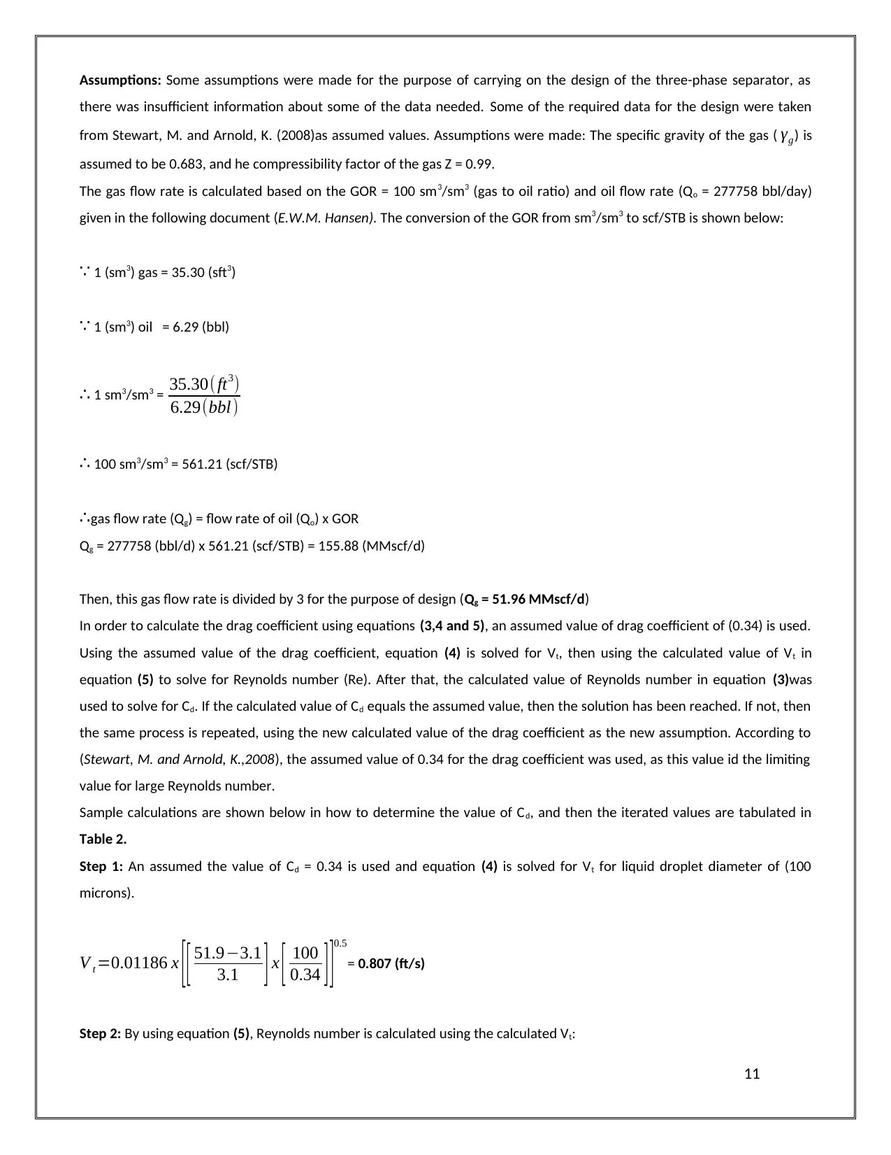
Then, this gas flow rate is divided by 3 for the purpose of design (Qg = 51.96 MMscf/d)
In order to calculate the drag coefficient using equations (3,4 and 5), an assumed value of drag coefficient of (0.34) is used.
Using the assumed value of the drag coefficient, equation (4) is solved for Vt, then using the calculated value of Vt in
equation (5) to solve for Reynolds number (Re). After that, the calculated value of Reynolds number in equation (3)was
used to solve for Cd. If the calculated value of Cd equals the assumed value, then the solution has been reached. If not, then
the same process is repeated, using the new calculated value of the drag coefficient as the new assumption. According to
(Stewart, M. and Arnold, K.,2008), the assumed value of 0.34 for the drag coefficient was used, as this value id the limiting
value for large Reynolds number.
Sample calculations are shown below in how to determine the value of Cd, and then the iterated values are tabulated in
Table 2.
Step 1: An assumed the value of Cd = 0.34 is used and equation (4) is solved for Vt for liquid droplet diameter of (100
microns).
V t =0.01186 x [ [ 51.9−3.1
3.1 ] x [ 100
0.34 ] ]0.5
= 0.807 (ft/s)
Step 2: By using equation (5), Reynolds number is calculated using the calculated Vt:
11
there was insufficient information about some of the data needed. Some of the required data for the design were taken
from Stewart, M. and Arnold, K. (2008)as assumed values. Assumptions were made: The specific gravity of the gas ( γg) is
assumed to be 0.683, and he compressibility factor of the gas Z = 0.99.
The gas flow rate is calculated based on the GOR = 100 sm3/sm3 (gas to oil ratio) and oil flow rate (Qo = 277758 bbl/day)
given in the following document (E.W.M. Hansen). The conversion of the GOR from sm3/sm3 to scf/STB is shown below:
∵ 1 (sm3) gas = 35.30 (sft3)
∵ 1 (sm3) oil = 6.29 (bbl)
∴ 1 sm3/sm3 = 35.30(ft3)
6.29(bbl)
∴ 100 sm3/sm3 = 561.21 (scf/STB)
∴gas flow rate (Qg) = flow rate of oil (Qo) x GOR
Qg = 277758 (bbl/d) x 561.21 (scf/STB) = 155.88 (MMscf/d)
Then, this gas flow rate is divided by 3 for the purpose of design (Qg = 51.96 MMscf/d)
In order to calculate the drag coefficient using equations (3,4 and 5), an assumed value of drag coefficient of (0.34) is used.
Using the assumed value of the drag coefficient, equation (4) is solved for Vt, then using the calculated value of Vt in
equation (5) to solve for Reynolds number (Re). After that, the calculated value of Reynolds number in equation (3)was
used to solve for Cd. If the calculated value of Cd equals the assumed value, then the solution has been reached. If not, then
the same process is repeated, using the new calculated value of the drag coefficient as the new assumption. According to
(Stewart, M. and Arnold, K.,2008), the assumed value of 0.34 for the drag coefficient was used, as this value id the limiting
value for large Reynolds number.
Sample calculations are shown below in how to determine the value of Cd, and then the iterated values are tabulated in
Table 2.
Step 1: An assumed the value of Cd = 0.34 is used and equation (4) is solved for Vt for liquid droplet diameter of (100
microns).
V t =0.01186 x [ [ 51.9−3.1
3.1 ] x [ 100
0.34 ] ]0.5
= 0.807 (ft/s)
Step 2: By using equation (5), Reynolds number is calculated using the calculated Vt:
11
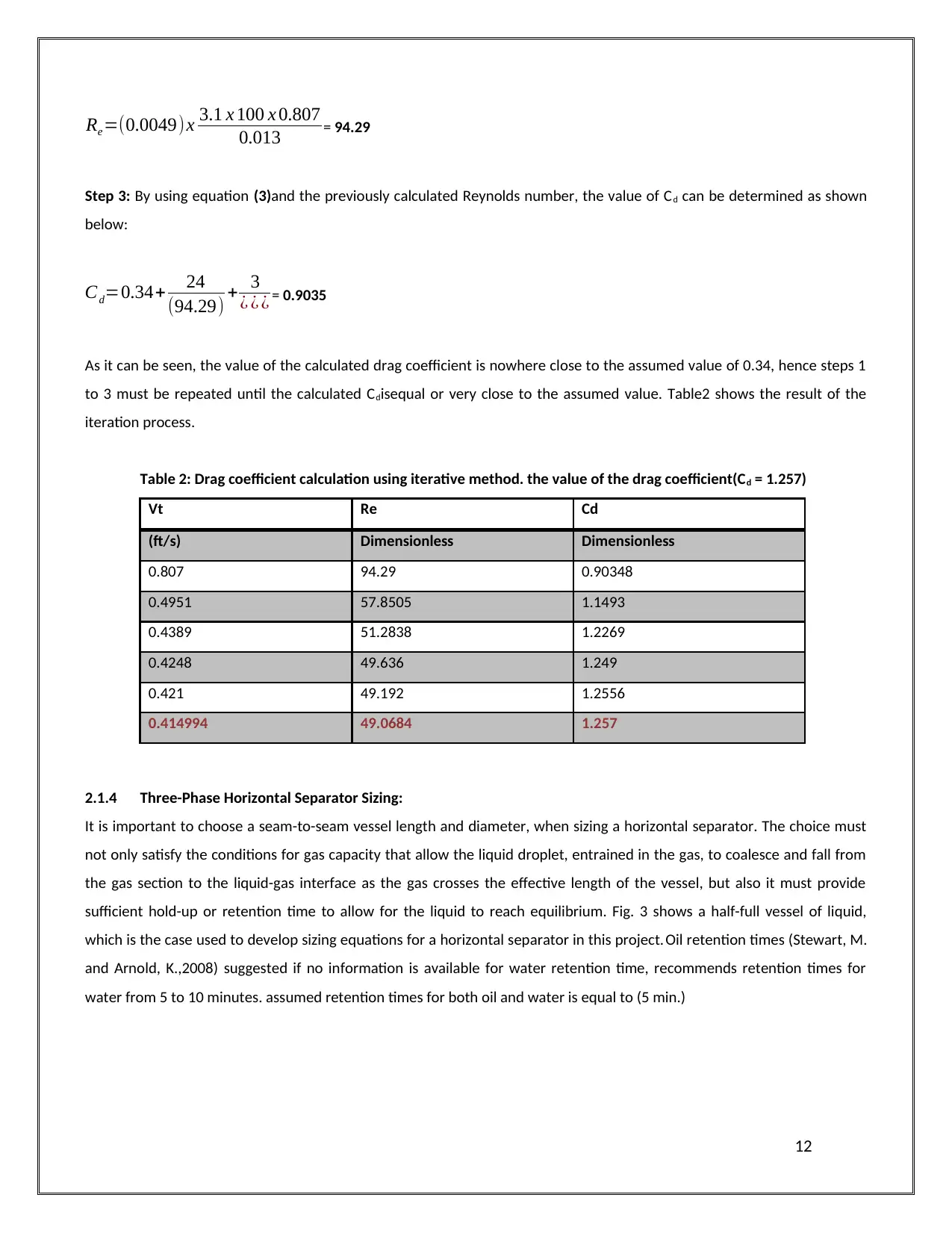
Re=(0.0049)x 3.1 x 100 x 0.807
0.013 = 94.29
Step 3: By using equation (3)and the previously calculated Reynolds number, the value of Cd can be determined as shown
below:
Cd=0.34+ 24
(94.29) + 3
¿ ¿ ¿ = 0.9035
As it can be seen, the value of the calculated drag coefficient is nowhere close to the assumed value of 0.34, hence steps 1
to 3 must be repeated until the calculated Cdisequal or very close to the assumed value. Table2 shows the result of the
iteration process.
Table 2: Drag coefficient calculation using iterative method. the value of the drag coefficient(Cd = 1.257)
Vt Re Cd
(ft/s) Dimensionless Dimensionless
0.807 94.29 0.90348
0.4951 57.8505 1.1493
0.4389 51.2838 1.2269
0.4248 49.636 1.249
0.421 49.192 1.2556
0.414994 49.0684 1.257
2.1.4 Three-Phase Horizontal Separator Sizing:
It is important to choose a seam-to-seam vessel length and diameter, when sizing a horizontal separator. The choice must
not only satisfy the conditions for gas capacity that allow the liquid droplet, entrained in the gas, to coalesce and fall from
the gas section to the liquid-gas interface as the gas crosses the effective length of the vessel, but also it must provide
sufficient hold-up or retention time to allow for the liquid to reach equilibrium. Fig. 3 shows a half-full vessel of liquid,
which is the case used to develop sizing equations for a horizontal separator in this project. Oil retention times (Stewart, M.
and Arnold, K.,2008) suggested if no information is available for water retention time, recommends retention times for
water from 5 to 10 minutes. assumed retention times for both oil and water is equal to (5 min.)
12
⊘ This is a preview!⊘
Do you want full access?
Subscribe today to unlock all pages.
Trusted by 1+ million students worldwide
1 out of 22

Your All-in-One AI-Powered Toolkit for Academic Success.
+13062052269
info@desklib.com
Available 24*7 on WhatsApp / Email
![[object Object]](/_next/static/media/star-bottom.7253800d.svg)
Unlock your academic potential
Copyright © 2020–2026 A2Z Services. All Rights Reserved. Developed and managed by ZUCOL.