Electrical Engineering Project: Three Phase Sequence Checker Report
VerifiedAdded on 2020/02/24
|9
|1735
|341
Report
AI Summary
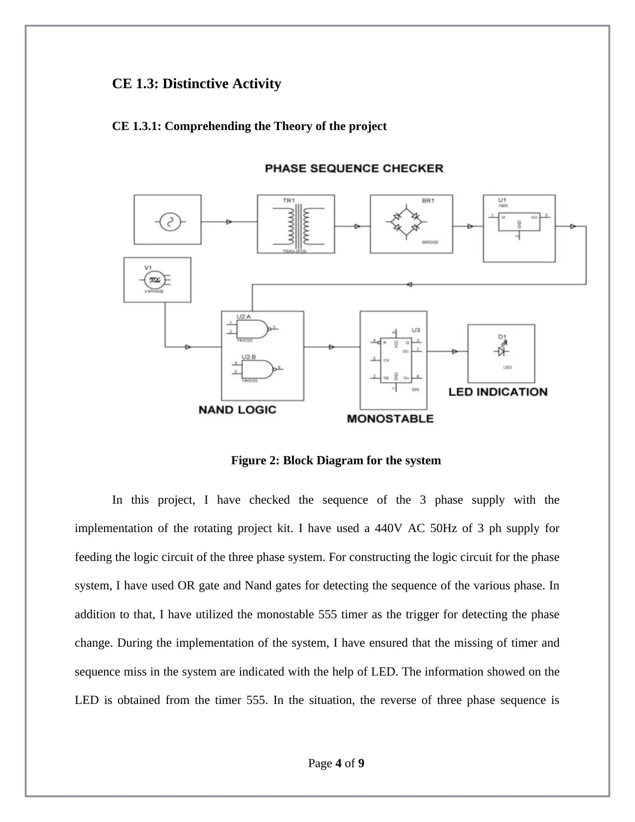
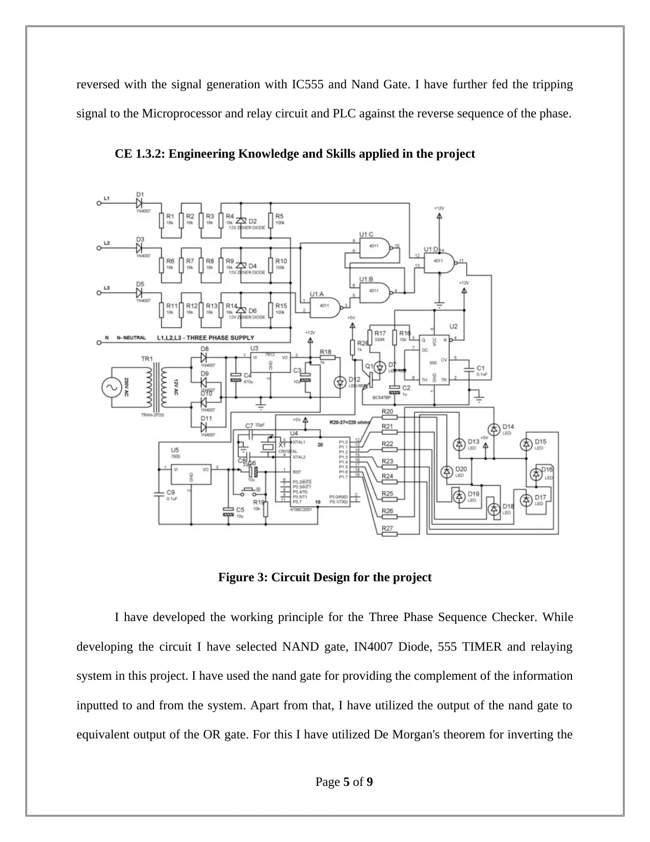
This report details a student's project on the development and implementation of a Three Phase Sequence Checker. The project aimed to identify the accurate time interval required for each phase to reach its maximum value in rotational machinery. The report covers the project's background, objectives, and the student's role as a team member. The student focused on circuit design, utilizing NAND gates, 555 timers, and relay circuits to detect phase sequence and implement a tripping mechanism for reverse phase sequences. The report includes details on the applied engineering knowledge, such as the use of the IN4007 diode and the 555 timer for pulse generation and delay. The project involved the design of a power supply, MATLAB simulations, and collaborative work. The report concludes with a project overview, highlighting the efficiency and reliability of the system in detecting phase sequence and reducing the risk of circuit overload. The student successfully completed the project within the given timeline, providing a practical solution for protecting machinery from damage caused by incorrect phase sequences.

Competency Demonstration Report (CDR)
Career Episode 1
CHENGAL REDDY UTUKUR
Career Episode 1
CHENGAL REDDY UTUKUR
Paraphrase This Document
Need a fresh take? Get an instant paraphrase of this document with our AI Paraphraser

CE 1.1: Project Introduction
Name of the Project : Three Phase Sequence Checker for Three Phase Supply
with Relay Circuit
Geographical Location : [Please Fill]
Project Duration : [Please Fill]
Organization : [Please Fill]
Position in the Project : Team Member
CE 1.2: Project Background
CE 1.2.1: Characteristics of the Project
In current days, various kinds of machineries and heavy equipments are used for the
manufacturing and other production related work. From evaluating various process and
mechanical machineries, I have observed that most of the machines are equipped with rotational
parts. In addition to that I have observed that the rotational machineries are equipped with phase
sequence meter for determining the supply sequence of the three-phase electric circuit. The 3
phase system generated the current or the rotated voltage that reaches the maximum or peak
value is obtained with the help of phase sequence. Various testers of phase sequence detector or
tests are available in the market for determining the phase but not the time required for achieving
the peak value. Therefore in this project I have tried to develop an appropriate system for
identifying the accurate time interval required for attaining the maximum value by each of the
phase in the rotational machineries.
Page 1 of 9

CE 1.2.2: Objectives developed for project
Various ranges of phase sequence detector and tester are used in various industries for
detecting the phase of the system. I have found that the testers are capable of using rotating,
static, non-contact and contact systems with wide range of power and voltage ratings. Therefore,
throughout the project, I have developed my significant aim to determine the sequence of three
phase sequence in clock wise direction. In addition to that,
I have utilized the LED kit of rotating project for the project. In addition to that, for easy
evaluation and design, I have confirmed the below stated objectives.
To determine the appropriate hardware component and technical module required for
the project;
To determining the working principle for the phase sequence checker;
To identify the working principle for the phase sequence checker;
To identify the components and develop the circuit diagram for demonstrating the
phase sequence checker;
To identify the response time when the three phase of the systems gets off;
CE 1.2.3: My area of work
I have worked alongside my team members for the completion of the design and
implementation of the Three Phase Sequence Checker. I was able to characterized the work into
two major module. In the first module I have demonstrated the theories and the calculation
required for implementation of the system. While in the second phase, I was associated with the
practical implementation and integration of the hardware and circuitry element required for the
project.
Page 2 of 9
⊘ This is a preview!⊘
Do you want full access?
Subscribe today to unlock all pages.

Trusted by 1+ million students worldwide

CE 1.2.4: Project Group
Figure 1: Team Member associated in this project
CE 1.2.5: My responsibilities throughout the project
In this project I have worked as a team member for the development and design of the
required Three Phase Sequence Checker. I have developed the working principle required for the
operation of the sequence checker. In addition to that, I was provided with the responsibility of
developing the required circuit diagram of the Three Phase Sequence Checker with the
application of the nand gate, relay and timers.
Page 3 of 9
Paraphrase This Document
Need a fresh take? Get an instant paraphrase of this document with our AI Paraphraser

CE 1.3: Distinctive Activity
CE 1.3.1: Comprehending the Theory of the project
Figure 2: Block Diagram for the system
In this project, I have checked the sequence of the 3 phase supply with the
implementation of the rotating project kit. I have used a 440V AC 50Hz of 3 ph supply for
feeding the logic circuit of the three phase system. For constructing the logic circuit for the phase
system, I have used OR gate and Nand gates for detecting the sequence of the various phase. In
addition to that, I have utilized the monostable 555 timer as the trigger for detecting the phase
change. During the implementation of the system, I have ensured that the missing of timer and
sequence miss in the system are indicated with the help of LED. The information showed on the
LED is obtained from the timer 555. In the situation, the reverse of three phase sequence is
Page 4 of 9

reversed with the signal generation with IC555 and Nand Gate. I have further fed the tripping
signal to the Microprocessor and relay circuit and PLC against the reverse sequence of the phase.
CE 1.3.2: Engineering Knowledge and Skills applied in the project
Figure 3: Circuit Design for the project
I have developed the working principle for the Three Phase Sequence Checker. While
developing the circuit I have selected NAND gate, IN4007 Diode, 555 TIMER and relaying
system in this project. I have used the nand gate for providing the complement of the information
inputted to and from the system. Apart from that, I have utilized the output of the nand gate to
equivalent output of the OR gate. For this I have utilized De Morgan's theorem for inverting the
Page 5 of 9
⊘ This is a preview!⊘
Do you want full access?
Subscribe today to unlock all pages.

Trusted by 1+ million students worldwide

output of the nand gate. Further, I have utilized the IN4007 Diode as the full wave and half wave
rectifier for converting the Ac current to required DC current. While designing the IN4007
Diode, I have ensured the maximum voltage capacity, maximum reverse capacity and maximum
forward current required for the three phase checker. Apart from that I have used the 555 timer
for utilization in the oscillator applications, pulse generation, and variety of timers in the Three
Phase Sequence Checker. During the development of the Three Phase Sequence Checker, I have
utilized the 555 timer for providing delay in over the system and acting as a flip flop element.
Through this I was able to achieve four timing circuits within one package with application of
the 555 timer. Further, in this project I have utilized 555 timer as the required electronic
oscillator for the development of Three Phase Sequence Checker. Furthermore, I have integrated
the 555 timer as the required pulse generator and detecting any missing pulse send through the
application.
CE 1.3.3: Accomplishment and Task Performed
In this project, I have worked for establishing secure power supply for the Three Phase
Sequence Checker. I have used 2230 V AC, 50 Hz power input through 12 V step down
transformer. I have further inputted the AC current to the bridge rectifier for converting to
required DC current. Furthermore, I have used 470 μf filters that further inputted the power to
regulator that finally provided the required 5V of Dc current that was essential for operating
Three Phase Sequence Checker.
CE 1.3.4: Identified Issues and Their Solutions
Issue: I have used relaying system for the phase sequence and directional relay of the
comparative system. Through this I have focused on determining the sequence of the rotational
Page 6 of 9
Paraphrase This Document
Need a fresh take? Get an instant paraphrase of this document with our AI Paraphraser

system used in the three phase supply. I have faced significant issue when I have observed that
the relay was unable to provide position information of the phase supply.
Solution: In order to resolve the issue, I have disconnected the system load from relaying
ciecuit whenever any change in the phase takes place. Through this I was able to protect the
motor in revserse direction of rotation.
CE 1.3.5: Plan for producing creative and innovative work
I have followed proper planning for the establishment of the three phase sequence
checker for this project. In order to provide creativity and innovation within the project, I have
utilized MATLAB for simulating the developed model of the system. I have designed a virtual
system using MATLAB application for analyzing the proposed system Through the development
of the virtual system, I was able to analyze the voltage sources and transformer element of the
three phase sequence checker. The simulation process has allowed me in ensuring the proper
functionality and operation of the developed system.
CE 1.3.6: Collaborative work
I have followed and focused on delivering the collaborative work throughout the project.
I have arranged several meetings with the professor and the team members for discussing about
the requirement of the system. In addition to add, I have collaborate and divided the tasks among
the team members for the easy deployment of the three phase sequence checker.
Page 7 of 9

CE 1.4: Project Review
CE 1.4.1: Project Overview
Overview: After the analysis of the proposed model, I have observed that the system was
more efficient and reliable in term of detecting the phase of the supply. Further, through the
application of the filter and 555 timer, I was able to reduce the chances of circuit overload and
burning. In term of industrial machineries, I was able to provide an alternative solution for
reducing the damages caused by over production of heat in the machineries due to continuous
rotational movement.
Output: the three phase system was able to generate current through the proposed
network with the phase sequence. I have kept each system 120 degree apart from each other.
Therefore, the achieved maximum value by the sequence was observed at a particular sequence
of time. The time of reverse phase sequence, the supply for the three phase gets turned off.
CE 1.4.2: My contribution to work
I have worked significantly for the development of the design and implementation of
three phase sequence checker. I have identified the operational features of the phase sequence
checker. In addition to that, I have successfully identified the various risks associated with the
project and provided effective solution for eliminating the issue from the project. Therefore,
throughout the project I was able to successfully complete the project within the provided
deadline and schedule.
Page 8 of 9
⊘ This is a preview!⊘
Do you want full access?
Subscribe today to unlock all pages.

Trusted by 1+ million students worldwide
1 out of 9
Related Documents
Your All-in-One AI-Powered Toolkit for Academic Success.
+13062052269
info@desklib.com
Available 24*7 on WhatsApp / Email
Unlock your academic potential
Copyright © 2020–2025 A2Z Services. All Rights Reserved. Developed and managed by ZUCOL.


