TM355 TMA 01: Comprehensive Computer Science Assignment Solution
VerifiedAdded on 2023/05/28
|17
|2507
|490
Homework Assignment
AI Summary
This document presents a comprehensive solution to a computer science assignment, addressing key concepts such as the sampling theorem, 16-QAM modulation, Shannon's equation, refractive index, and radiofrequency analysis. The solution includes detailed calculations for determining bit rates and minimum bandwidth, a signal constellation diagram for 16-QAM, and explanations of Shannon's theorem. It also covers multimode distortion, dispersion, attenuation in optical fibers, and the differences between Fourier series and Fourier transforms. Furthermore, the assignment delves into radiofrequency analysis, including frequency allocation and radio propagation mechanisms within the ionosphere. The document provides diagrams, calculations, and explanations to aid in understanding these complex topics.
Computer Science Assignment
Student Name
Institution Affiliation
Student Name
Institution Affiliation
Paraphrase This Document
Need a fresh take? Get an instant paraphrase of this document with our AI Paraphraser
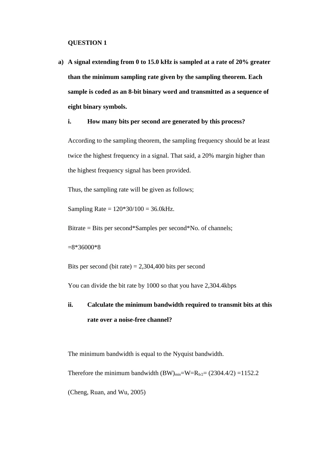
QUESTION 1
a) A signal extending from 0 to 15.0 kHz is sampled at a rate of 20% greater
than the minimum sampling rate given by the sampling theorem. Each
sample is coded as an 8-bit binary word and transmitted as a sequence of
eight binary symbols.
i. How many bits per second are generated by this process?
According to the sampling theorem, the sampling frequency should be at least
twice the highest frequency in a signal. That said, a 20% margin higher than
the highest frequency signal has been provided.
Thus, the sampling rate will be given as follows;
Sampling Rate = 120*30/100 = 36.0kHz.
Bitrate = Bits per second*Samples per second*No. of channels;
=8*36000*8
Bits per second (bit rate) = 2,304,400 bits per second
You can divide the bit rate by 1000 so that you have 2,304.4kbps
ii. Calculate the minimum bandwidth required to transmit bits at this
rate over a noise-free channel?
The minimum bandwidth is equal to the Nyquist bandwidth.
Therefore the minimum bandwidth (BW)min=W=Rb/2= (2304.4/2) =1152.2
(Cheng, Ruan, and Wu, 2005)
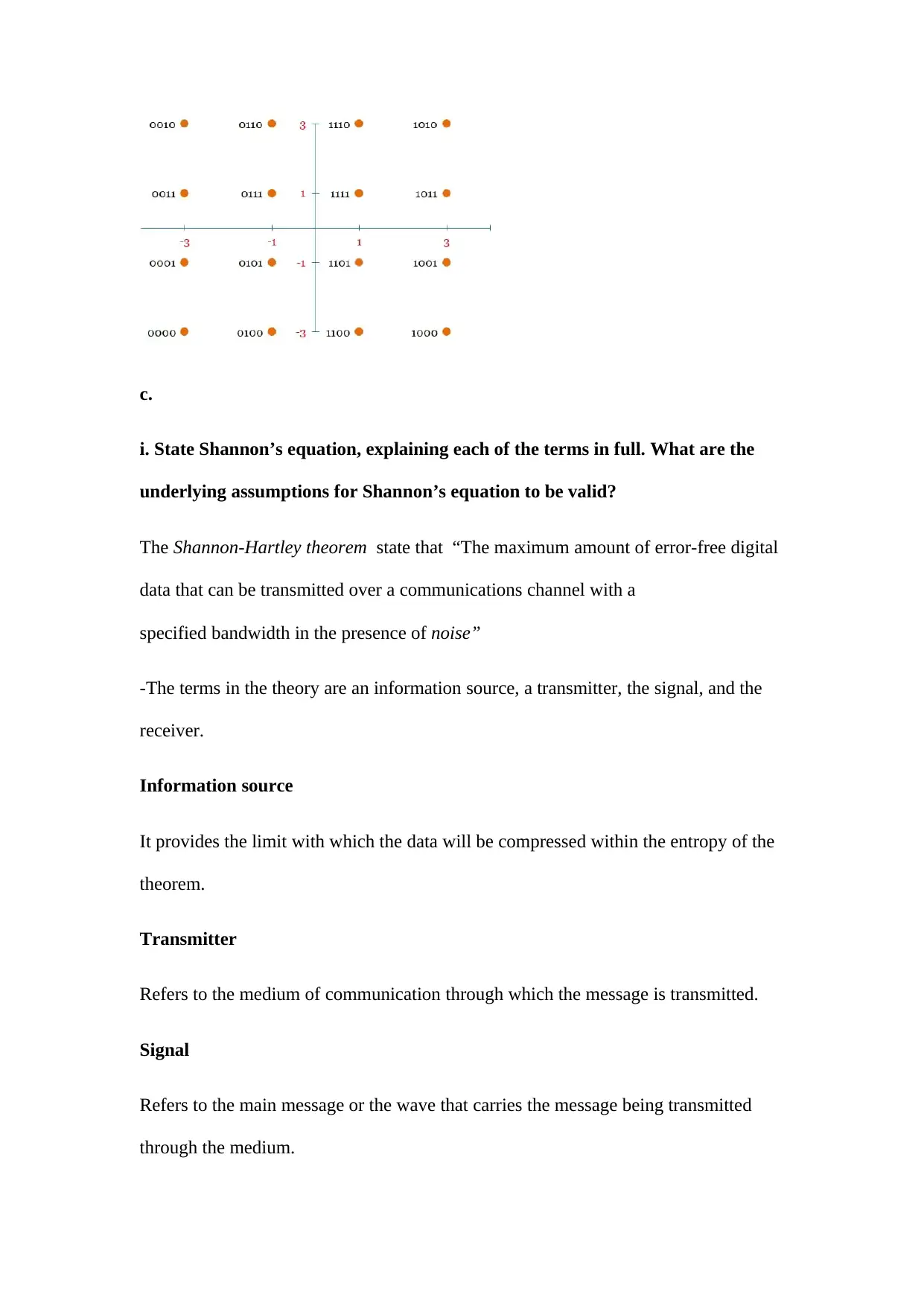
b. Sketch a signal constellation diagram for 16-QAM. Label the axes of
your diagram and explain what they stand for. State, with a brief explanation,
how many bits each point represents.
A rectangular QAM modulation is an equivalent of superimposing two ASK
signals on quadrature carriers. The size of each symbol is given by the formula
k=log2(M). Therefore, for a 16-QAM modulation:
k=log2(16) = 4
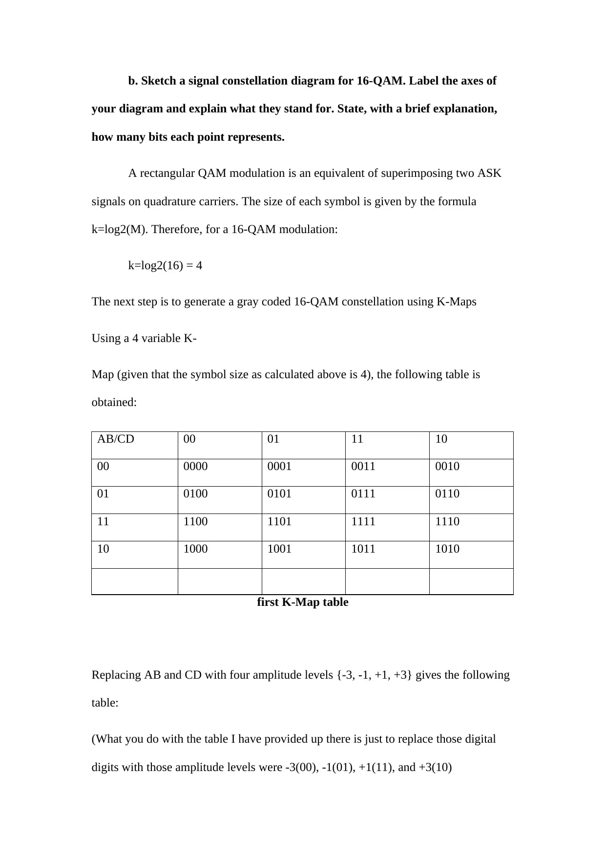
The next step is to generate a gray coded 16-QAM constellation using K-Maps
Using a 4 variable K-
Map (given that the symbol size as calculated above is 4), the following table is
obtained:
AB/CD 00 01 11 10
00 0000 0001 0011 0010
01 0100 0101 0111 0110
11 1100 1101 1111 1110
10 1000 1001 1011 1010
first K-Map table
Replacing AB and CD with four amplitude levels {-3, -1, +1, +3} gives the following
table:
(What you do with the table I have provided up there is just to replace those digital
digits with those amplitude levels were -3(00), -1(01), +1(11), and +3(10)
⊘ This is a preview!⊘
Do you want full access?
Subscribe today to unlock all pages.

Trusted by 1+ million students worldwide
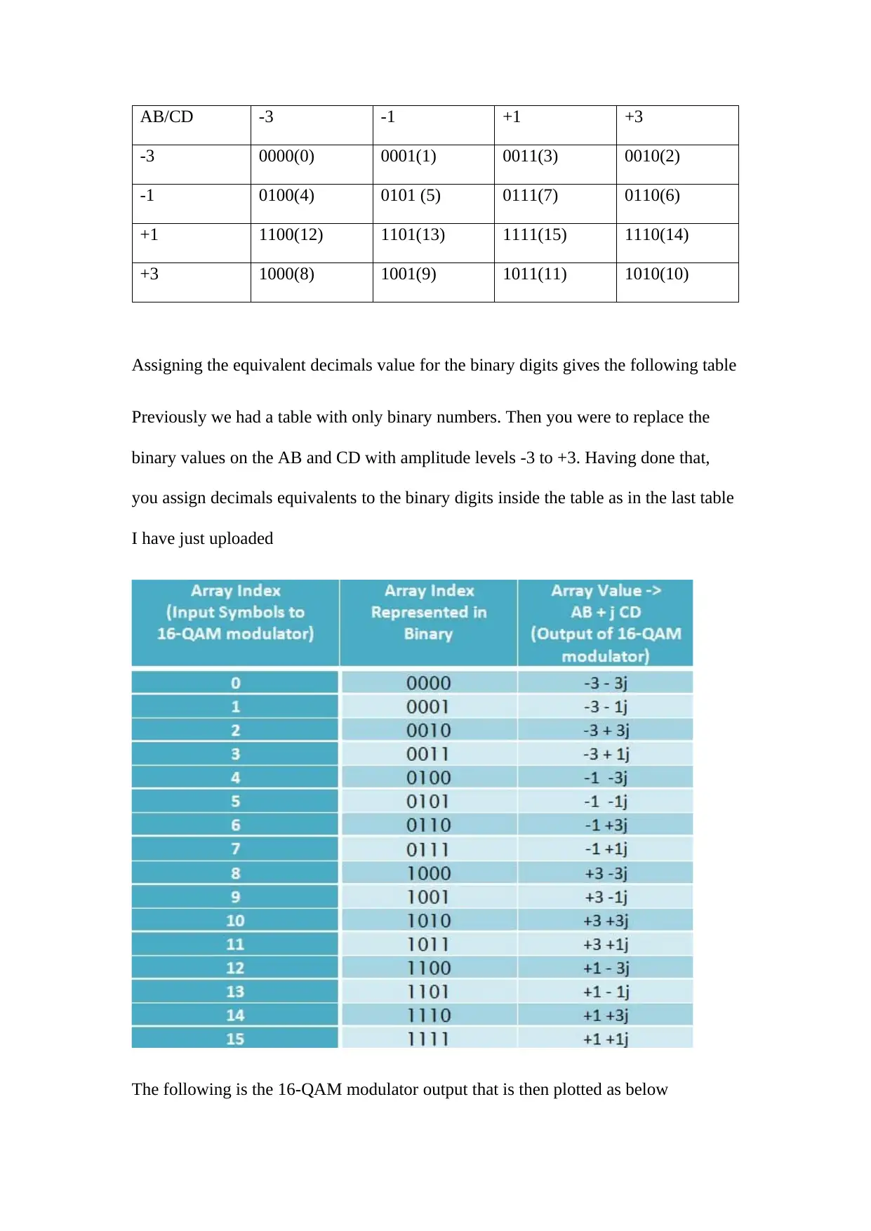
AB/CD -3 -1 +1 +3
-3 0000(0) 0001(1) 0011(3) 0010(2)
-1 0100(4) 0101 (5) 0111(7) 0110(6)
+1 1100(12) 1101(13) 1111(15) 1110(14)
+3 1000(8) 1001(9) 1011(11) 1010(10)
Assigning the equivalent decimals value for the binary digits gives the following table
Previously we had a table with only binary numbers. Then you were to replace the
binary values on the AB and CD with amplitude levels -3 to +3. Having done that,
you assign decimals equivalents to the binary digits inside the table as in the last table
I have just uploaded
The following is the 16-QAM modulator output that is then plotted as below
Paraphrase This Document
Need a fresh take? Get an instant paraphrase of this document with our AI Paraphraser
c.
i. State Shannon’s equation, explaining each of the terms in full. What are the
underlying assumptions for Shannon’s equation to be valid?
The Shannon-Hartley theorem state that “The maximum amount of error-free digital
data that can be transmitted over a communications channel with a
specified bandwidth in the presence of noise”
-The terms in the theory are an information source, a transmitter, the signal, and the
receiver.
Information source
It provides the limit with which the data will be compressed within the entropy of the
theorem.
Transmitter
Refers to the medium of communication through which the message is transmitted.
Signal
Refers to the main message or the wave that carries the message being transmitted
through the medium.
Receiver
It refers to the destination of the signal being transferred from the initial source of
information and from the transmitter.
Information source- it is basically where the coded information comes from
ii. Capacity
c= BW.log2(1+SNR)bps
c= 6.log2(1+SN36)
c= 6.log2(1+0.59)
c= 6.log2(1.59)
c= 6.log2(1.6)
c= 1.8(1.6)
c= 28.8
(Shannon, 1948)
Question 2
a. Refractive Index
It focuses on the relationship between the velocity of light traveling in a vacuum
and the velocity when it travels over some specified medium. In this case, it can be
⊘ This is a preview!⊘
Do you want full access?
Subscribe today to unlock all pages.

Trusted by 1+ million students worldwide
referred to the extent or the rate in which light is transmitted over some medium.
Since its normally greater compared to the cladding index, it causes refraction to
occur regularly over the transmission media, and at the interface incidences.
Therefore, it allows the attenuation of the light beam and reduces eliminates the
reflecting light over a given distance.
b. Multimode distortion
As the name suggests, it is a deformation that occurs through multiple modes,
which is caused by the difference in velocity of the optical signal being transmitted.
The distortion simply results from the delay caused by the rays traveling through the
optical fiber, where rays with shorter paths will be transmitted faster while those with
shorter paths will take longer. Besides, it occurs both at single and multiple
wavelengths, though it does not depend fully on them. The distortion poses several
effects the communication in that, it causes degradation of the transmitted signal and a
loss in the distribution.
c. Dispersion
It refers to the spread of rays traveling through an optical fiber. The wave tends to
broaden in the transmission process due to the effects of some features including the
diameter of the core and the width of the laser line. Hence, due to its increase with the
increase in distance traveled, it causes an effect known as the Intersymbol
Interference. The effect it has on the optical fiber communication is that it causes
overlapping of the pulses, making them less detectable.
d. Attenuation
It is a reduction in intensity experienced in a signal light that is being transmitted
through a fiber. The media components like connectors and cables play a major role
Paraphrase This Document
Need a fresh take? Get an instant paraphrase of this document with our AI Paraphraser

in its occurrence. Also, its happening involves both the single and multi-modes of
transmission. However, it can be overcome through the availing of sufficient light
within the data link to be used. It works to limit the long-distance transmission of the
digital signals.
transmission. However, it can be overcome through the availing of sufficient light
within the data link to be used. It works to limit the long-distance transmission of the
digital signals.
Question 3
a. Fourier Series and Fourier Transform
Fourier series refers to the application of sines and cosines whose sum exists in
an infinite form, in expanding a periodic function. It majorly applies the relationship
of the cosine and sine functions known as orthogonality. On the other hand, Fourier
transform refers to the generalized series of a complex Fourier, set on certain limits.
The only similarity that exists between the two is that both of them work on the
signals, irrespective of the activity occurring. Nonetheless, the first difference
between them is that Fourier series focuses on the actions of periodic signals, while
Fourier Transform targets the activities of the aperiodic signals. Secondly, Fourier
series is applied in the decomposition of signals to form the base elements while
Fourier transform is utilized in the analysis of signals in several domains (Duffin, and
Schaeffer, 1952)
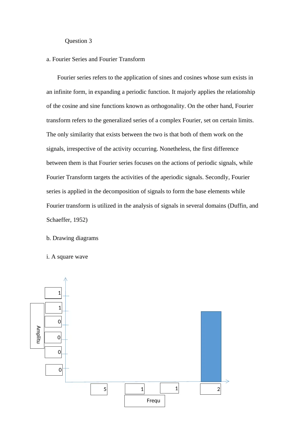
b. Drawing diagrams
i. A square wave
5
00
1 1 2
000
1
.2 1
.0 0
.8 0
.6 0
.4 0
.2
Amplitu
de (volts)
Frequ
ency (Hz)
⊘ This is a preview!⊘
Do you want full access?
Subscribe today to unlock all pages.

Trusted by 1+ million students worldwide

ii. A single rectangular pulse V
olts
m5-
2
olts
m5-
2
Paraphrase This Document
Need a fresh take? Get an instant paraphrase of this document with our AI Paraphraser
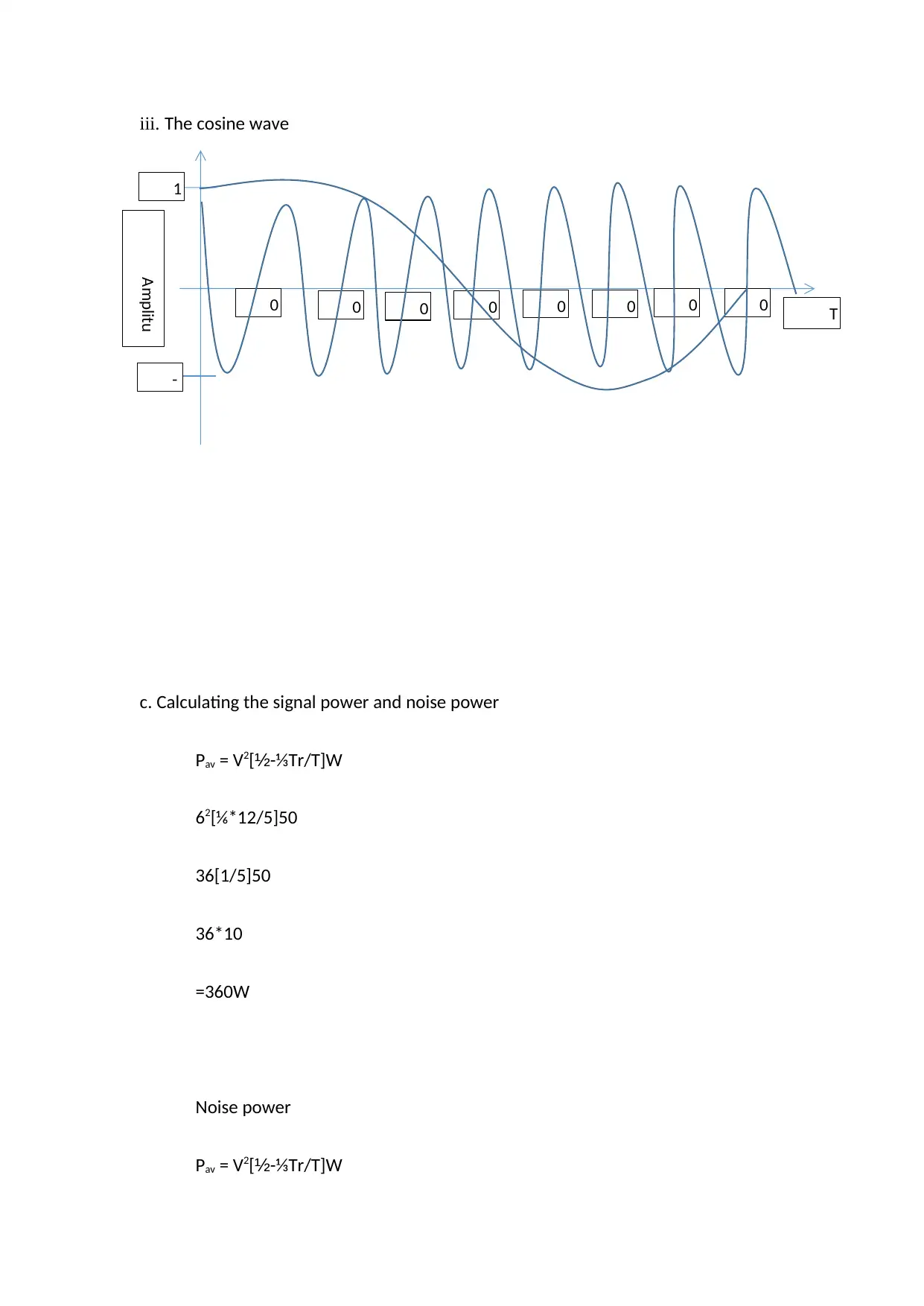
iii. The cosine wave
c. Calculating the signal power and noise power
Pav = V2[½-⅓Tr/T]W
62[⅙*12/5]50
36[1/5]50
36*10
=360W
Noise power
Pav = V2[½-⅓Tr/T]W
0 0 0 0 0 0 0 0
1
-
T
Amplitu
de (volts)
c. Calculating the signal power and noise power
Pav = V2[½-⅓Tr/T]W
62[⅙*12/5]50
36[1/5]50
36*10
=360W
Noise power
Pav = V2[½-⅓Tr/T]W
0 0 0 0 0 0 0 0
1
-
T
Amplitu
de (volts)
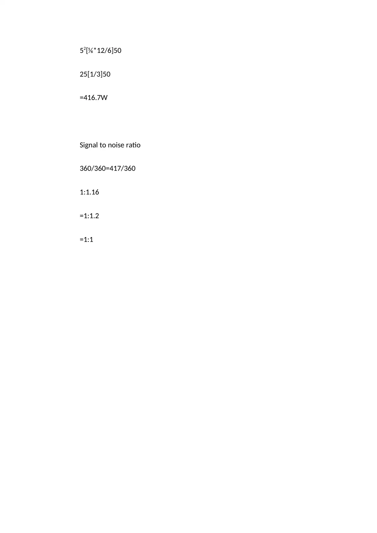
52[⅙*12/6]50
25[1/3]50
=416.7W
Signal to noise ratio
360/360=417/360
1:1.16
=1:1.2
=1:1
25[1/3]50
=416.7W
Signal to noise ratio
360/360=417/360
1:1.16
=1:1.2
=1:1
⊘ This is a preview!⊘
Do you want full access?
Subscribe today to unlock all pages.

Trusted by 1+ million students worldwide
1 out of 17
Related Documents
Your All-in-One AI-Powered Toolkit for Academic Success.
+13062052269
info@desklib.com
Available 24*7 on WhatsApp / Email
![[object Object]](/_next/static/media/star-bottom.7253800d.svg)
Unlock your academic potential
Copyright © 2020–2026 A2Z Services. All Rights Reserved. Developed and managed by ZUCOL.


