Torsional Buckling: Analysis, Concepts, and Factors in Beam Design
VerifiedAdded on 2023/06/04
|16
|3450
|209
Report
AI Summary
This report provides a comprehensive analysis of torsional buckling in beams, a critical structural phenomenon. It begins by defining buckling and its relevance to structural members, distinguishing between flexural, torsional, and flexural-torsional buckling. The report then delves into key concepts such as beam orientation, boundary conditions, cross-sections, center of gravity, shear center, center of twist, load application points, and warping. A significant portion of the report focuses on lateral torsional buckling, exploring its mechanism and the various factors that influence it, including load application point, end support conditions, bending moment distribution, lateral restraints, and cross-sectional shape. The report aims to provide a thorough understanding of torsional buckling and its implications in civil engineering design, highlighting the importance of considering these factors to prevent structural failure. The content is available on Desklib, a platform offering students past papers and solved assignments.
Running Head: TORSIONAL BUCKLING 1
Torsional Buckling of Beams Report
Student’s Name
Institutional Affiliation
Torsional Buckling of Beams Report
Student’s Name
Institutional Affiliation
Paraphrase This Document
Need a fresh take? Get an instant paraphrase of this document with our AI Paraphraser
Torsional Buckling 2
TABLE OF CONTENTS
ABSTRACT....................................................................................................................................3
1 INTRODUCTION...................................................................................................................4
2 DISCUSSION..........................................................................................................................5
2.1 Buckling............................................................................................................................5
2.2 Concepts............................................................................................................................7
2.2.1 Beam Orientation.......................................................................................................7
2.2.2 Boundary Conditions.................................................................................................8
2.2.3 Cross section..............................................................................................................8
2.2.4 Centre of gravity (COG)............................................................................................8
2.2.5 Shear Center (SC)......................................................................................................9
2.2.6 Center of Twist (COT)...............................................................................................9
2.2.7 Load Application Point..............................................................................................9
2.2.8 Warping...................................................................................................................10
2.3 Lateral Deflection...........................................................................................................10
2.4 Torsion............................................................................................................................11
2.5 Lateral Torsional Buckling.............................................................................................12
2.6 Mechanism of Lateral Torsional Buckling.....................................................................12
2.7 Factors affecting torsional buckling................................................................................12
2.7.1 Point of load application..........................................................................................12
2.7.2 Conditions of the end supports................................................................................13
2.7.3 Bending Moment Distribution.................................................................................13
2.7.4 Lateral restraints......................................................................................................13
2.7.5 Shape of Cross Section............................................................................................14
3 CONCLUSION......................................................................................................................14
REFERENCES..............................................................................................................................15
Torsional Buckling 3
ABSTRACT
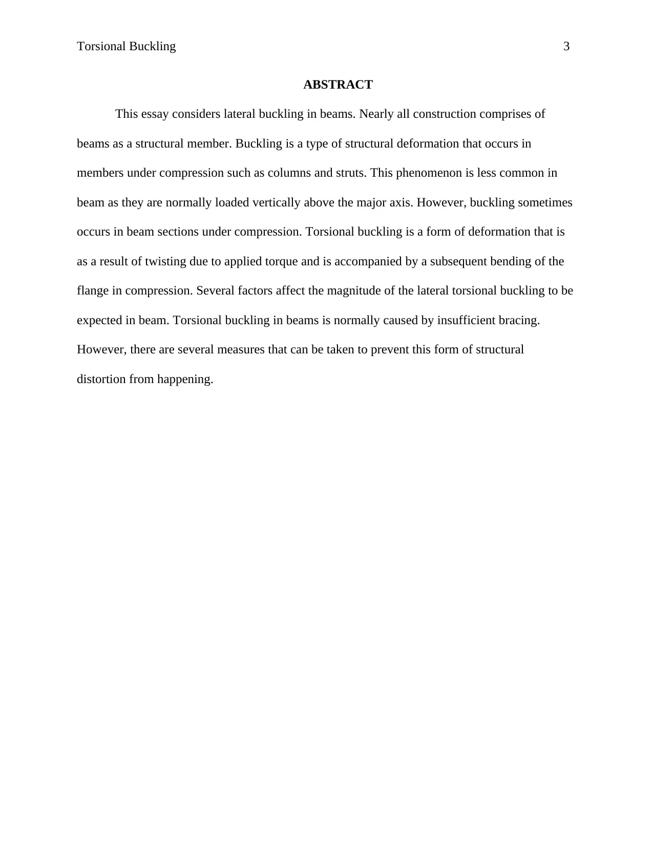
This essay considers lateral buckling in beams. Nearly all construction comprises of
beams as a structural member. Buckling is a type of structural deformation that occurs in
members under compression such as columns and struts. This phenomenon is less common in
beam as they are normally loaded vertically above the major axis. However, buckling sometimes
occurs in beam sections under compression. Torsional buckling is a form of deformation that is
as a result of twisting due to applied torque and is accompanied by a subsequent bending of the
flange in compression. Several factors affect the magnitude of the lateral torsional buckling to be
expected in beam. Torsional buckling in beams is normally caused by insufficient bracing.
However, there are several measures that can be taken to prevent this form of structural
distortion from happening.
ABSTRACT
This essay considers lateral buckling in beams. Nearly all construction comprises of
beams as a structural member. Buckling is a type of structural deformation that occurs in
members under compression such as columns and struts. This phenomenon is less common in
beam as they are normally loaded vertically above the major axis. However, buckling sometimes
occurs in beam sections under compression. Torsional buckling is a form of deformation that is
as a result of twisting due to applied torque and is accompanied by a subsequent bending of the
flange in compression. Several factors affect the magnitude of the lateral torsional buckling to be
expected in beam. Torsional buckling in beams is normally caused by insufficient bracing.
However, there are several measures that can be taken to prevent this form of structural
distortion from happening.
⊘ This is a preview!⊘
Do you want full access?
Subscribe today to unlock all pages.
Trusted by 1+ million students worldwide
Torsional Buckling 4
1 INTRODUCTION
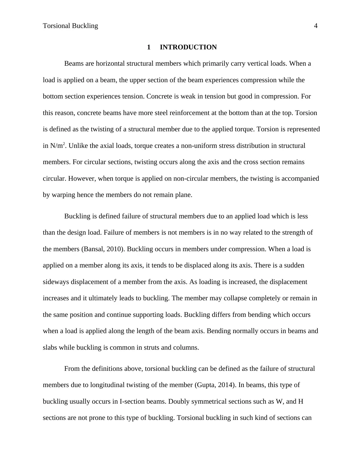
Beams are horizontal structural members which primarily carry vertical loads. When a
load is applied on a beam, the upper section of the beam experiences compression while the
bottom section experiences tension. Concrete is weak in tension but good in compression. For
this reason, concrete beams have more steel reinforcement at the bottom than at the top. Torsion
is defined as the twisting of a structural member due to the applied torque. Torsion is represented
in N/m2. Unlike the axial loads, torque creates a non-uniform stress distribution in structural
members. For circular sections, twisting occurs along the axis and the cross section remains
circular. However, when torque is applied on non-circular members, the twisting is accompanied
by warping hence the members do not remain plane.
Buckling is defined failure of structural members due to an applied load which is less
than the design load. Failure of members is not members is in no way related to the strength of
the members (Bansal, 2010). Buckling occurs in members under compression. When a load is
applied on a member along its axis, it tends to be displaced along its axis. There is a sudden
sideways displacement of a member from the axis. As loading is increased, the displacement
increases and it ultimately leads to buckling. The member may collapse completely or remain in
the same position and continue supporting loads. Buckling differs from bending which occurs
when a load is applied along the length of the beam axis. Bending normally occurs in beams and
slabs while buckling is common in struts and columns.
From the definitions above, torsional buckling can be defined as the failure of structural
members due to longitudinal twisting of the member (Gupta, 2014). In beams, this type of
buckling usually occurs in I-section beams. Doubly symmetrical sections such as W, and H
sections are not prone to this type of buckling. Torsional buckling in such kind of sections can
1 INTRODUCTION
Beams are horizontal structural members which primarily carry vertical loads. When a
load is applied on a beam, the upper section of the beam experiences compression while the
bottom section experiences tension. Concrete is weak in tension but good in compression. For
this reason, concrete beams have more steel reinforcement at the bottom than at the top. Torsion
is defined as the twisting of a structural member due to the applied torque. Torsion is represented
in N/m2. Unlike the axial loads, torque creates a non-uniform stress distribution in structural
members. For circular sections, twisting occurs along the axis and the cross section remains
circular. However, when torque is applied on non-circular members, the twisting is accompanied
by warping hence the members do not remain plane.
Buckling is defined failure of structural members due to an applied load which is less
than the design load. Failure of members is not members is in no way related to the strength of
the members (Bansal, 2010). Buckling occurs in members under compression. When a load is
applied on a member along its axis, it tends to be displaced along its axis. There is a sudden
sideways displacement of a member from the axis. As loading is increased, the displacement
increases and it ultimately leads to buckling. The member may collapse completely or remain in
the same position and continue supporting loads. Buckling differs from bending which occurs
when a load is applied along the length of the beam axis. Bending normally occurs in beams and
slabs while buckling is common in struts and columns.
From the definitions above, torsional buckling can be defined as the failure of structural
members due to longitudinal twisting of the member (Gupta, 2014). In beams, this type of
buckling usually occurs in I-section beams. Doubly symmetrical sections such as W, and H
sections are not prone to this type of buckling. Torsional buckling in such kind of sections can
Paraphrase This Document
Need a fresh take? Get an instant paraphrase of this document with our AI Paraphraser
Torsional Buckling 5
only occur if the torsional unbraced lengths are more than the flexural unbraced lengths (Gupta,
2014).
2 DISCUSSION
2.1 Buckling
Buckling is defined failure of structural members due to an applied load which is less
than the design load. Failure of members is not members is in no way related to the strength of
the members. Buckling occurs in members under compression. When a load is applied on a
member along its axis, it tends to be displaced along its axis. There is a sudden sideways
displacement of a member from the axis. As loading is increased, the displacement increases and
it ultimately leads to buckling. The member may collapse completely or remain in the same
position and continue supporting loads.
Slenderness ratio is used to determine if a member is susceptible to buckling. Slenderness
ratio is defined as the ratio between the effective length of the structural member and the radius
of gyration of the member’s cross section.
S= Le
r
r = √ I
A
Where, S = Slenderness ratio
Le= effective length
r = radius of gyration
I = Moment of Inertia
Torsional Buckling 6
A = Cross sectional Area
A member with a high slenderness ratio is prone to buckling while that with small slenderness
ratio is less susceptible for buckling.
Steel columns are considered to be linear members because the cross-sectional
dimensions are smaller compared to their lengths. This implies that columns are more susceptible
to fail due to buckling rather than yielding. There are two forms of failure for members under
compression.
1. Local instability- This occurs where parts of the members are relatively thin resulting
in localized buckling. The sections can be determined to be slender or not based on
the formulas provided above.
2. Overall Instability- This type of phenomenon occurs when the whole member
experiences buckling throughout its length leading to bending of the section from its
axis. This type of buckling can occur in various ways:
Flexural buckling- deformation occurs through bending about the weaker axis.
Flexural buckling in steel can be either elastic or inelastic depending on the
stress levels experienced before buckling compared with the steel stress limit
(Kindmann & Kraus, 2012).
Torsional buckling- In this type of buckling, the member twists along its axis.
Common in I-section beams. Doubly symmetrical sections such as W, and H
sections are not prone to this type of buckling. Torsional buckling in such kind
of sections can only occur if the torsional unbraced lengths are more than the
flexural unbraced lengths (Gupta, 2014).
⊘ This is a preview!⊘
Do you want full access?
Subscribe today to unlock all pages.
Trusted by 1+ million students worldwide
Torsional Buckling 7
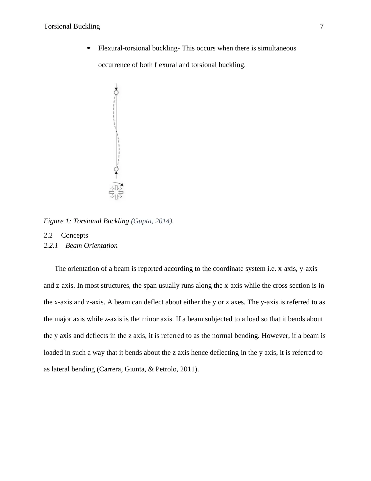
Flexural-torsional buckling- This occurs when there is simultaneous
occurrence of both flexural and torsional buckling.
Figure 1: Torsional Buckling (Gupta, 2014).
2.2 Concepts
2.2.1 Beam Orientation
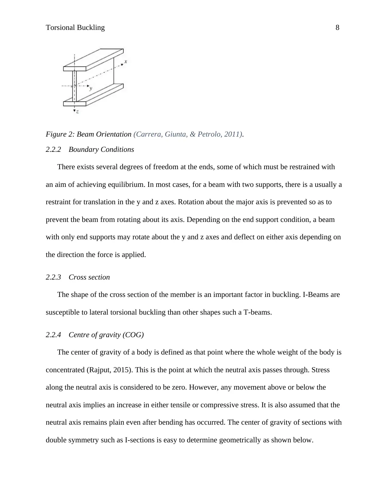
The orientation of a beam is reported according to the coordinate system i.e. x-axis, y-axis
and z-axis. In most structures, the span usually runs along the x-axis while the cross section is in
the x-axis and z-axis. A beam can deflect about either the y or z axes. The y-axis is referred to as
the major axis while z-axis is the minor axis. If a beam subjected to a load so that it bends about
the y axis and deflects in the z axis, it is referred to as the normal bending. However, if a beam is
loaded in such a way that it bends about the z axis hence deflecting in the y axis, it is referred to
as lateral bending (Carrera, Giunta, & Petrolo, 2011).
Flexural-torsional buckling- This occurs when there is simultaneous
occurrence of both flexural and torsional buckling.
Figure 1: Torsional Buckling (Gupta, 2014).
2.2 Concepts
2.2.1 Beam Orientation
The orientation of a beam is reported according to the coordinate system i.e. x-axis, y-axis
and z-axis. In most structures, the span usually runs along the x-axis while the cross section is in
the x-axis and z-axis. A beam can deflect about either the y or z axes. The y-axis is referred to as
the major axis while z-axis is the minor axis. If a beam subjected to a load so that it bends about
the y axis and deflects in the z axis, it is referred to as the normal bending. However, if a beam is
loaded in such a way that it bends about the z axis hence deflecting in the y axis, it is referred to
as lateral bending (Carrera, Giunta, & Petrolo, 2011).
Paraphrase This Document
Need a fresh take? Get an instant paraphrase of this document with our AI Paraphraser
Torsional Buckling 8
Figure 2: Beam Orientation (Carrera, Giunta, & Petrolo, 2011).
2.2.2 Boundary Conditions
There exists several degrees of freedom at the ends, some of which must be restrained with
an aim of achieving equilibrium. In most cases, for a beam with two supports, there is a usually a
restraint for translation in the y and z axes. Rotation about the major axis is prevented so as to
prevent the beam from rotating about its axis. Depending on the end support condition, a beam
with only end supports may rotate about the y and z axes and deflect on either axis depending on
the direction the force is applied.
2.2.3 Cross section
The shape of the cross section of the member is an important factor in buckling. I-Beams are
susceptible to lateral torsional buckling than other shapes such a T-beams.
2.2.4 Centre of gravity (COG)
The center of gravity of a body is defined as that point where the whole weight of the body is
concentrated (Rajput, 2015). This is the point at which the neutral axis passes through. Stress
along the neutral axis is considered to be zero. However, any movement above or below the
neutral axis implies an increase in either tensile or compressive stress. It is also assumed that the
neutral axis remains plain even after bending has occurred. The center of gravity of sections with
double symmetry such as I-sections is easy to determine geometrically as shown below.
Torsional Buckling 9
2.2.5 Shear Center (SC)
Shear center is defined as the point at which the shear force acts so as to only cause in-plane
bending (Megson, 2013). The shear center of sections with double symmetry such as I-sections is
easy to determine geometrically as shown below. For this type of sections, the COG coincides
with the shear center.
2.2.6 Center of Twist (COT)
The COT of a body is the point along which the twisting axis will pass through. Twisting will
happen about this point (Barretta, 2012). Usually, though with different definitions, both the
shear center and center of twist always coincide. Therefore, for a section with double symmetry,
the center of twist, center of gravity and shear center will always coincide. In our case, this will
apply since we shall be considering an I-section with double symmetry i.e. symmetrical in both
the x and y axis.
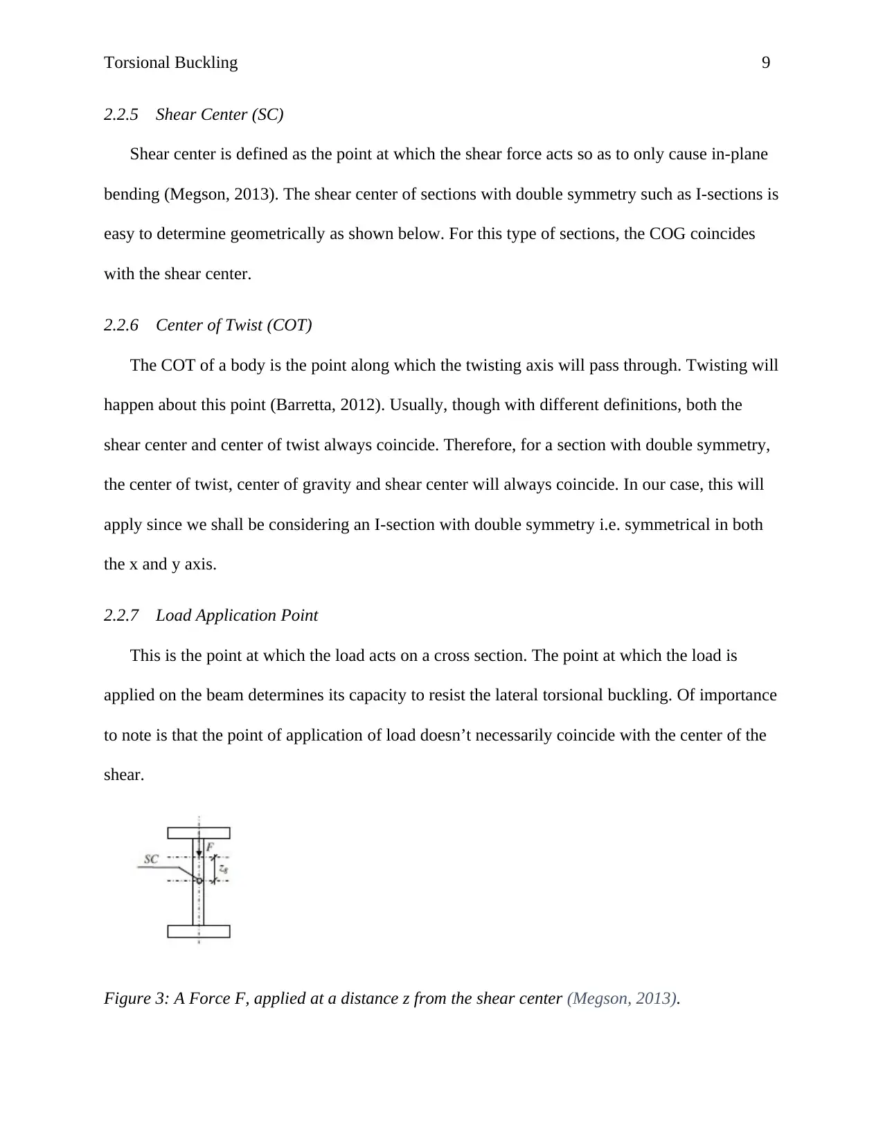
2.2.7 Load Application Point
This is the point at which the load acts on a cross section. The point at which the load is
applied on the beam determines its capacity to resist the lateral torsional buckling. Of importance
to note is that the point of application of load doesn’t necessarily coincide with the center of the
shear.
Figure 3: A Force F, applied at a distance z from the shear center (Megson, 2013).
2.2.5 Shear Center (SC)
Shear center is defined as the point at which the shear force acts so as to only cause in-plane
bending (Megson, 2013). The shear center of sections with double symmetry such as I-sections is
easy to determine geometrically as shown below. For this type of sections, the COG coincides
with the shear center.
2.2.6 Center of Twist (COT)
The COT of a body is the point along which the twisting axis will pass through. Twisting will
happen about this point (Barretta, 2012). Usually, though with different definitions, both the
shear center and center of twist always coincide. Therefore, for a section with double symmetry,
the center of twist, center of gravity and shear center will always coincide. In our case, this will
apply since we shall be considering an I-section with double symmetry i.e. symmetrical in both
the x and y axis.
2.2.7 Load Application Point
This is the point at which the load acts on a cross section. The point at which the load is
applied on the beam determines its capacity to resist the lateral torsional buckling. Of importance
to note is that the point of application of load doesn’t necessarily coincide with the center of the
shear.
Figure 3: A Force F, applied at a distance z from the shear center (Megson, 2013).
⊘ This is a preview!⊘
Do you want full access?
Subscribe today to unlock all pages.
Trusted by 1+ million students worldwide
Torsional Buckling 10
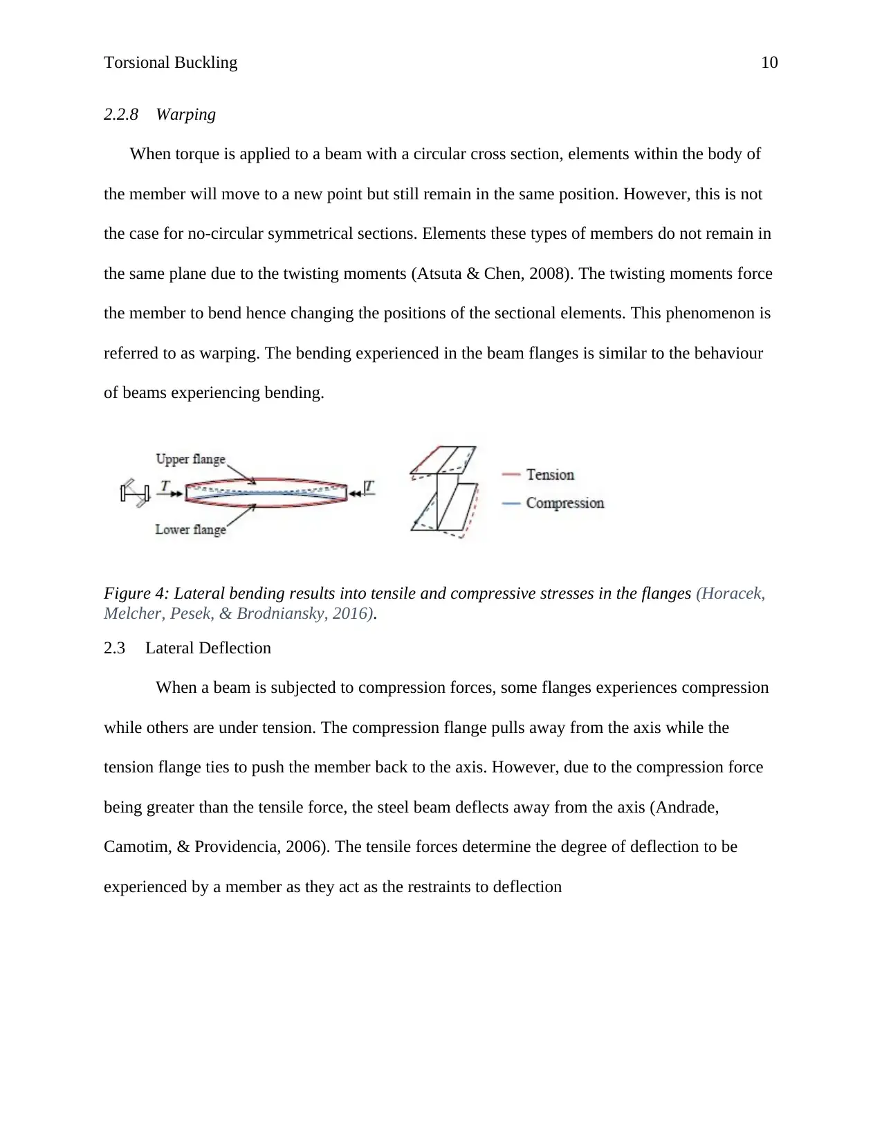
2.2.8 Warping
When torque is applied to a beam with a circular cross section, elements within the body of
the member will move to a new point but still remain in the same position. However, this is not
the case for no-circular symmetrical sections. Elements these types of members do not remain in
the same plane due to the twisting moments (Atsuta & Chen, 2008). The twisting moments force
the member to bend hence changing the positions of the sectional elements. This phenomenon is
referred to as warping. The bending experienced in the beam flanges is similar to the behaviour
of beams experiencing bending.
Figure 4: Lateral bending results into tensile and compressive stresses in the flanges (Horacek,
Melcher, Pesek, & Brodniansky, 2016).
2.3 Lateral Deflection
When a beam is subjected to compression forces, some flanges experiences compression
while others are under tension. The compression flange pulls away from the axis while the
tension flange ties to push the member back to the axis. However, due to the compression force
being greater than the tensile force, the steel beam deflects away from the axis (Andrade,
Camotim, & Providencia, 2006). The tensile forces determine the degree of deflection to be
experienced by a member as they act as the restraints to deflection
Paraphrase This Document
Need a fresh take? Get an instant paraphrase of this document with our AI Paraphraser
Torsional Buckling 11
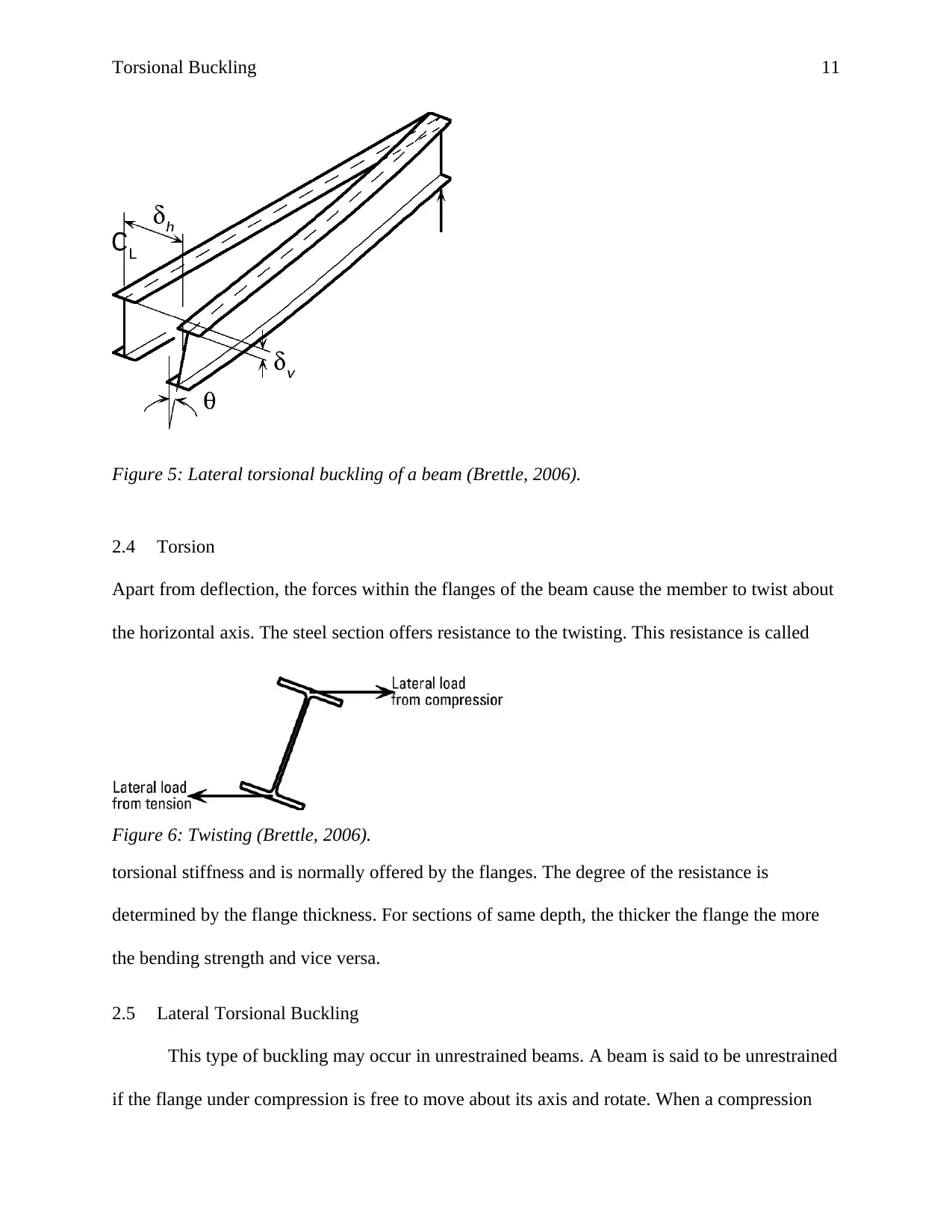
Figure 5: Lateral torsional buckling of a beam (Brettle, 2006).
2.4 Torsion
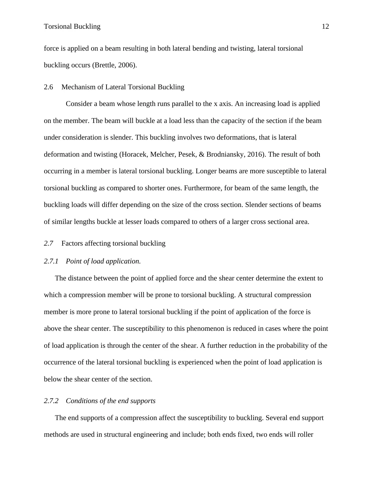
Apart from deflection, the forces within the flanges of the beam cause the member to twist about
the horizontal axis. The steel section offers resistance to the twisting. This resistance is called
Figure 6: Twisting (Brettle, 2006).
torsional stiffness and is normally offered by the flanges. The degree of the resistance is
determined by the flange thickness. For sections of same depth, the thicker the flange the more
the bending strength and vice versa.
2.5 Lateral Torsional Buckling
This type of buckling may occur in unrestrained beams. A beam is said to be unrestrained
if the flange under compression is free to move about its axis and rotate. When a compression
Figure 5: Lateral torsional buckling of a beam (Brettle, 2006).
2.4 Torsion
Apart from deflection, the forces within the flanges of the beam cause the member to twist about
the horizontal axis. The steel section offers resistance to the twisting. This resistance is called
Figure 6: Twisting (Brettle, 2006).
torsional stiffness and is normally offered by the flanges. The degree of the resistance is
determined by the flange thickness. For sections of same depth, the thicker the flange the more
the bending strength and vice versa.
2.5 Lateral Torsional Buckling
This type of buckling may occur in unrestrained beams. A beam is said to be unrestrained
if the flange under compression is free to move about its axis and rotate. When a compression
Torsional Buckling 12
force is applied on a beam resulting in both lateral bending and twisting, lateral torsional
buckling occurs (Brettle, 2006).
2.6 Mechanism of Lateral Torsional Buckling
Consider a beam whose length runs parallel to the x axis. An increasing load is applied
on the member. The beam will buckle at a load less than the capacity of the section if the beam
under consideration is slender. This buckling involves two deformations, that is lateral
deformation and twisting (Horacek, Melcher, Pesek, & Brodniansky, 2016). The result of both
occurring in a member is lateral torsional buckling. Longer beams are more susceptible to lateral
torsional buckling as compared to shorter ones. Furthermore, for beam of the same length, the
buckling loads will differ depending on the size of the cross section. Slender sections of beams
of similar lengths buckle at lesser loads compared to others of a larger cross sectional area.
2.7 Factors affecting torsional buckling
2.7.1 Point of load application.
The distance between the point of applied force and the shear center determine the extent to
which a compression member will be prone to torsional buckling. A structural compression
member is more prone to lateral torsional buckling if the point of application of the force is
above the shear center. The susceptibility to this phenomenon is reduced in cases where the point
of load application is through the center of the shear. A further reduction in the probability of the
occurrence of the lateral torsional buckling is experienced when the point of load application is
below the shear center of the section.
2.7.2 Conditions of the end supports
The end supports of a compression affect the susceptibility to buckling. Several end support
methods are used in structural engineering and include; both ends fixed, two ends will roller
⊘ This is a preview!⊘
Do you want full access?
Subscribe today to unlock all pages.
Trusted by 1+ million students worldwide
1 out of 16
Related Documents


Your All-in-One AI-Powered Toolkit for Academic Success.
+13062052269
info@desklib.com
Available 24*7 on WhatsApp / Email
![[object Object]](/_next/static/media/star-bottom.7253800d.svg)
Unlock your academic potential
Copyright © 2020–2026 A2Z Services. All Rights Reserved. Developed and managed by ZUCOL.