Report on Torsional Buckling of Beams: Analysis and Examples
VerifiedAdded on 2020/05/11
|12
|2391
|206
Report
AI Summary
This report investigates the phenomenon of torsional buckling in beams, a critical consideration in structural engineering. It begins by defining torsional buckling and explaining its occurrence in unstrained beams under compression, emphasizing the role of lateral displacement and twisting. The report then delves into the reasons behind torsional buckling, highlighting the influence of flange thickness, load application points, and shear centers. It discusses the importance of end support conditions and effective lengths in determining buckling moments. Furthermore, the report provides examples of constructions susceptible to torsional buckling, such as steel-concrete composite buildings, and illustrates the application of finite element analysis in understanding and mitigating this issue. The conclusion summarizes key findings and the significance of this analysis in structural design. References include various research papers and studies on the topic.
torsional buckling of beams
LENOVO
[Company name] [Company address]
LENOVO
[Company name] [Company address]
Paraphrase This Document
Need a fresh take? Get an instant paraphrase of this document with our AI Paraphraser
Contents
Introduction......................................................................................................................................1
Reasons behind torsional buckling of beams...................................................................................2
Examples of constructions with the torsional buckling of beams...................................................5
Conclusion.......................................................................................................................................7
References........................................................................................................................................8
Introduction
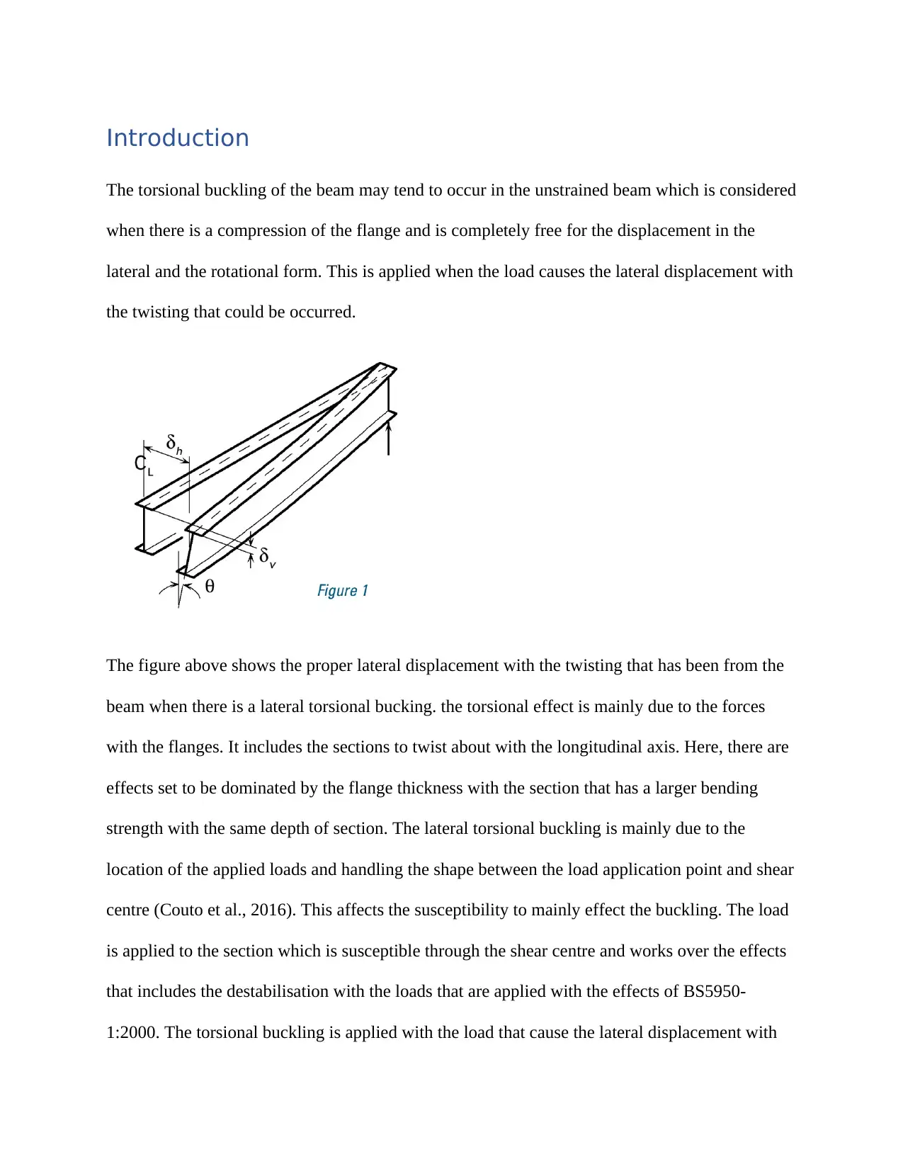
The torsional buckling of the beam may tend to occur in the unstrained beam which is considered
when there is a compression of the flange and is completely free for the displacement in the
lateral and the rotational form. This is applied when the load causes the lateral displacement with
the twisting that could be occurred.
The figure above shows the proper lateral displacement with the twisting that has been from the
beam when there is a lateral torsional bucking. the torsional effect is mainly due to the forces
with the flanges. It includes the sections to twist about with the longitudinal axis. Here, there are
effects set to be dominated by the flange thickness with the section that has a larger bending
strength with the same depth of section. The lateral torsional buckling is mainly due to the
location of the applied loads and handling the shape between the load application point and shear
centre (Couto et al., 2016). This affects the susceptibility to mainly effect the buckling. The load
is applied to the section which is susceptible through the shear centre and works over the effects
that includes the destabilisation with the loads that are applied with the effects of BS5950-
1:2000. The torsional buckling is applied with the load that cause the lateral displacement with
⊘ This is a preview!⊘
Do you want full access?
Subscribe today to unlock all pages.
Trusted by 1+ million students worldwide
the twisting. The failure is when the load is applied to the unconstrained steam with the flanges
that have been acting under the compression and one under the tension. The unconstrainted are
mainly due to the compression which is free for moving laterally and has a twist as well.
Reasons behind torsional buckling of beams
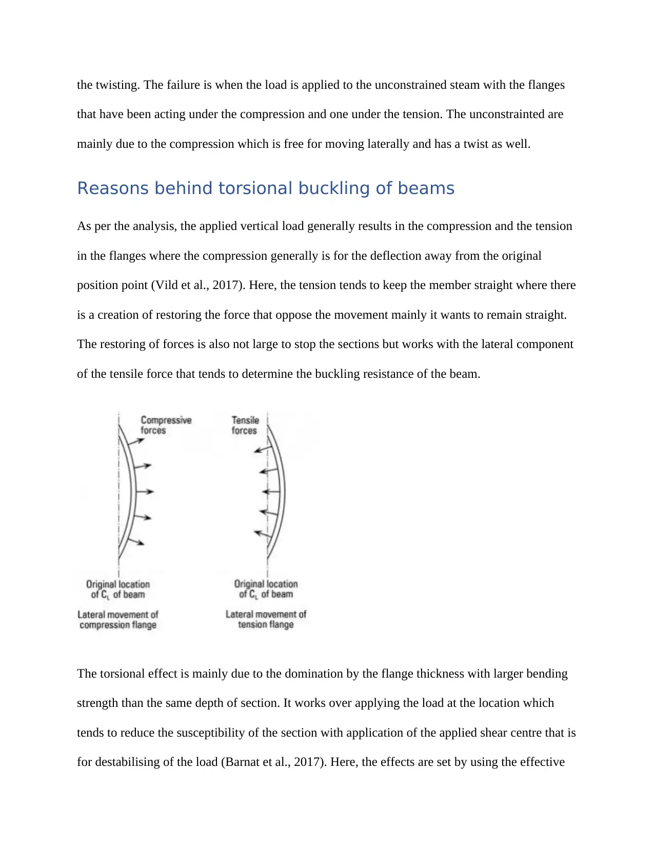
As per the analysis, the applied vertical load generally results in the compression and the tension
in the flanges where the compression generally is for the deflection away from the original
position point (Vild et al., 2017). Here, the tension tends to keep the member straight where there
is a creation of restoring the force that oppose the movement mainly it wants to remain straight.
The restoring of forces is also not large to stop the sections but works with the lateral component
of the tensile force that tends to determine the buckling resistance of the beam.
The torsional effect is mainly due to the domination by the flange thickness with larger bending
strength than the same depth of section. It works over applying the load at the location which
tends to reduce the susceptibility of the section with application of the applied shear centre that is
for destabilising of the load (Barnat et al., 2017). Here, the effects are set by using the effective
that have been acting under the compression and one under the tension. The unconstrainted are
mainly due to the compression which is free for moving laterally and has a twist as well.
Reasons behind torsional buckling of beams
As per the analysis, the applied vertical load generally results in the compression and the tension
in the flanges where the compression generally is for the deflection away from the original
position point (Vild et al., 2017). Here, the tension tends to keep the member straight where there
is a creation of restoring the force that oppose the movement mainly it wants to remain straight.
The restoring of forces is also not large to stop the sections but works with the lateral component
of the tensile force that tends to determine the buckling resistance of the beam.
The torsional effect is mainly due to the domination by the flange thickness with larger bending
strength than the same depth of section. It works over applying the load at the location which
tends to reduce the susceptibility of the section with application of the applied shear centre that is
for destabilising of the load (Barnat et al., 2017). Here, the effects are set by using the effective
Paraphrase This Document
Need a fresh take? Get an instant paraphrase of this document with our AI Paraphraser
lengths and working over the uniform distribution along its length. There are factors which
include the design with the guidance to allow the effect of different bending moment
distributions. They are familiar to make use of the uniform moment factor.
The end support conditions are considered important for the development for the buckling
moments where the web cleats tend to stop the web from deflection in the lateral form. The end
conditions are where there are more restraints which are set for the increased buckling moment,
with the end support that offer less restraints. The effective length is to determine the slenderness
of the section which accounts to the effect of end restraint on the lateral torsional buckling.
The slenderness of the section has been important for the designing check for the lateral torsional
buckling where the factors that affect are:
a. The beam length
b. The stiffness of the lateral bending of the flanges
c. The handling of the stiffness of the torsional section (Mandal et al., 2002).
Here, the designing codes are important to focus on determining the section slenderness with the
elastic critical moment that is for the methods set for determining the Euler buckling of a strut.
This works over the defined forms of the axial compression that will lead to the failure of the
elastic flexural buckling that is compared to the critical moment with properly defining the
moment which results in the failure mainly due to the elastic lateral torsional buckling of beam.
Here, the sections are set to define about the varying slender sections which tend to fail
elastically with the excessive lateral torsional buckling which is then applied for the moment
(Horacek et al, 2017). The intermediate slender sections tend to fail in elastically by the
excessive forms of the lateral torsions where the stocky sections attain the plastic moment with
the negligible lateral torsional buckling. The focus of the research is about the instability which
is based on testing the real beams. Here, the methods are time consuming and could leave room
for the errors. The modelling like the beam is easy for the computer based techniques, where the
performance is set to argue about the different forms under the elastic conditions with the
geometry and no initial imperfections. There are no beams which are perfect and tend to behave
completely different from the ideal ones (Naaim et al, 2016). It is important to focus on the
energy methods which could be for handling the specific load cases where the total potential of
the system is to minimise the state of equilibrium and work over the states that could adjust to a
deflected shape to the lowest potential energy as well. The critical loading is where there is no
energy which is needed for the deformation of the beam into the adjustment to the deflected
shape which corresponds to the lowest potential energy. Here, there is no major need to deform a
beam which has been deflected with the state of equilibrium where the potential also does not
tend to change. There is a need to focus on the work load by the external loading at the time of
buckling which is same to the internal work done by the sectional forces. Here, the focus is on
the mechanisms which are complex, and which makes the evaluation difficult for the elastic
critical moment (Qiao et al., 2003). The 3-factor formula includes the different variables that has
a major issue with the variables with analytical approach. Here, the focus is on handling the no
exact closed form expression where the structural patterns depends on the moment forms. The
approximate value is depending upon the validation with the detailed analysis of the incremental
forms. The value of the distributed loads takes hold of the acts that have the shear centre rather
than the flanges. To work on the programs, there is a need to make use of the establishing of
finite element model which could be a part of the lateral boundary conditions with the real beam
connections that are properly modelled and evaluated (Valarinho et al., 2016). Here, the different
⊘ This is a preview!⊘
Do you want full access?
Subscribe today to unlock all pages.
Trusted by 1+ million students worldwide
standards are set for the critical moment with the 3 factor standards to focus over the
continuation and work over the designing procedures which are set regarding the lateral torsional
buckling. The forms are set with the magnitude of errors which have been introduced by the
buckling curves.
Examples of constructions with the torsional buckling of
beams
Some of the examples which are related to the buckling of the beams is accounted for the
construction where there is construction of the steel-concrete composite buildings, with the
steam beams that are designed for the full moment capacity based on the flooring which also
provide the lateral restraints to the beams. The erection stage of the structure with the beams that
does not receive he lateral support from the floors have the concrete hardening. The stages are
generally prone to the lateral buckling where the rolled sections are set invariably with the
reduced residual stress. Here, the effects of deviation with the example of New IS 800 considers
any of the destabilising effects with the top flange loading set using the notional effective length
span (Plaut et al., 2017).
Paraphrase This Document
Need a fresh take? Get an instant paraphrase of this document with our AI Paraphraser
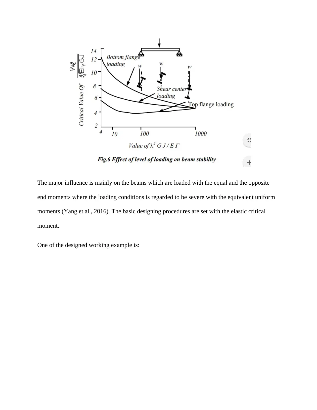
The major influence is mainly on the beams which are loaded with the equal and the opposite
end moments where the loading conditions is regarded to be severe with the equivalent uniform
moments (Yang et al., 2016). The basic designing procedures are set with the elastic critical
moment.
One of the designed working example is:
end moments where the loading conditions is regarded to be severe with the equivalent uniform
moments (Yang et al., 2016). The basic designing procedures are set with the elastic critical
moment.
One of the designed working example is:
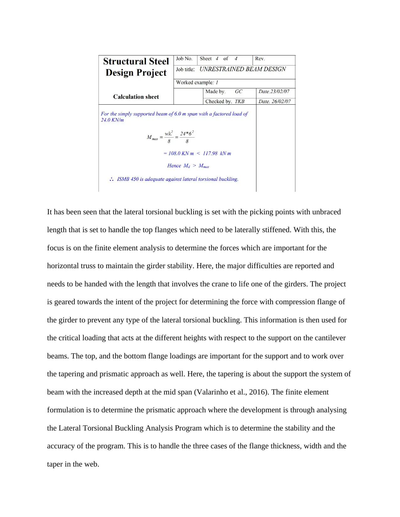
It has been seen that the lateral torsional buckling is set with the picking points with unbraced
length that is set to handle the top flanges which need to be laterally stiffened. With this, the
focus is on the finite element analysis to determine the forces which are important for the
horizontal truss to maintain the girder stability. Here, the major difficulties are reported and
needs to be handed with the length that involves the crane to life one of the girders. The project
is geared towards the intent of the project for determining the force with compression flange of
the girder to prevent any type of the lateral torsional buckling. This information is then used for
the critical loading that acts at the different heights with respect to the support on the cantilever
beams. The top, and the bottom flange loadings are important for the support and to work over
the tapering and prismatic approach as well. Here, the tapering is about the support the system of
beam with the increased depth at the mid span (Valarinho et al., 2016). The finite element
formulation is to determine the prismatic approach where the development is through analysing
the Lateral Torsional Buckling Analysis Program which is to determine the stability and the
accuracy of the program. This is to handle the three cases of the flange thickness, width and the
taper in the web.
⊘ This is a preview!⊘
Do you want full access?
Subscribe today to unlock all pages.
Trusted by 1+ million students worldwide
Conclusion
As per the study, there are reasons and the expressions which could lead to the study and work
over the calculation of the old element formulation. This is mainly used for the boundary
conditions and to work over the validity and reliability of results. The reference values are
related to the validation sections for the beam lengths and to handle the parametric study as well.
The results are when there are no lateral restraints but have the common closed form expressions
which takes into account all the base load effects with the buckling analysis.
Paraphrase This Document
Need a fresh take? Get an instant paraphrase of this document with our AI Paraphraser
References
Barnat, J., Bajer, M., Vild, M., Melcher, J., Karmazínová, M., & Piják, J. (2017). Experimental Analysis of
Lateral Torsional Buckling of Beams with Selected Cross-Section Types. Procedia
Engineering, 195, 56-61.
Couto, C., Real, P. V., Lopes, N., & Zhao, B. (2016). Numerical investigation of the lateral–torsional
buckling of beams with slender cross sections for the case of fire. Engineering Structures, 106,
410-421.
Horáček, M., & Melcher, J. (2017). Lateral‐torsional buckling of beams of double symmetrical and mono‐
symmetrical cross‐sections loaded perpendicularly to the axis of symmetry: Experimental
verification. ce/papers, 1(2-3), 1417-1426.
Mandal, P., & Calladine, C. R. (2002). Lateral-torsional buckling of beams and the Southwell
plot. International Journal of Mechanical Sciences, 44(12), 2557-2571.
Naaim, N., De'nan, F., Keong, C. K., & Azar, F. (2016). Finite Element Analysis of Lateral Torsional
Buckling Behaviour of Tapered Steel Section with Perforation. In MATEC Web of
Conferences (Vol. 47). EDP Sciences.
Plaut, R. H., & Eatherton, M. R. (2017). Lateral-torsional buckling of butterfly-shaped beams with
rectangular cross section. Engineering Structures, 136, 210-218.
Qiao, P., Zou, G., & Davalos, J. F. (2003). Flexural–torsional buckling of fiber-reinforced plastic composite
cantilever I-beams. Composite Structures, 60(2), 205-217.
Valarinho, L., Correia, J. R., Machado-e-Costa, M., Branco, F. A., & Silvestre, N. (2016). Lateral-torsional
buckling behaviour of long-span laminated glass beams: Analytical, experimental and numerical
study. Materials & Design, 102, 264-275.
Valarinho, L., Correia, J. R., Machado-e-Costa, M., Branco, F. A., & Silvestre, N. (2016). Corrigendum to
“Lateral-torsional buckling behaviour of long-span laminated glass beams: Analytical,
experimental and numerical study”[Materials & Design, volume 102, 15 July 2016, pages 264–
275]. Materials & Design, (107), 371.
Vild, M., Piják, J., Barnat, J., Bajer, M., Melcher, J., & Karmazínová, M. (2017). Comparison of analytical
and numerical methods applied to lateral torsional buckling of beams. Procedia Engineering, 195,
48-55.
Yang, B., Xiong, G., Ding, K., Nie, S., Zhang, W., Hu, Y., & Dai, G. (2016). Experimental and numerical
studies on lateral-torsional buckling of GJ structural steel beams under a concentrated loading
condition. International Journal of Structural Stability and Dynamics, 16(01), 1640004.
⊘ This is a preview!⊘
Do you want full access?
Subscribe today to unlock all pages.
Trusted by 1+ million students worldwide
1 out of 12
Related Documents


Your All-in-One AI-Powered Toolkit for Academic Success.
+13062052269
info@desklib.com
Available 24*7 on WhatsApp / Email
![[object Object]](/_next/static/media/star-bottom.7253800d.svg)
Unlock your academic potential
Copyright © 2020–2026 A2Z Services. All Rights Reserved. Developed and managed by ZUCOL.