Analysis and Design: Modeling Wide World Tour Management System
VerifiedAdded on 2023/04/21
|13
|2304
|170
Report
AI Summary
This document presents a system analysis and design solution focusing on the Wide World Tour Management System. It includes an analysis class diagram detailing the system's static view with classes for clerical assistants, tour leaders, and passengers, outlining their attributes and operations. A communication diagram illustrates the interactions between these actors within the system, emphasizing the message flow for various functionalities. Furthermore, a sequence diagram maps out the interaction sequence between clerical assistants and passengers, particularly focusing on login, tour detail updates, and booking processes. The evaluation section discusses the role and benefits of CASE tools and UML in automating software production, improving system quality, and reducing development costs, while also addressing potential drawbacks like usability issues and increased initial costs. This assignment is available on Desklib, where students can find a wealth of similar solved assignments and study resources.
Running head: SYSTEM ANALYSIS AND DESIGN
System Analysis and Design
Name of Student-
Name of University-
Author’s Note-
System Analysis and Design
Name of Student-
Name of University-
Author’s Note-
Paraphrase This Document
Need a fresh take? Get an instant paraphrase of this document with our AI Paraphraser
1SYSTEM ANALYSIS AND DESIGN
Part 1:
Analysis Class Diagram
a) Analysis of Class Diagram: In a particular application, the diagram which shows the
static view of the application is commonly termed as class diagram. Class diagram in
information system is basically used for documenting different type of aspects, constructing
codes that are executable, virtualizing, as well as is used for describing application system that
are to be designed. In a class diagram, there are many classes that describes the activities along
with their operations that are going to be performed by the application. Class diagram are used in
many cases but the main use of class diagram for analyzing a system is making a static view of
that particular application that is to be designed. Class diagram is also used to describe the
system responsibility as well as can be considered as the basic component of diagrams and base
of deploying a diagram.
2SYSTEM ANALYSIS AND DESIGN
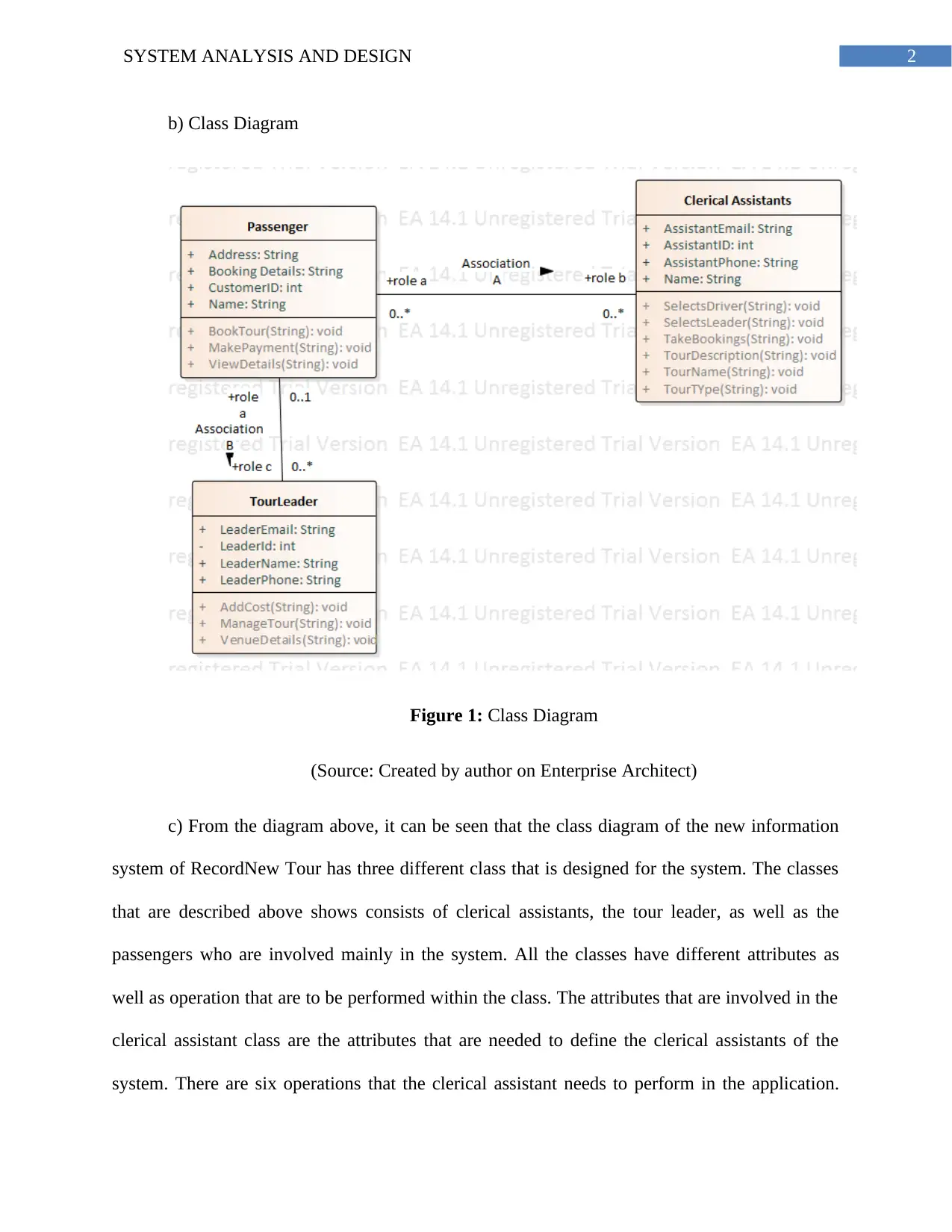
b) Class Diagram
Figure 1: Class Diagram
(Source: Created by author on Enterprise Architect)
c) From the diagram above, it can be seen that the class diagram of the new information
system of RecordNew Tour has three different class that is designed for the system. The classes
that are described above shows consists of clerical assistants, the tour leader, as well as the
passengers who are involved mainly in the system. All the classes have different attributes as
well as operation that are to be performed within the class. The attributes that are involved in the
clerical assistant class are the attributes that are needed to define the clerical assistants of the
system. There are six operations that the clerical assistant needs to perform in the application.
⊘ This is a preview!⊘
Do you want full access?
Subscribe today to unlock all pages.
Trusted by 1+ million students worldwide
3SYSTEM ANALYSIS AND DESIGN
The class of passenger has four attributes as well as three operations that are designed in the
class. There are total of four attributes in the class of Tour leader and this class will have three
operations that is to be performed in the class. There is an association between all the classes in
the diagram shown above. There is an association between the passenger class and the clerical
assistant class and there is also an association with the passenger class and the Tour leader class.
All the classes have public variable as well as private variable. The members cannot access the
variable that are private. All can access the variable that are public.
Communication Diagram
a) The main purpose of communication diagram is to show the main interaction between
all the users in a particular system. Communication diagram is commonly known as interaction
diagram that shows the interaction in between the objects. Communication diagram is mainly
done by extending the object diagram that shows all the objects with some messages for
traveling from one place to another place. The main motive of using the communication diagram
is drawing a message model, which passes between object or between the roles that delivers
functionalities used in the use cases as well as operations that are involved. Communication
diagram is commonly known as model mechanism.
Paraphrase This Document
Need a fresh take? Get an instant paraphrase of this document with our AI Paraphraser
4SYSTEM ANALYSIS AND DESIGN
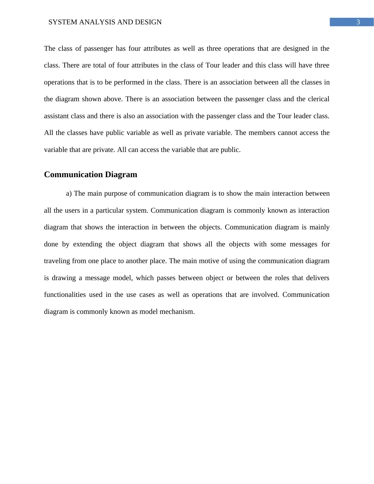
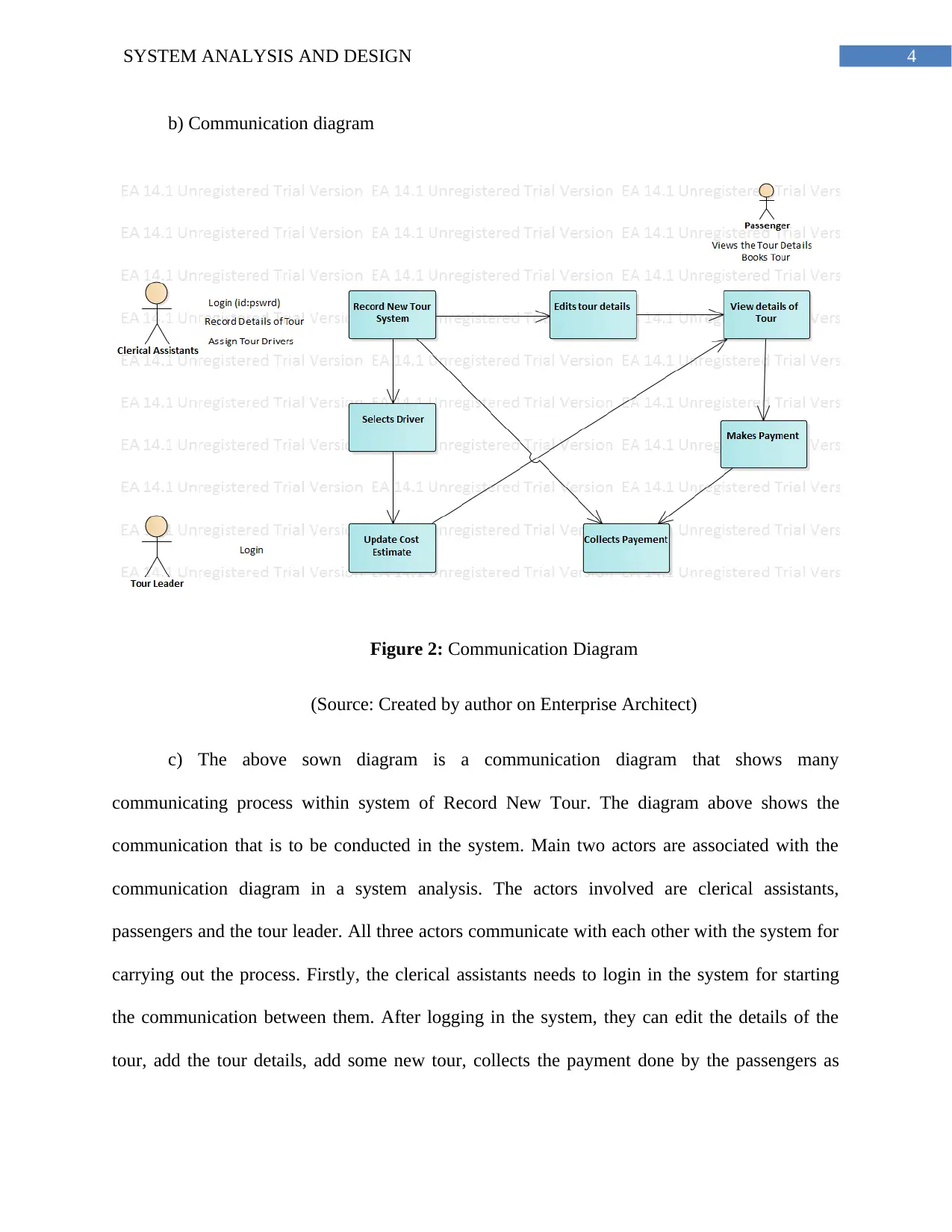
b) Communication diagram
Figure 2: Communication Diagram
(Source: Created by author on Enterprise Architect)
c) The above sown diagram is a communication diagram that shows many
communicating process within system of Record New Tour. The diagram above shows the
communication that is to be conducted in the system. Main two actors are associated with the
communication diagram in a system analysis. The actors involved are clerical assistants,
passengers and the tour leader. All three actors communicate with each other with the system for
carrying out the process. Firstly, the clerical assistants needs to login in the system for starting
the communication between them. After logging in the system, they can edit the details of the
tour, add the tour details, add some new tour, collects the payment done by the passengers as
5SYSTEM ANALYSIS AND DESIGN
well as can select the driver. The passengers can only view the tour details as well as can select
the tour they wants to travel. The passengers can also make their payment accordingly.
Part 2: Sequence Diagram
a) The need of sequence diagram is to show all the interactions in between the objects,
which comes in sequential, order of interaction they are carried out. Sequence diagram is mainly
useful because it shows about how the communication takes place in a particular business or in
particular system. Sequence diagram shows all the objects involved in a business in sequential
way. From a sequential diagram, the requirement of a business can be known and also the
requirement of communication needed for implementing the system in future is involved in a
sequence diagram. The developer or the analyst can improve the system use case in the
requirement phase and defines the working of an object in that system.
⊘ This is a preview!⊘
Do you want full access?
Subscribe today to unlock all pages.
Trusted by 1+ million students worldwide
6SYSTEM ANALYSIS AND DESIGN
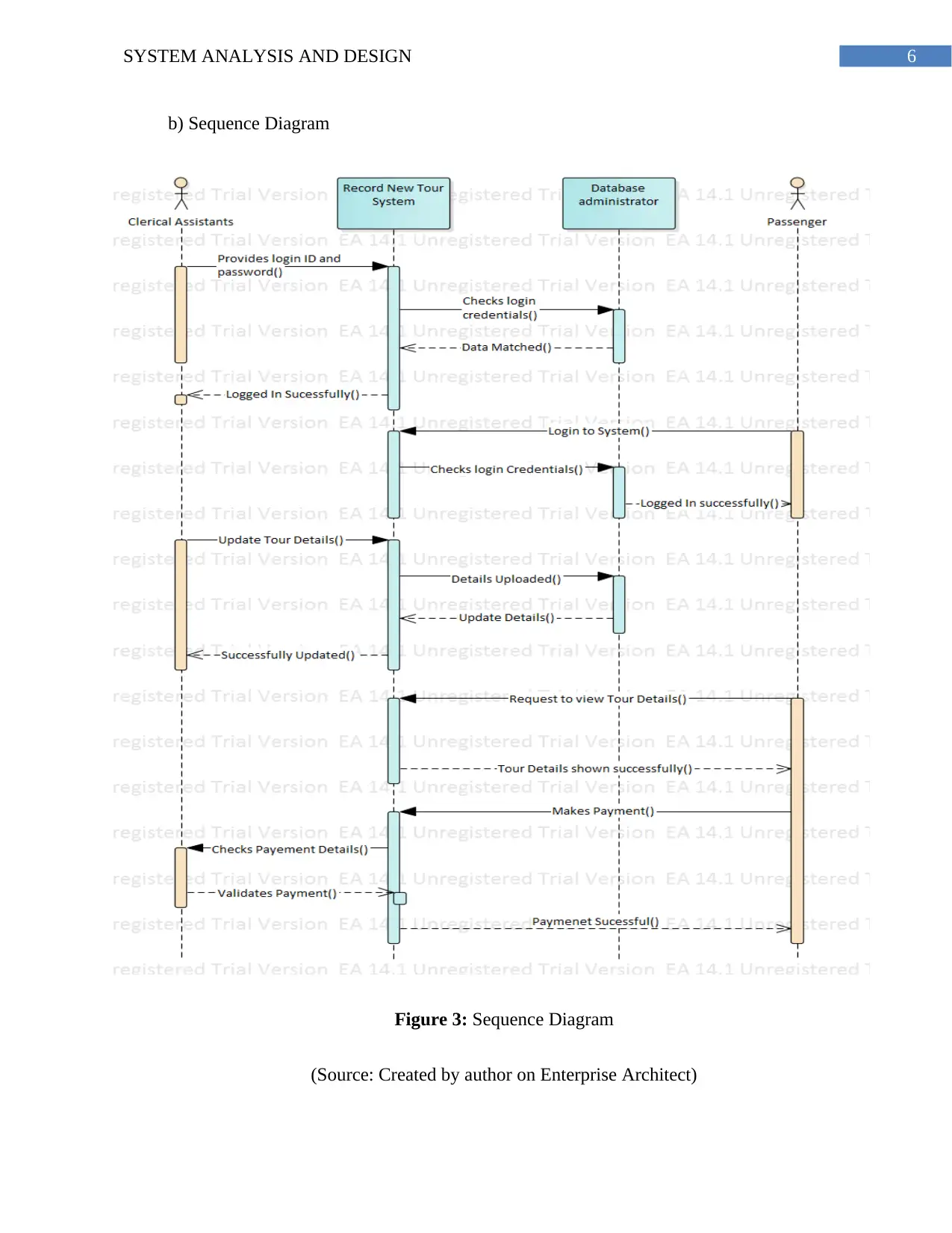
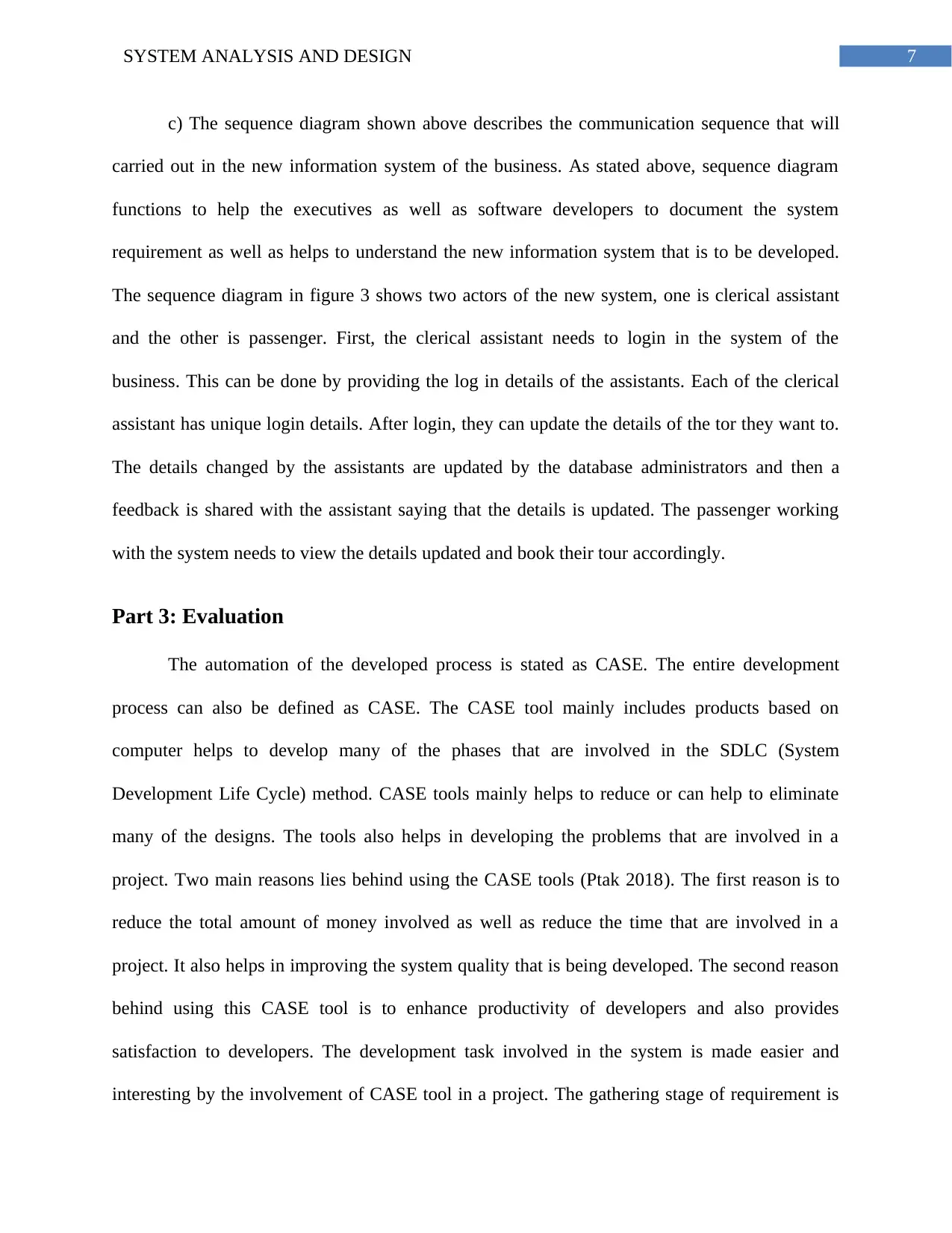
b) Sequence Diagram
Figure 3: Sequence Diagram
(Source: Created by author on Enterprise Architect)
b) Sequence Diagram
Figure 3: Sequence Diagram
(Source: Created by author on Enterprise Architect)
Paraphrase This Document
Need a fresh take? Get an instant paraphrase of this document with our AI Paraphraser
7SYSTEM ANALYSIS AND DESIGN
c) The sequence diagram shown above describes the communication sequence that will
carried out in the new information system of the business. As stated above, sequence diagram
functions to help the executives as well as software developers to document the system
requirement as well as helps to understand the new information system that is to be developed.
The sequence diagram in figure 3 shows two actors of the new system, one is clerical assistant
and the other is passenger. First, the clerical assistant needs to login in the system of the
business. This can be done by providing the log in details of the assistants. Each of the clerical
assistant has unique login details. After login, they can update the details of the tor they want to.
The details changed by the assistants are updated by the database administrators and then a
feedback is shared with the assistant saying that the details is updated. The passenger working
with the system needs to view the details updated and book their tour accordingly.
Part 3: Evaluation
The automation of the developed process is stated as CASE. The entire development
process can also be defined as CASE. The CASE tool mainly includes products based on
computer helps to develop many of the phases that are involved in the SDLC (System
Development Life Cycle) method. CASE tools mainly helps to reduce or can help to eliminate
many of the designs. The tools also helps in developing the problems that are involved in a
project. Two main reasons lies behind using the CASE tools (Ptak 2018). The first reason is to
reduce the total amount of money involved as well as reduce the time that are involved in a
project. It also helps in improving the system quality that is being developed. The second reason
behind using this CASE tool is to enhance productivity of developers and also provides
satisfaction to developers. The development task involved in the system is made easier and
interesting by the involvement of CASE tool in a project. The gathering stage of requirement is
8SYSTEM ANALYSIS AND DESIGN
formalized using the CASE tool and enables the system to develop a secured system and
maintain them properly. CASE tool helps to improve the quality of the system that is being
developed.
The developers gains many benefit from the CASE tool that are used for making the
system design. The developers can get the architecture of the system rather than focusing on the
coding of the system. The requirements involved with the system are given by the analysts using
a CASE tool and automatic the codes are generated for that. CASE tool also supports the reverse
engineering. In reverse engineering, the legacy of the system is mainly changed for designing
some of the specifications that are used to reconstruct the code that meets all the needs of the
business. The most important advantage that CASE tool provides is enabling the implementation
of the design philosophy for all the projects, system and the people (Mayan et al. 2016). Some
particular standard of development are followed by the CASE tools and those standards are
followed by the analyst who uses those CASE tools. All the procedures are utilized by the
development teams of different teams using CASE tool and also follows the methods that are
used to develop the aspect of the project. Sharing of information is also possible for the
development teams using the CASE tool. The model design are synchronized and the
implementation are also synchronized using CASE tool.
Feature that is supported by the CASE tool is system development of engineering. There
are many other features as well that are supported by the CASE tool. They are Diagram Support
that are automated, checking correctness of the syntactic and also can support the data dictionary
of the system developed. The CASE tool also checks consistency and the completeness of
system and also navigates the linked diagrams.
⊘ This is a preview!⊘
Do you want full access?
Subscribe today to unlock all pages.
Trusted by 1+ million students worldwide
9SYSTEM ANALYSIS AND DESIGN
Many analyst and developers does not use methodologies that includes paper and pen.
The CASE tool fear control loss in the design phase. The problems of usability are mainly
associated with CASE tool that discourages initial use as well as the continued use. There are
many tools that has substantial learning curve that includes much expensive time from a project.
With the involvement of CASE tool, the developing cost for the system increases gradually.
UML commonly known as Unified Modelling Language involves a technique, which
automates software production and also improves quality of the system and helps in reducing the
cost of the system. UML also saves time for designing. The technique that is involved in the
UML language includes the component technology, the patterns, visual programming, and the
frameworks that are involved in the project (Hare and Kaplan 2017). The UML language helps
the business to seek technique that manages the complexity of system that increases scope and
the scale of software. The users get ready to use model with the help of modelling along with
visual modelling that helps in developing and also exchanging all the models. Extensibility is
mainly provided along with specialization mechanisms that extends the main concepts and is
also independent for some of the particular programming languages and the development process
as well. UML mainly provides many formal basis, which understands the modelling language
and also encourages the object growth of the object-oriented tool. Unified Modelling Language
supports high-level development that includes components, frameworks, as well as collaboration
patterns.
Paraphrase This Document
Need a fresh take? Get an instant paraphrase of this document with our AI Paraphraser
10SYSTEM ANALYSIS AND DESIGN
Bibliography
Del Turco, R.R., Di Pietro, C. and Martignano, C., 2018. Designing a multi-layered User
Interface for EVT 2: a development report. AIUCD 2018, p.105.
Frank, U., Atkinson, C., Grossmann, G. and Clark, T., 2016. Designing Models and Systems to
Support IT Management: A Case for Multilevel Modeling. In MULTI@ MoDELS (pp. 3-24).
Hare, E. and Kaplan, A., 2017. Designing Modular Software: A Case Study in Introductory
Statistics. Journal of Computational and Graphical Statistics, 26(3), pp.493-500.
Kaur, T. and Sehra, S.K., 2015. Designing and development of database testing
tool. International Journal of Computer Applications, 120(19).
Kounev, S., Huber, N., Brosig, F. and Zhu, X., 2016. A model-based approach to designing self-
aware IT systems and infrastructures. Computer, 49(7), pp.53-61.
Mayan, J.A., Menezes, R.J. and George, M.B., 2016. Designing a Customized Testing Tool for
Windows Phones Utilizing Background Agents. In Proceedings of the International Conference
on Soft Computing Systems (pp. 33-46). Springer, New Delhi.
Pedreira, O., García, F., Brisaboa, N. and Piattini, M., 2015. Gamification in software
engineering–A systematic mapping. Information and software technology, 57, pp.157-168.
Ptak, P., 2018, May. APPLICATION OF THE SOFTWARE PACKAGE LTSPICE FOR
DESIGNING AND ANALYSING THE OPERATION OF ELECTRONIC SYSTEMS.
In Proceedings of the International Scientific Conference. Volume V (Vol. 402, p. 408).
Sahaf, Z., Garousi, V., Pfahl, D., Irving, R. and Amannejad, Y., 2014, May. When to automate
software testing? decision support based on system dynamics: an industrial case study.

11SYSTEM ANALYSIS AND DESIGN
In Proceedings of the 2014 International Conference on Software and System Process (pp. 149-
158). ACM.
In Proceedings of the 2014 International Conference on Software and System Process (pp. 149-
158). ACM.
⊘ This is a preview!⊘
Do you want full access?
Subscribe today to unlock all pages.
Trusted by 1+ million students worldwide
1 out of 13
Related Documents


Your All-in-One AI-Powered Toolkit for Academic Success.
+13062052269
info@desklib.com
Available 24*7 on WhatsApp / Email
![[object Object]](/_next/static/media/star-bottom.7253800d.svg)
Unlock your academic potential
Copyright © 2020–2026 A2Z Services. All Rights Reserved. Developed and managed by ZUCOL.