University Electrical Engineering Lab: Transformer Equivalent Circuit
VerifiedAdded on 2022/09/07
|19
|4460
|18
Practical Assignment
AI Summary
This assignment details a laboratory experiment focused on the analysis of a single-phase transformer's equivalent circuit. The experiment involves conducting open-circuit, short-circuit, and full-load tests on a 230V/230V, 50Hz, 100VA transformer. The open-circuit test is used to determine the turns ratio, magnetizing current characteristics, and the magnetizing components RM and XM. The short-circuit test is performed to find the primary-side winding resistance RSP and leakage inductance XSP. The full-load test examines the relationship between primary and secondary currents, and the assignment concludes with an on-load test to predict voltage regulation and efficiency. Calculations are performed to derive equivalent circuit parameters, and comparisons are made between predicted and measured values. The report includes detailed procedures, data tables, graphs, calculations, and analysis of the transformer's performance under various conditions.

Figure 1 Transformer equivalent circuit
The secondary winding resistance and leakage inductance components RSS and XSS
can be referred to the primary side using the transformer turns-ratio, where they are
denoted by RSS’ and XSS’ respectively as shown in Figure 2.
Figure 2 Transformer equivalent circuit secondary components
referred to primary
Using the assumption that the magnitudes of the impedances RSP, XSP, RSS’, XSS’ are
very much less than RM, XM, the elements RM and XM can be moved so that they
connect across the transformer input terminals. Consequently, RSS’ and XSS’ can be
lumped together with the primary-side impedances RSP and XSP to give the equivalent
components RS=RSP+RSS’ and XS=XSP+XSS’, as shown by the equivalent circuit in
Figure 3,
1
Paraphrase This Document
Need a fresh take? Get an instant paraphrase of this document with our AI Paraphraser
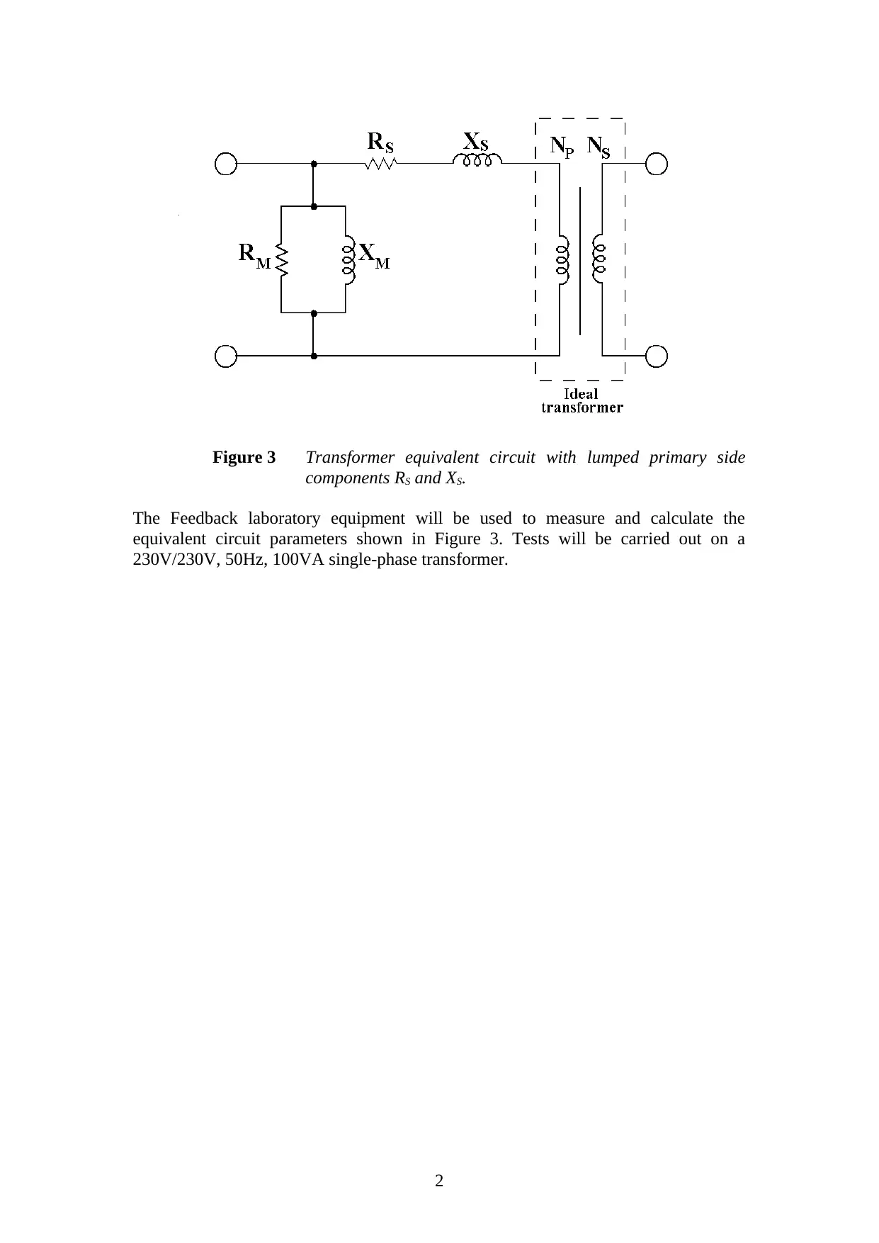
Figure 3 Transformer equivalent circuit with lumped primary side
components RS and XS.
The Feedback laboratory equipment will be used to measure and calculate the
equivalent circuit parameters shown in Figure 3. Tests will be carried out on a
230V/230V, 50Hz, 100VA single-phase transformer.
2
components RS and XS.
The Feedback laboratory equipment will be used to measure and calculate the
equivalent circuit parameters shown in Figure 3. Tests will be carried out on a
230V/230V, 50Hz, 100VA single-phase transformer.
2
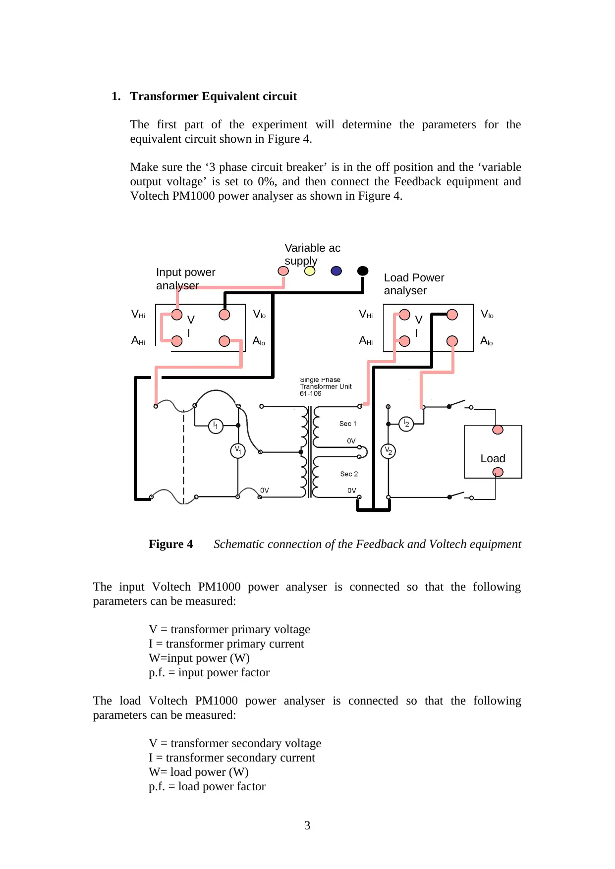
1. Transformer Equivalent circuit
The first part of the experiment will determine the parameters for the
equivalent circuit shown in Figure 4.
Make sure the ‘3 phase circuit breaker’ is in the off position and the ‘variable
output voltage’ is set to 0%, and then connect the Feedback equipment and
Voltech PM1000 power analyser as shown in Figure 4.
Figure 4 Schematic connection of the Feedback and Voltech equipment
The input Voltech PM1000 power analyser is connected so that the following
parameters can be measured:
V = transformer primary voltage
I = transformer primary current
W=input power (W)
p.f. = input power factor
The load Voltech PM1000 power analyser is connected so that the following
parameters can be measured:
V = transformer secondary voltage
I = transformer secondary current
W= load power (W)
p.f. = load power factor
3
V
I
VloVHi
AloAHi
V
I
VloVHi
AloAHi
Load
Variable ac
supply
Input power
analyser Load Power
analyser
⊘ This is a preview!⊘
Do you want full access?
Subscribe today to unlock all pages.
Trusted by 1+ million students worldwide
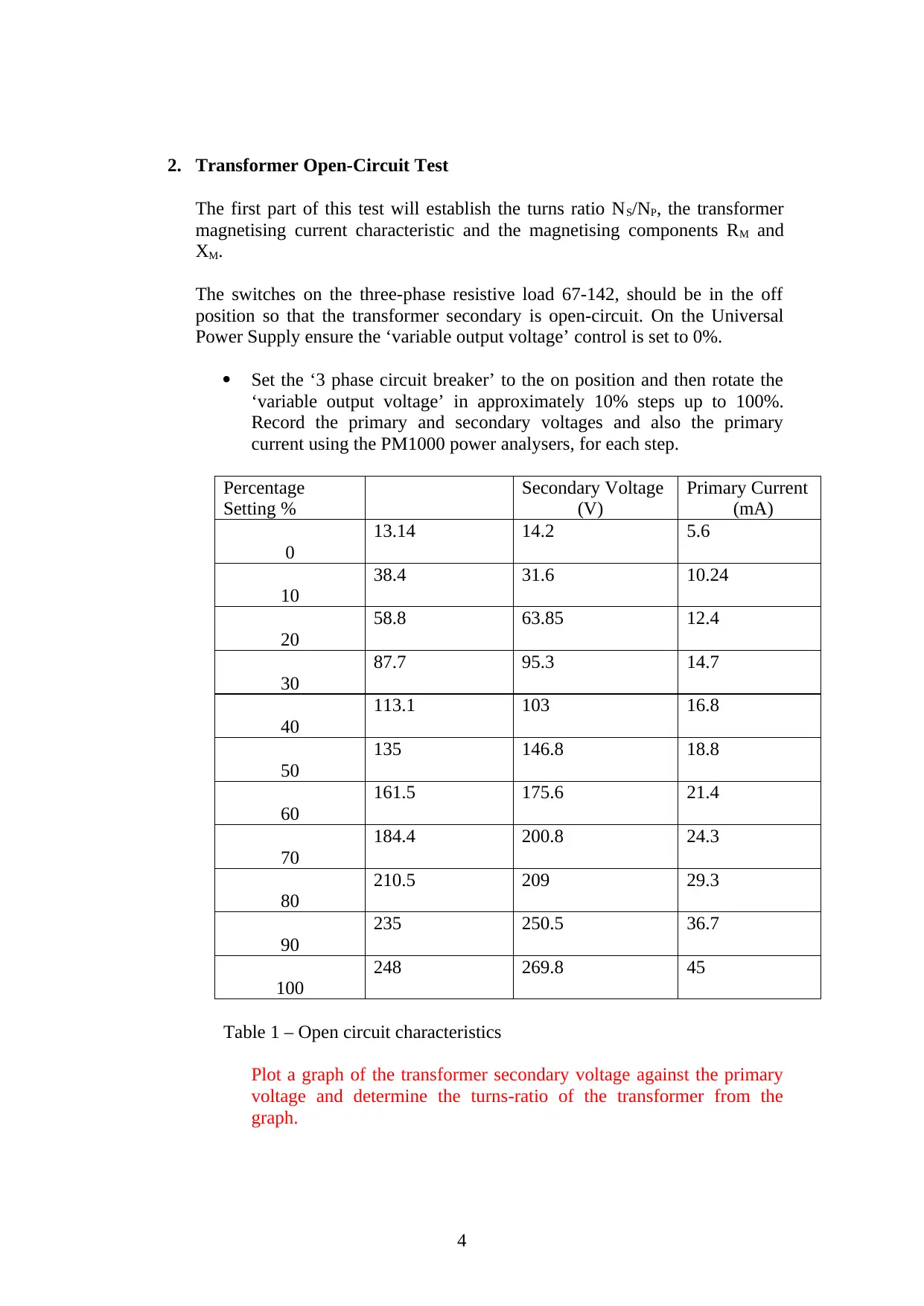
2. Transformer Open-Circuit Test
The first part of this test will establish the turns ratio NS/NP, the transformer
magnetising current characteristic and the magnetising components RM and
XM.
The switches on the three-phase resistive load 67-142, should be in the off
position so that the transformer secondary is open-circuit. On the Universal
Power Supply ensure the ‘variable output voltage’ control is set to 0%.
Set the ‘3 phase circuit breaker’ to the on position and then rotate the
‘variable output voltage’ in approximately 10% steps up to 100%.
Record the primary and secondary voltages and also the primary
current using the PM1000 power analysers, for each step.
Percentage
Setting %
Secondary Voltage
(V)
Primary Current
(mA)
0
13.14 14.2 5.6
10
38.4 31.6 10.24
20
58.8 63.85 12.4
30
87.7 95.3 14.7
40
113.1 103 16.8
50
135 146.8 18.8
60
161.5 175.6 21.4
70
184.4 200.8 24.3
80
210.5 209 29.3
90
235 250.5 36.7
100
248 269.8 45
Table 1 – Open circuit characteristics
Plot a graph of the transformer secondary voltage against the primary
voltage and determine the turns-ratio of the transformer from the
graph.
4
Paraphrase This Document
Need a fresh take? Get an instant paraphrase of this document with our AI Paraphraser

The relationship between primary, secondary and turns ratio is given
by the equation below
Vs / Vp = Ns /Np [1]………………1
Where Vs is the voltage at the secondary side of a transformer
Vp is the voltage at the primary side of a transformer
Ns is the number of turns at the secondary side
Np is the number of turns at the primary side
Multiplying both sides of equation 1 by Vp we get
Vs = (Ns /Np) * Vp……………2
Equation of a straight line is normally in the form of
y = mx + c
where m is the slope of the line and C is the intercept
Equation 2 represents the equation of the plotted line, therefore the
turns ratio is equivalent to the slope of the line.
Ns / Np = slope = (200-50) / (190 – 50) = 150 / 140
Turn ratio is thus 15 : 14
Compare and comment on the measured transformer secondary voltage
considering the rating of the transformer.
The voltage rating of the transformer is 230V, however the maximum
no load terminal voltage is slightly higher than the transformer ratings.
When the transformer is fully loaded, the rated current is drawn
through the secondary circuit, thus sufficient voltage drop. With the
secondary circuit open circuited, the no-load current is too small in
magnitude, resulting in little voltage drop, thus a higher terminal
voltage.
Plot the primary voltage against the primary (magnetising) current and
comment on the shape of the curve.
5

The curve is divided into two regions; the linear region and saturation
region. In the linear region, magnetising current increases in direct
proportion to the primary voltage, the slope of the curve is steep. In
saturation region, the slope of the curve is less steep compared to linear
region. Transformation ratio of the transformer is distorted since the
secondary current is distorted by saturation of transformer core.
With the primary voltage set to 230V, record the primary voltage and
secondary voltage, and using the power analyser measure the primary
current and primary active power.
Primary Voltage
(V)
Primary Current
(mA)
Primary Power
(W)
230.5 35 4.89
Table 2 – Open circuit test results at nominal primary voltage.
From these measurements calculate the transformer equivalent core-
loss resistance RM and the magnetising reactance XM. Mark these
values on an equivalent circuit of the transformer. Hint - use the
equation , where P is the active power, V and I are the
primary voltage and current and M is the phase angle between the
voltage and current. Separate the primary current into resistive and
inductive components and hence calculate RM and XM.
P0 = V1 I0 Cos ∅M
Where V1 and I0 are primary voltage and current respectively
The power factor at no load is thus
Cos ∅M = P / VI
Substituting the values of power, current and voltage we get
= 4.89 / (230.5 * 0.035)
= 0.60614
6
⊘ This is a preview!⊘
Do you want full access?
Subscribe today to unlock all pages.
Trusted by 1+ million students worldwide
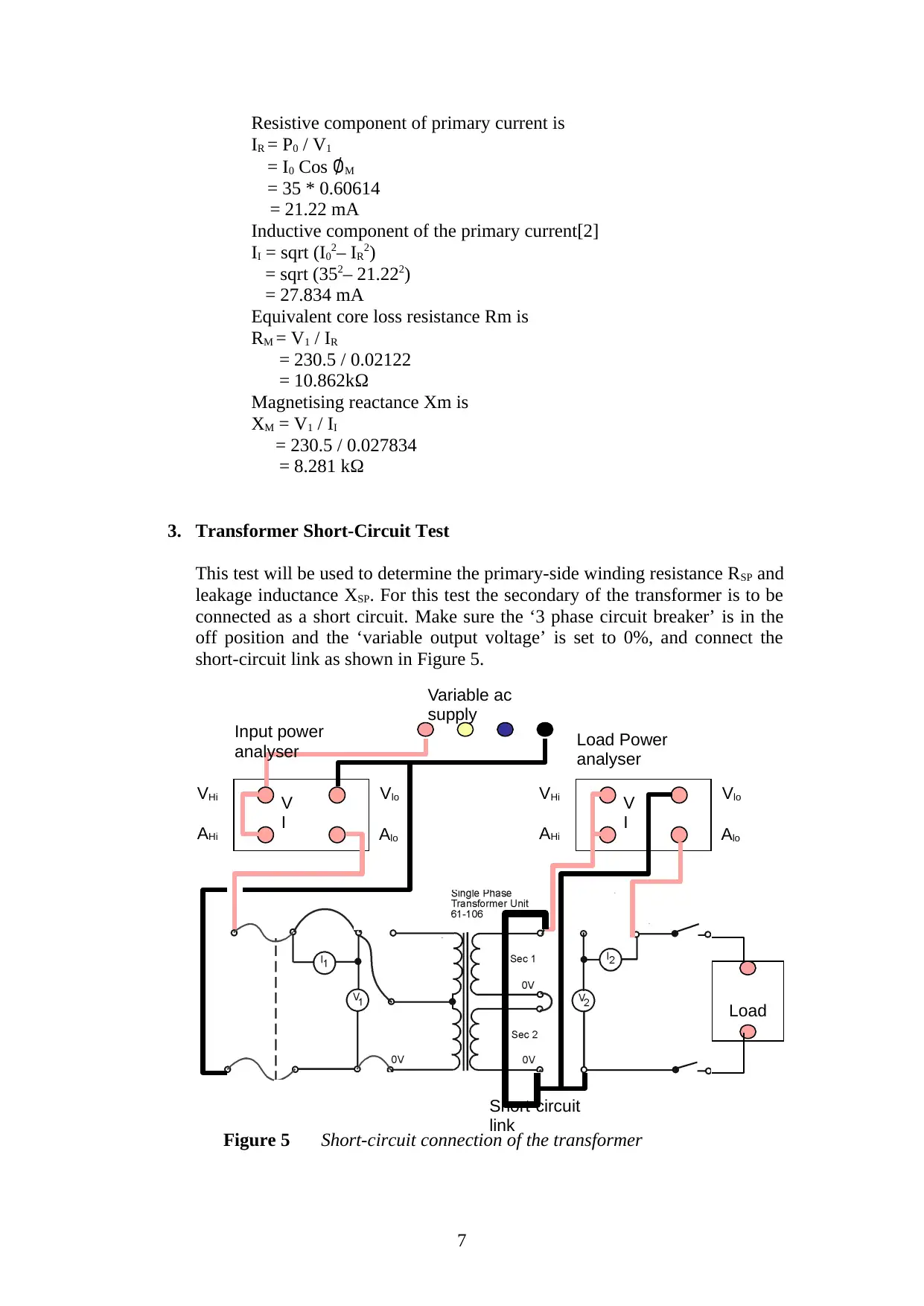
Resistive component of primary current is
IR = P0 / V1
= I0 Cos ∅M
= 35 * 0.60614
= 21.22 mA
Inductive component of the primary current[2]
II = sqrt (I02– IR2)
= sqrt (352– 21.222)
= 27.834 mA
Equivalent core loss resistance Rm is
RM = V1 / IR
= 230.5 / 0.02122
= 10.862kΩ
Magnetising reactance Xm is
XM = V1 / II
= 230.5 / 0.027834
= 8.281 kΩ
3. Transformer Short-Circuit Test
This test will be used to determine the primary-side winding resistance RSP and
leakage inductance XSP. For this test the secondary of the transformer is to be
connected as a short circuit. Make sure the ‘3 phase circuit breaker’ is in the
off position and the ‘variable output voltage’ is set to 0%, and connect the
short-circuit link as shown in Figure 5.
Figure 5 Short-circuit connection of the transformer
7
V
I
VloVHi
AloAHi
V
I
VloVHi
AloAHi
Load
Variable ac
supply
Input power
analyser Load Power
analyser
Short-circuit
link
Paraphrase This Document
Need a fresh take? Get an instant paraphrase of this document with our AI Paraphraser
Ask the laboratory supervisor to check your circuit before
continuing.
If you have not already done so, calculate the value of the transformer
rated current.
Set the ‘3 phase circuit breaker’ to the on position and slowly rotate the
‘variable output voltage’ until the secondary current is equal to its rated
current. The ‘variable output voltage’ control should be set at just
under 10%, if you are unable to generate the required secondary
current with the supply control in this position, seek assistance from
the laboratory supervisor.
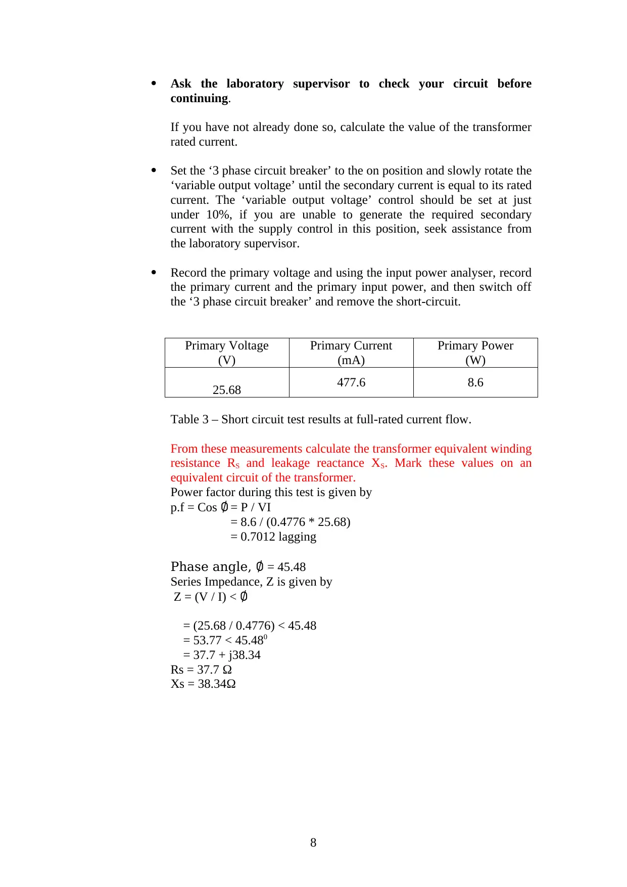
Record the primary voltage and using the input power analyser, record
the primary current and the primary input power, and then switch off
the ‘3 phase circuit breaker’ and remove the short-circuit.
Primary Voltage
(V)
Primary Current
(mA)
Primary Power
(W)
25.68 477.6 8.6
Table 3 – Short circuit test results at full-rated current flow.
From these measurements calculate the transformer equivalent winding
resistance RS and leakage reactance XS. Mark these values on an
equivalent circuit of the transformer.
Power factor during this test is given by
p.f = Cos ∅ = P / VI
= 8.6 / (0.4776 * 25.68)
= 0.7012 lagging
Phase angle, ∅ = 45.48
Series Impedance, Z is given by
Z = (V / I) < ∅
= (25.68 / 0.4776) < 45.48
= 53.77 < 45.480
= 37.7 + j38.34
Rs = 37.7 Ω
Xs = 38.34Ω
8
continuing.
If you have not already done so, calculate the value of the transformer
rated current.
Set the ‘3 phase circuit breaker’ to the on position and slowly rotate the
‘variable output voltage’ until the secondary current is equal to its rated
current. The ‘variable output voltage’ control should be set at just
under 10%, if you are unable to generate the required secondary
current with the supply control in this position, seek assistance from
the laboratory supervisor.
Record the primary voltage and using the input power analyser, record
the primary current and the primary input power, and then switch off
the ‘3 phase circuit breaker’ and remove the short-circuit.
Primary Voltage
(V)
Primary Current
(mA)
Primary Power
(W)
25.68 477.6 8.6
Table 3 – Short circuit test results at full-rated current flow.
From these measurements calculate the transformer equivalent winding
resistance RS and leakage reactance XS. Mark these values on an
equivalent circuit of the transformer.
Power factor during this test is given by
p.f = Cos ∅ = P / VI
= 8.6 / (0.4776 * 25.68)
= 0.7012 lagging
Phase angle, ∅ = 45.48
Series Impedance, Z is given by
Z = (V / I) < ∅
= (25.68 / 0.4776) < 45.48
= 53.77 < 45.480
= 37.7 + j38.34
Rs = 37.7 Ω
Xs = 38.34Ω
8
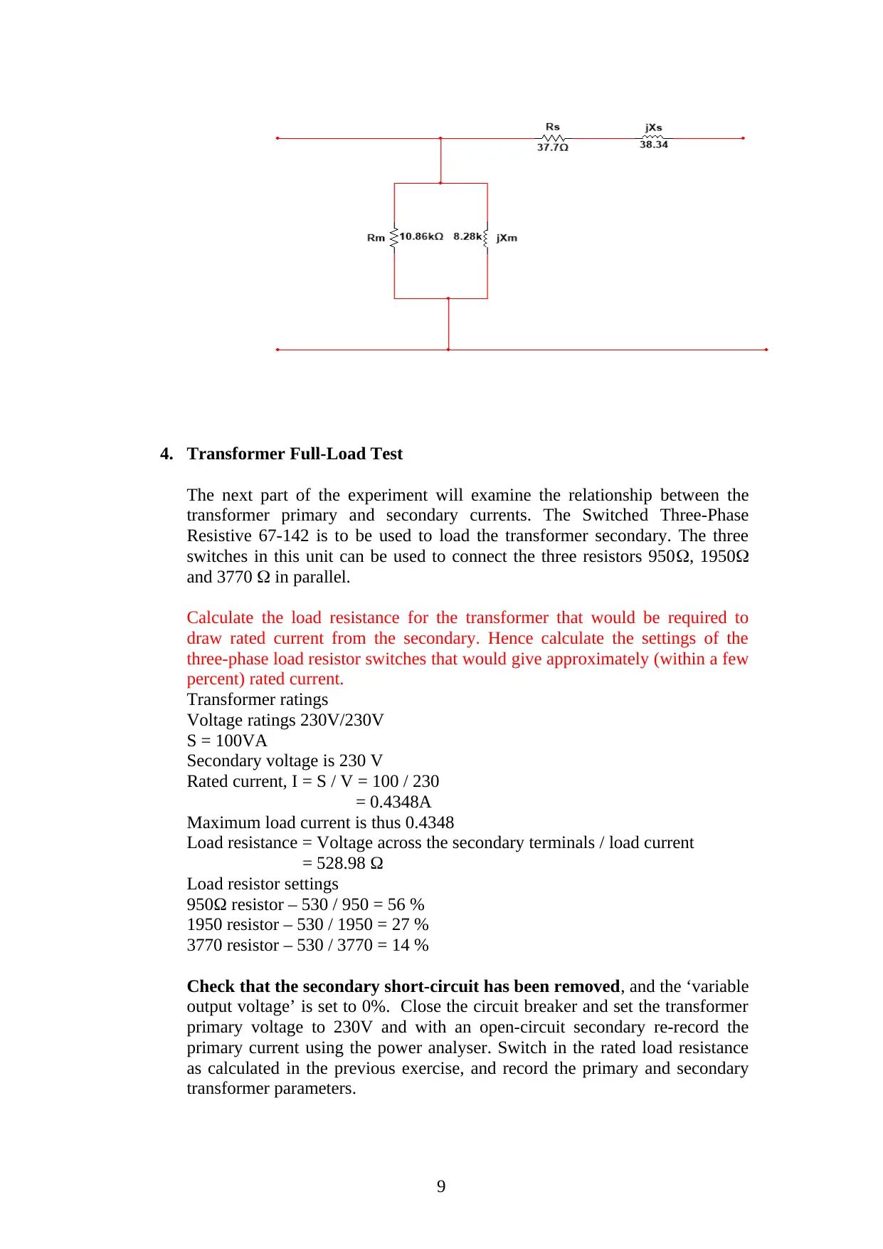
4. Transformer Full-Load Test
The next part of the experiment will examine the relationship between the
transformer primary and secondary currents. The Switched Three-Phase
Resistive 67-142 is to be used to load the transformer secondary. The three
switches in this unit can be used to connect the three resistors 950, 1950
and 3770 in parallel.
Calculate the load resistance for the transformer that would be required to
draw rated current from the secondary. Hence calculate the settings of the
three-phase load resistor switches that would give approximately (within a few
percent) rated current.
Transformer ratings
Voltage ratings 230V/230V
S = 100VA
Secondary voltage is 230 V
Rated current, I = S / V = 100 / 230
= 0.4348A
Maximum load current is thus 0.4348
Load resistance = Voltage across the secondary terminals / load current
= 528.98 Ω
Load resistor settings
950Ω resistor – 530 / 950 = 56 %
1950 resistor – 530 / 1950 = 27 %
3770 resistor – 530 / 3770 = 14 %
Check that the secondary short-circuit has been removed, and the ‘variable
output voltage’ is set to 0%. Close the circuit breaker and set the transformer
primary voltage to 230V and with an open-circuit secondary re-record the
primary current using the power analyser. Switch in the rated load resistance
as calculated in the previous exercise, and record the primary and secondary
transformer parameters.
9
⊘ This is a preview!⊘
Do you want full access?
Subscribe today to unlock all pages.
Trusted by 1+ million students worldwide
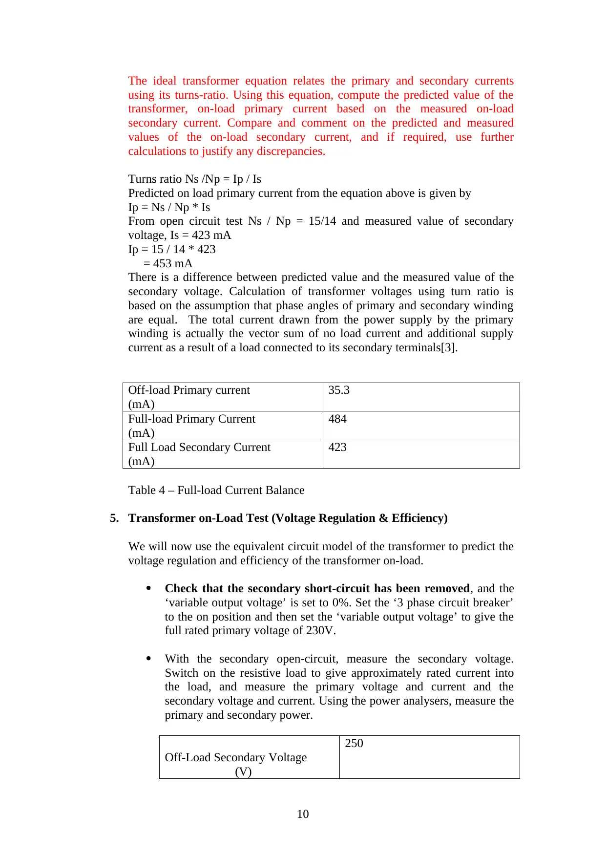
The ideal transformer equation relates the primary and secondary currents
using its turns-ratio. Using this equation, compute the predicted value of the
transformer, on-load primary current based on the measured on-load
secondary current. Compare and comment on the predicted and measured
values of the on-load secondary current, and if required, use further
calculations to justify any discrepancies.
Turns ratio Ns /Np = Ip / Is
Predicted on load primary current from the equation above is given by
Ip = Ns / Np * Is
From open circuit test Ns / Np = 15/14 and measured value of secondary
voltage, Is = 423 mA
Ip = 15 / 14 * 423
= 453 mA
There is a difference between predicted value and the measured value of the
secondary voltage. Calculation of transformer voltages using turn ratio is
based on the assumption that phase angles of primary and secondary winding
are equal. The total current drawn from the power supply by the primary
winding is actually the vector sum of no load current and additional supply
current as a result of a load connected to its secondary terminals[3].
Off-load Primary current
(mA)
35.3
Full-load Primary Current
(mA)
484
Full Load Secondary Current
(mA)
423
Table 4 – Full-load Current Balance
5. Transformer on-Load Test (Voltage Regulation & Efficiency)
We will now use the equivalent circuit model of the transformer to predict the
voltage regulation and efficiency of the transformer on-load.
Check that the secondary short-circuit has been removed, and the
‘variable output voltage’ is set to 0%. Set the ‘3 phase circuit breaker’
to the on position and then set the ‘variable output voltage’ to give the
full rated primary voltage of 230V.
With the secondary open-circuit, measure the secondary voltage.
Switch on the resistive load to give approximately rated current into
the load, and measure the primary voltage and current and the
secondary voltage and current. Using the power analysers, measure the
primary and secondary power.
Off-Load Secondary Voltage
(V)
250
10
Paraphrase This Document
Need a fresh take? Get an instant paraphrase of this document with our AI Paraphraser
Primary voltage (on-
load) (V)
Primary Current
(mA)
W1
(W)
229.3
481.3 109.5
Secondary voltage
(on-load) (V)
Secondary Current
(mA)
W2
(W)
229.3 421.0 96.2
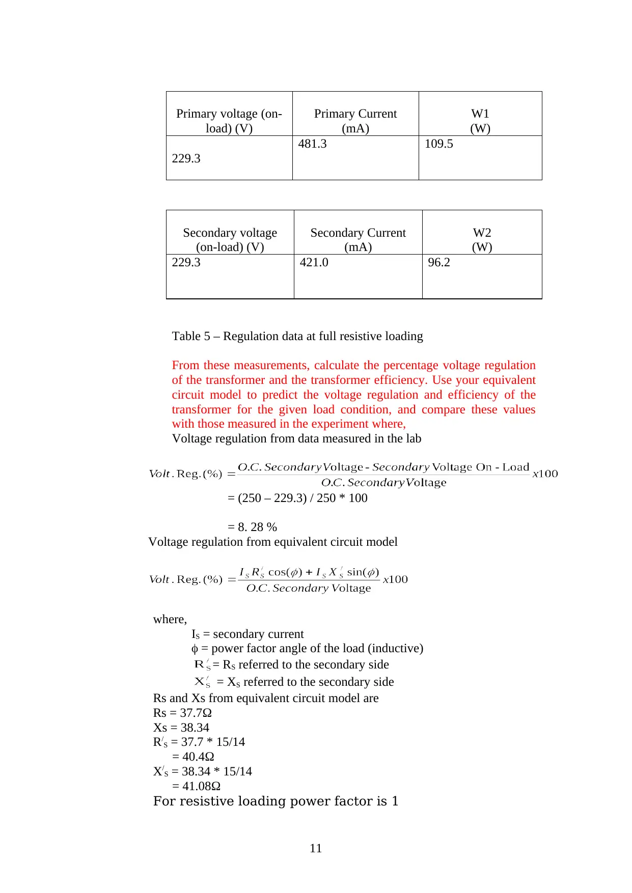
Table 5 – Regulation data at full resistive loading
From these measurements, calculate the percentage voltage regulation
of the transformer and the transformer efficiency. Use your equivalent
circuit model to predict the voltage regulation and efficiency of the
transformer for the given load condition, and compare these values
with those measured in the experiment where,
Voltage regulation from data measured in the lab
= (250 – 229.3) / 250 * 100
= 8. 28 %
Voltage regulation from equivalent circuit model
where,
IS = secondary current
= power factor angle of the load (inductive)
= RS referred to the secondary side
= XS referred to the secondary side
Rs and Xs from equivalent circuit model are
Rs = 37.7Ω
Xs = 38.34
R/S = 37.7 * 15/14
= 40.4Ω
X/S = 38.34 * 15/14
= 41.08Ω
For resistive loading power factor is 1
11
load) (V)
Primary Current
(mA)
W1
(W)
229.3
481.3 109.5
Secondary voltage
(on-load) (V)
Secondary Current
(mA)
W2
(W)
229.3 421.0 96.2
Table 5 – Regulation data at full resistive loading
From these measurements, calculate the percentage voltage regulation
of the transformer and the transformer efficiency. Use your equivalent
circuit model to predict the voltage regulation and efficiency of the
transformer for the given load condition, and compare these values
with those measured in the experiment where,
Voltage regulation from data measured in the lab
= (250 – 229.3) / 250 * 100
= 8. 28 %
Voltage regulation from equivalent circuit model
where,
IS = secondary current
= power factor angle of the load (inductive)
= RS referred to the secondary side
= XS referred to the secondary side
Rs and Xs from equivalent circuit model are
Rs = 37.7Ω
Xs = 38.34
R/S = 37.7 * 15/14
= 40.4Ω
X/S = 38.34 * 15/14
= 41.08Ω
For resistive loading power factor is 1
11
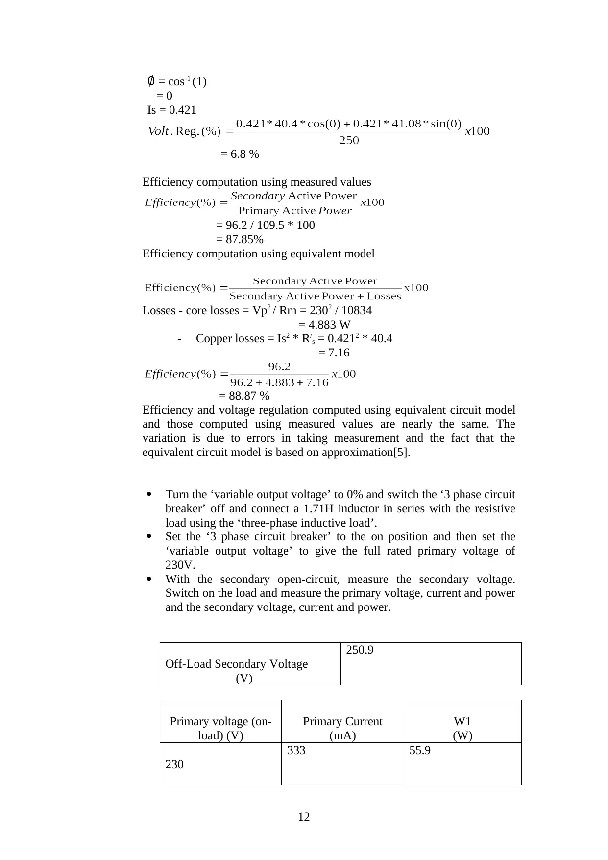
∅ = cos-1 (1)
= 0
Is = 0.421
= 6.8 %
Efficiency computation using measured values
= 96.2 / 109.5 * 100
= 87.85%
Efficiency computation using equivalent model
Losses - core losses = Vp2 / Rm = 2302 / 10834
= 4.883 W
- Copper losses = Is2 * R/s = 0.4212 * 40.4
= 7.16
= 88.87 %
Efficiency and voltage regulation computed using equivalent circuit model
and those computed using measured values are nearly the same. The
variation is due to errors in taking measurement and the fact that the
equivalent circuit model is based on approximation[5].
Turn the ‘variable output voltage’ to 0% and switch the ‘3 phase circuit
breaker’ off and connect a 1.71H inductor in series with the resistive
load using the ‘three-phase inductive load’.
Set the ‘3 phase circuit breaker’ to the on position and then set the
‘variable output voltage’ to give the full rated primary voltage of
230V.
With the secondary open-circuit, measure the secondary voltage.
Switch on the load and measure the primary voltage, current and power
and the secondary voltage, current and power.
Off-Load Secondary Voltage
(V)
250.9
Primary voltage (on-
load) (V)
Primary Current
(mA)
W1
(W)
230
333 55.9
12
⊘ This is a preview!⊘
Do you want full access?
Subscribe today to unlock all pages.
Trusted by 1+ million students worldwide
1 out of 19


Your All-in-One AI-Powered Toolkit for Academic Success.
+13062052269
info@desklib.com
Available 24*7 on WhatsApp / Email
![[object Object]](/_next/static/media/star-bottom.7253800d.svg)
Unlock your academic potential
Copyright © 2020–2026 A2Z Services. All Rights Reserved. Developed and managed by ZUCOL.