Improve Transient Stability of IEEE 9 Bus System Using STATCOM

Verified

Added on  2022/08/21

|5
|585
|19
Project
AI Summary
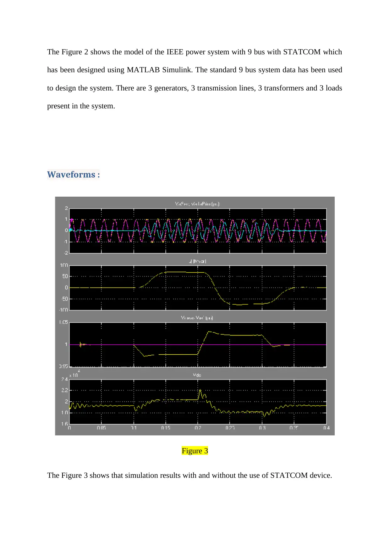
This project focuses on enhancing the transient stability of an IEEE 9 bus power system using a STATCOM, a shunt FACTS device. The system is modeled and simulated in MATLAB Simulink. The STATCOM, comprising a Voltage Source Inverter (VSI) and a gate pulse generator, is connected to the transmission line via a coupling transformer. The simulation results, comparing the system with and without STATCOM, demonstrate that the STATCOM reduces fault magnitude, compensates for reactive power, and improves the voltage profile, thereby enhancing the overall transient response. The project details the design of the STATCOM, including the gate pulse generation circuit and the VSI, and analyzes the waveforms to illustrate the device's impact on system stability. The IEEE 9 bus system consists of three generators, three transmission lines, three transformers and three loads. The results show how STATCOM improves the transmission capacity, reduces the losses and improves the voltage profile of the system under fault conditions. The use of STATCOM device improves the transient response of the system.
Document Page
Electrical Engg.
Transient Stability Analysis
Student Name –
Student ID -
Introduction :
The stability of the power system with 9 bus( which is in the state of fault ) can be improved
by the help of the STATCOM which is shunt FACTS system. The model of the IEEE system
with 9 bus can be designed by employing Simulink from MATLAB.
The STATCOM consists of 2 parts : VSI ( Voltage Source Inverter ) and a circuit to generate
the gate pulse. A coupling transformer can be used for connecting it to a transmission line.
The waveforms have been obtained for the system using STATCOM as well as without using
STATCOM. It can be observed that the magnitude of the fault decreases and the reactive
power gets compensated when STATCOM is used. The voltage profile also improves by
using STATCOM.
STATCOM is a type of shunt controller employed for power injection and voltage
modulation. A transmission line is connected using a coupling transformer. The controller has
been used to absorb the reactive power or to supply it. STATCOM's basic concept is to
tabler-icon-diamond-filled.svg

Paraphrase This Document

Need a fresh take? Get an instant paraphrase of this document with our AI Paraphraser
Document Page
produce controllable A. C. source of voltage at back of transformer leakage reaction having a
VSC connected with the DC storage capacitor. The difference of the voltage over reaction
generates transfers of active as well as reactive power between the STATCOM and the
control grid.
The STATCOM used here is a gate pulse generator circuit, that can be used to produce the
gate pulses for the voltage source inverter IGBT / Diode firing. VSI is employed for the
generation of the output voltage. The input of the gate pulse generator has been provided as a
three-current that is further converted by park transformation to d-frame of reference, then its
value is compared by the PI controller to the reference voltage and again changed to three
phase ia, ib and ic current which feed into three separate PI controllers. Here it is compared to
the triangular wave, and if the condition is met then pulses are produced which are the input
to the VSI. Voltage Source Inverter has IGBT / Diode filters that are used to produce output
voltage.
1. Simulation without statcom
The Figure 1 shows the model of the IEEE power system with 9 bus without using
STATCOM which has been designed using MATLAB Simulink. The standard 9 bus system
data has been used to design the system.
Document Page
Figure 1
2. Simulation with statcom
Figure 2
Document Page
The Figure 2 shows the model of the IEEE power system with 9 bus with STATCOM which
has been designed using MATLAB Simulink. The standard 9 bus system data has been used
to design the system. There are 3 generators, 3 transmission lines, 3 transformers and 3 loads
present in the system.
Waveforms :
Figure 3
The Figure 3 shows that simulation results with and without the use of STATCOM device.
tabler-icon-diamond-filled.svg

Paraphrase This Document

Need a fresh take? Get an instant paraphrase of this document with our AI Paraphraser
Document Page
The results of simulation show that by using the STATCOM device, the transmission
capacity of the device has been improved. Magnitude for fault decreased and the losses
associated with the system have also decreased. The reactive power has been compensated by
the STATCOM device. As the voltage profile has also improved, it can be concluded that the
transient response of the system has been improved.
chevron_up_icon
1 out of 5
circle_padding
hide_on_mobile
zoom_out_icon
[object Object]