Transport Network Design Report: Enterprise Network Solutions
VerifiedAdded on 2020/11/23
|19
|4785
|328
Report
AI Summary
This report provides a comprehensive overview of transport network design, focusing on the creation and utilization of computer networks concerning hardware, software, and protocols. It explores various network design models such as the three-tier and two-tier hierarchical models, along with the features of scalable networks. The report delves into LAN, bandwidth, and load redundancy within Layer 2 and Layer 3 of the OSI model. It covers the selection and configuration of LAN devices, the implementation of LAN design with Layer 2 and Layer 3 redundancy using switches and routers. Furthermore, the report examines WAN technologies for enterprise networks and configures WAN protocols. It also discusses the deployment of network monitoring tools and troubleshooting methods to establish network baselines, along with addressing WAN and LAN connectivity issues across various layers. The report incorporates practical configurations and implementations to provide a detailed understanding of enterprise network solutions.

Transport Network
Design
Design
Paraphrase This Document
Need a fresh take? Get an instant paraphrase of this document with our AI Paraphraser
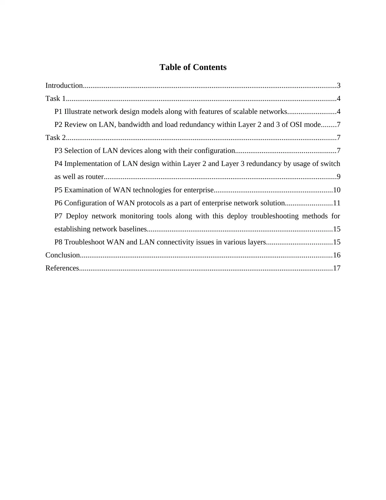
Table of Contents
Introduction......................................................................................................................................3
Task 1...............................................................................................................................................4
P1 Illustrate network design models along with features of scalable networks..........................4
P2 Review on LAN, bandwidth and load redundancy within Layer 2 and 3 of OSI mode........7
Task 2...............................................................................................................................................7
P3 Selection of LAN devices along with their configuration.....................................................7
P4 Implementation of LAN design within Layer 2 and Layer 3 redundancy by usage of switch
as well as router...........................................................................................................................9
P5 Examination of WAN technologies for enterprise...............................................................10
P6 Configuration of WAN protocols as a part of enterprise network solution.........................11
P7 Deploy network monitoring tools along with this deploy troubleshooting methods for
establishing network baselines..................................................................................................15
P8 Troubleshoot WAN and LAN connectivity issues in various layers...................................15
Conclusion.....................................................................................................................................16
References......................................................................................................................................17
Introduction
Networking refers to practice of exchanging and transporting data between nodes who are
share a medium within information system. Basically, it is a entire process for creation and usage
of computer networks with reference to software, hardware and protocols (Alshamsi and Diabat,
2015). The connections can be established between them either by making use of wireless and
wired technology. Generally, a network comprises of various devices which interacts with each
other. It enables endpoints and devices to connect with one other or large network by usage of
either private WAN or internet. This assignment contains models of network design,
redundancies associated with bandwidth, LAN and load issues within Layer 3 and Layer 2.
Furthermore, configuration of LAN is provided along with their implementation. Apart from
this, WAN technologies are identified and various protocols associated with this are configured.
Along with this, monitoring tools as well as troubleshooting methods are established and issues
with WAN & LAN are handled.
Task 1
P1 Illustrate network design models along with features of scalable networks.
System design which deals with mechanism of data transport is referred to network
design. This comprises of analysis stage in which requirements are analysed and with
implementation is carried out (Botton and et. al., 2013). The process of designing is done before
execution and accordingly next steps are done. can make use any one of the models which are
illustrated below:
Three-tier hierarchical network model
To acknowledge technical as well as customer's goals within corporate network design
there needs to be network topology which comprises of interconnected components. By making
use of hierarchical network design model a topology can be developed in different layers. It
includes three layers, they are access, distribution and core layer. These layers are illustrated
below with respect to :
Core layer: It is one of the expensive, fastest and expensive router which comprises of
highest model number. It is a spine of network which is being used for blending separated
networks. They are responsible for moving information among networks as soon as possible. In
context of , they can make use of this layer to have optimum transport among high performance
⊘ This is a preview!⊘
Do you want full access?
Subscribe today to unlock all pages.
Trusted by 1+ million students worldwide
routing and sites (Bovy and Stern, 2012). Design principles associated with core must render
suitable level of resilience which will provide ability for recovering smoothly and quickly after
the network has failed within core block.
Distribution layer: This acts as intermediate among access and core layers in which well
designed network routing functions are found. It provides boundary definition by implementation
of access lists as well as other filters. It defines the policies for network within high end layer 3
switches. Distribution layer makes sure that packets are routed within VLANs and subnets within
enterprise. With respect to this, traffic will be localised such as database servers or departmental
files of . In this security aspects with respect to filtering and access lists are taken into account
along with boundary control & policy based connectivity (De Rosa and et. Al, 2013).
Access layer: This layer comprises of switches that are connected to computers, servers
or printers which are commonly referred to as end devices. Switches in this layer will make sure
that packets are transferred. It renders user/workgroup access to network, in this aspect, common
hierarchical design and two primary architectures of enterprise campus networks are two-tier and
three-tier layer models.
(Source: Cisco three-layer hierarchical model, 2019)
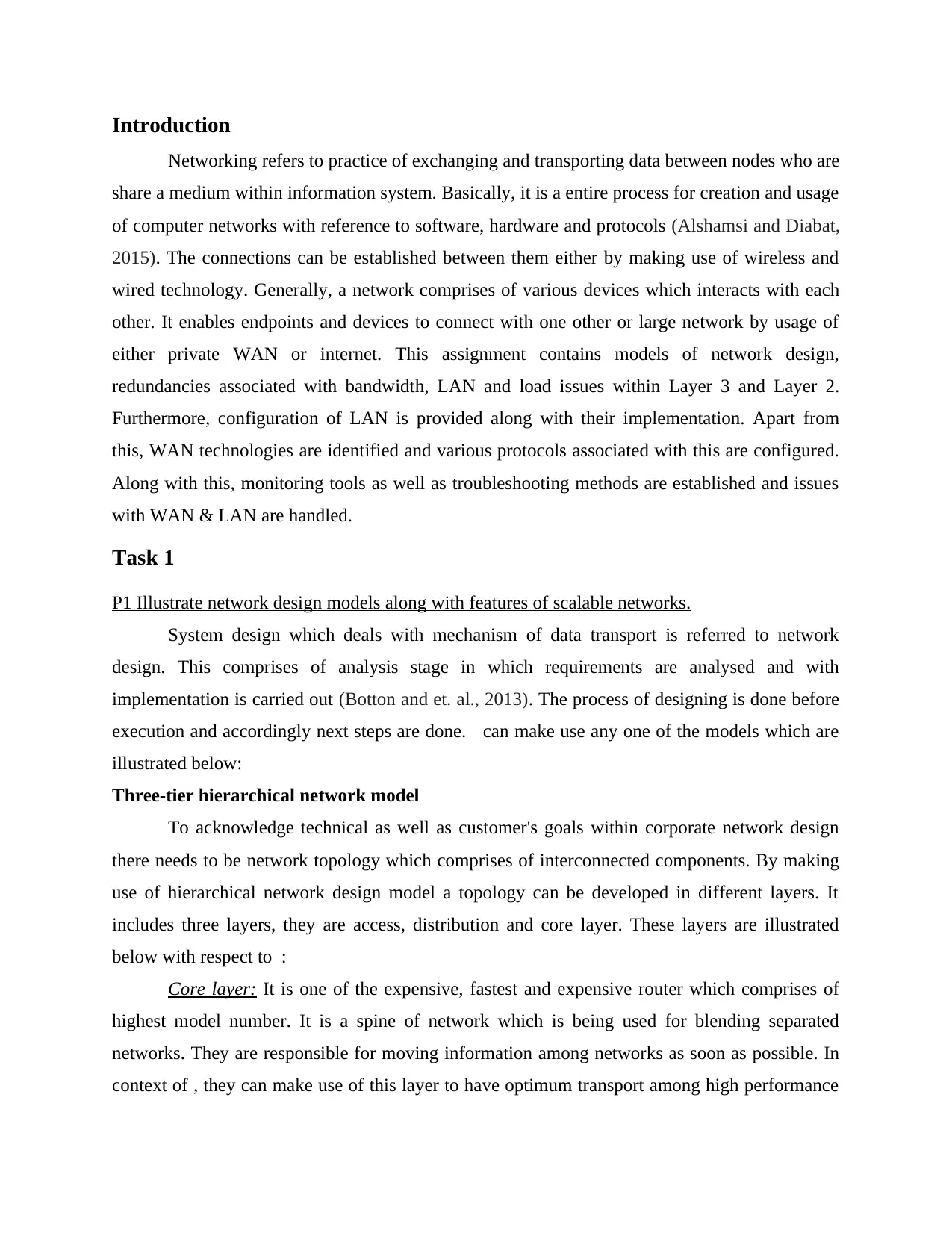
Two-tier hierarchical network model
Illustration 1: Three-tier architecture
suitable level of resilience which will provide ability for recovering smoothly and quickly after
the network has failed within core block.
Distribution layer: This acts as intermediate among access and core layers in which well
designed network routing functions are found. It provides boundary definition by implementation
of access lists as well as other filters. It defines the policies for network within high end layer 3
switches. Distribution layer makes sure that packets are routed within VLANs and subnets within
enterprise. With respect to this, traffic will be localised such as database servers or departmental
files of . In this security aspects with respect to filtering and access lists are taken into account
along with boundary control & policy based connectivity (De Rosa and et. Al, 2013).
Access layer: This layer comprises of switches that are connected to computers, servers
or printers which are commonly referred to as end devices. Switches in this layer will make sure
that packets are transferred. It renders user/workgroup access to network, in this aspect, common
hierarchical design and two primary architectures of enterprise campus networks are two-tier and
three-tier layer models.
(Source: Cisco three-layer hierarchical model, 2019)
Two-tier hierarchical network model
Illustration 1: Three-tier architecture
Paraphrase This Document
Need a fresh take? Get an instant paraphrase of this document with our AI Paraphraser
The design in which distribution and core layers are collapsed into a single layer are very
practical. A collapsed core occurs when core and distribution layer functions are executed by a
individual device. The major benefit of this is reduced network cost along with maintaining
benefits associated with three-tier hierarchical model. It is often used within medium to small
size campus networks (Demuth and et. Al, 2014).
Features of Scalable networks
Scalability refers to property which deals with handling of rapidly growing needs by
adding more resources within the system. Depending on demands of market as well as customers
there is need to make changes within existing system. Therefore, it is necessary for that they
must have flexible systems so that they can make necessary changes with respect to
requirements. They are illustrated below:
Quality of services must be provided for different protocols as well as applications
without making any worst desktop scenario. Internetwork must be capable for generating
responses related with issues of latency without compromising quality.
Responsive network must render QoS for different protocols and applications without
making worst impact on systems.
Adaptable network includes various applications, hardware technologies and protocols,
this is also one of the important feature of scalability (Farahani and et. Al, 2013).
Illustration 2: Two-tier architecture
Network integrity can be maintained by allowing connections by making use of switched,
dedicated and dialup services.
Cisco IOS provides high set of features which assists to support high scalability of
network. Large internetwork needs optimise needs of resources specially bandwidth and also
enhance data throughout without buying or adding WAN services within existing system. This
will aid to eliminate unnecessary service location requests, broadcasts and routing updates.
P2 Review on LAN, bandwidth and load redundancy within Layer 2 and 3 of OSI mode.
Network redundancy is defined as a process through which additional or alternate instances
of networks, communication mediums and equipments are installed in infrastructure
(Govindan, Fattah and Keyvanshokooh, 2017). It will make sure availability of network
devices if network path is broken down or failed and may be unavailable. Generally, they
act as a backup in this case.
Layer 2: This allows building up or establishing physical network connections among server and
client which assist in networking as well as provides a network path for similar data
processing. In this case if any single network is failed then entire network will fail and
transmission of messages will not take place (Keyvanshokooh, Ryan and Kabir, 2016).
Layer 3: In this HSRP (Hot Standby Router Protocol) can be used which provides
multilayer switches as well as routers to look alike a identical gateway IP address. It is used for
rendering redundancy within layer 3 functions in a network implemented by . Furthermore,
various standards protocols are their which can be utilised. For this one switch can be disabled
when normal operations are being carried out and it takes over when other fails. IEEE 802.1D
standard specifies STP (Spanning tree protocol) for implementation of avoidance of loops as
well as redundancy. This protocol provides faster recovery from failures. Network layer works
for transmitting data from one host to the other within various networks (Layer 3 Designs, 2019).
Task 2
P3 Selection of LAN devices along with their configuration.
As per the needs of , they are shown below:
Department Devices
Finance 9 Desktop
⊘ This is a preview!⊘
Do you want full access?
Subscribe today to unlock all pages.
Trusted by 1+ million students worldwide
IT 5 Computers
Sales 65 PC's
Design 40 Computers
Servers (DNS, web, email and file) 4 Servers
Printer is attached with each of department. The IP address of each branch is
192.168.168.0/24 and address of private branch is 192.168.1.0/24. Along with this, IP address of
WAN is 30.40.50.168/28. For addressing these demands routers and switch can be used. Packets
are router by router on the basis of IP addresses as well as for connecting LAN and WAN. Along
with this, routing table is upgraded with respect to routing data packets (Kim, 2014). A multi
port bridge within data link layer have design and buffer that will increase performance and
efficiency along with this before packets are transmitted error checking is done.
Configuration commands for network connectivity: Requests are sent in the form data
packets within network in . There are different configuration commands that are shown below:
I. Packet internet groper (Ping): This ensures that systems can communicate with specific
devices that are in network (Larsen and Urry, 2016). This command will provide information
such as number of packets is being sent, received and time taken for them. They can be
understood by following instances:
ping 192.168.168.1
This will provide details of whether this specific IP address is in network or not
ping facebook.com
It will return the time which is taken by packets to find speed of connection.
ii. nslookup: For querying DNS to address mapping by network administration, this command
line tool can be utilised. Such as:
nslookup google.com
By this administrator can make query to DNS to have domain name from IP address
along with Domain name server records.
iii. Arp: This command will show and alter cache which comprises of IP address mapping
towards MAC address. An instance can be taken:
arp
Paraphrase This Document
Need a fresh take? Get an instant paraphrase of this document with our AI Paraphraser
MAC address will be returned with respect to IP address of particular system.
iv. traceroute: This command shows the route of packets which can be used for identification of
path through which packets are travelling. This is shown below:
traceroute www.linkedin.com
It will return list of hosts and number of hops which are taken by packets while travelling
to destination.
v. netstat: The network statistics (netstat) shows status of ports, connection information, details
saved within routing table, its updation, etc. An instance can be taken to understand this:
netstat
This will show details of files which are present within file system of linux.
P4 Implementation of LAN design within Layer 2 and Layer 3 redundancy by usage of switch as
well as router.
Layer 2: Node to node packets delivery can be established within data link layer. By this,
it can be made sure that data transfer rates which were obtained are error free. With respect to
this, network level redundancy within Ethernet switch, multiple connections can be established
among networking devices (Mahaboob Sheriff, Gunasekaran and Nachiappan, 2012). Switches
can take over if any off the network fails, means switching takes place when anyone of the
switch stops responding to request which are made by systems. Spanning tree protocol within
IEEE 802.1D specifies the certain standards for avoiding redundancy as well as loops.
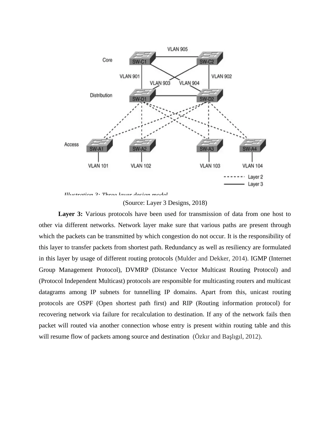
(Source: Layer 3 Designs, 2018)
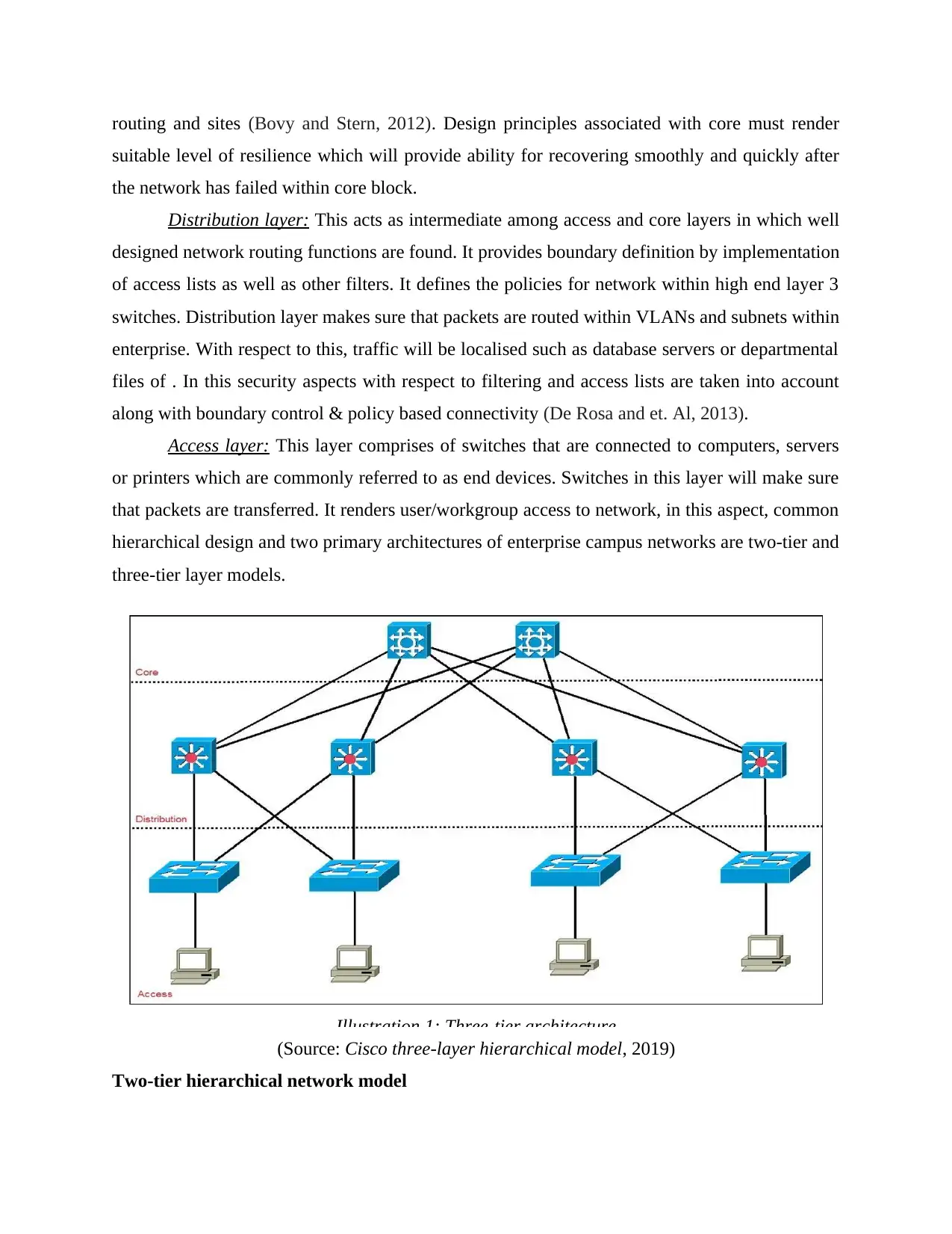
Layer 3: Various protocols have been used for transmission of data from one host to
other via different networks. Network layer make sure that various paths are present through
which the packets can be transmitted by which congestion do not occur. It is the responsibility of
this layer to transfer packets from shortest path. Redundancy as well as resiliency are formulated
in this layer by usage of different routing protocols (Mulder and Dekker, 2014). IGMP (Internet
Group Management Protocol), DVMRP (Distance Vector Multicast Routing Protocol) and
(Protocol Independent Multicast) protocols are responsible for multicasting routers and multicast
datagrams among IP subnets for tunnelling IP domains. Apart from this, unicast routing
protocols are OSPF (Open shortest path first) and RIP (Routing information protocol) for
recovering network via failure for recalculation to destination. If any of the network fails then
packet will routed via another connection whose entry is present within routing table and this
will resume flow of packets among source and destination (Özkır and Başlıgıl, 2012).
Illustration 3: Three layer design model
⊘ This is a preview!⊘
Do you want full access?
Subscribe today to unlock all pages.
Trusted by 1+ million students worldwide
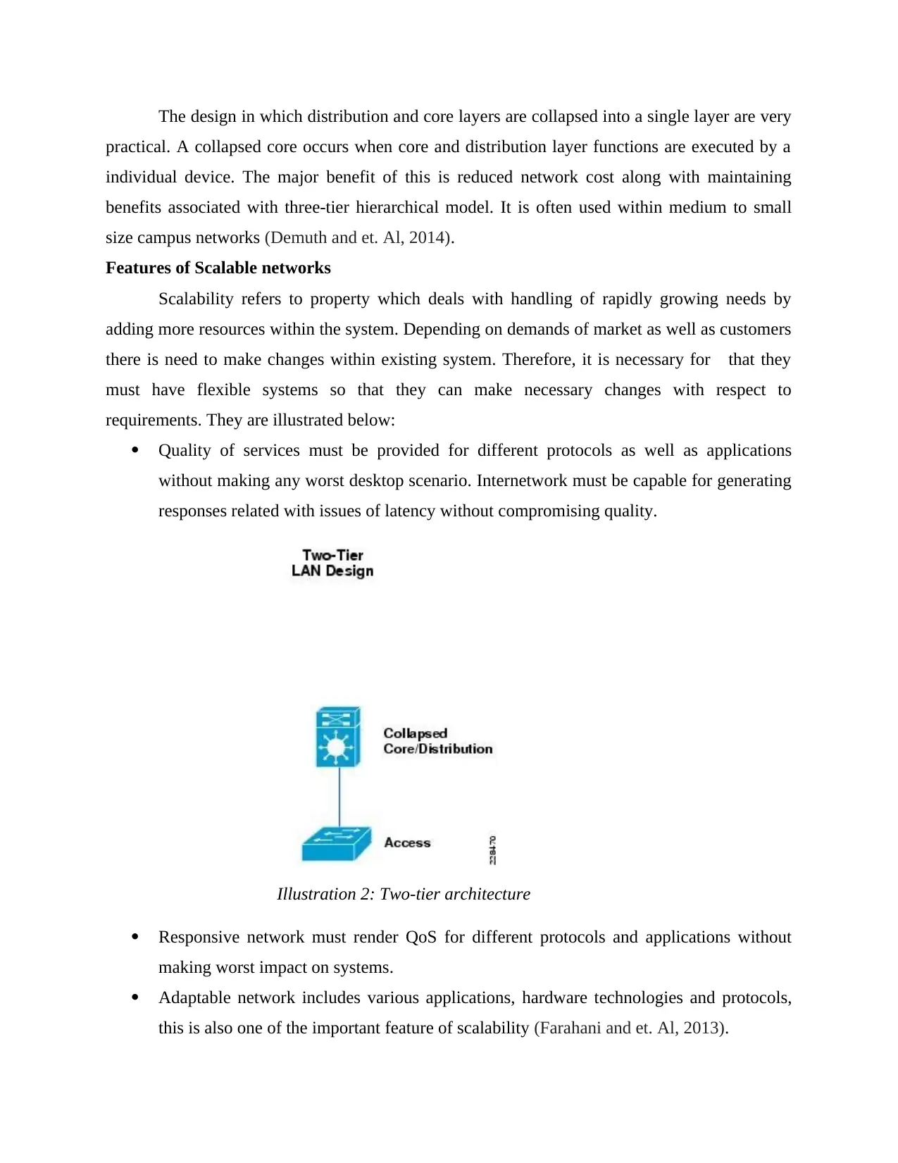
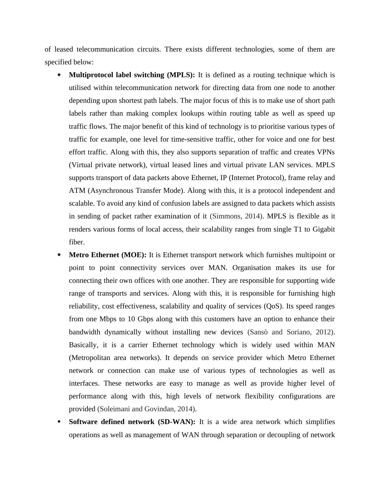
P5 Examination of WAN technologies for enterprise.
Wide area network refers to telecommunication networks which spreads over wide
geographical distance for the major purpose of networking. Basically, it is formulated by usage
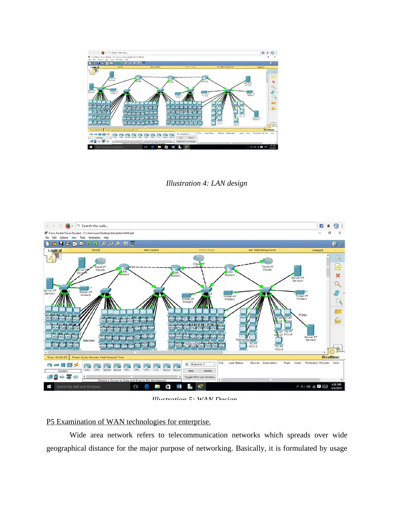
Illustration 4: LAN design
Illustration 5: WAN Design
Wide area network refers to telecommunication networks which spreads over wide
geographical distance for the major purpose of networking. Basically, it is formulated by usage
Illustration 4: LAN design
Illustration 5: WAN Design
Paraphrase This Document
Need a fresh take? Get an instant paraphrase of this document with our AI Paraphraser
of leased telecommunication circuits. There exists different technologies, some of them are
specified below:
Multiprotocol label switching (MPLS): It is defined as a routing technique which is
utilised within telecommunication network for directing data from one node to another
depending upon shortest path labels. The major focus of this is to make use of short path
labels rather than making complex lookups within routing table as well as speed up
traffic flows. The major benefit of this kind of technology is to prioritise various types of
traffic for example, one level for time-sensitive traffic, other for voice and one for best
effort traffic. Along with this, they also supports separation of traffic and creates VPNs
(Virtual private network), virtual leased lines and virtual private LAN services. MPLS
supports transport of data packets above Ethernet, IP (Internet Protocol), frame relay and
ATM (Asynchronous Transfer Mode). Along with this, it is a protocol independent and
scalable. To avoid any kind of confusion labels are assigned to data packets which assists
in sending of packet rather examination of it (Simmons, 2014). MPLS is flexible as it
renders various forms of local access, their scalability ranges from single T1 to Gigabit
fiber.
Metro Ethernet (MOE): It is Ethernet transport network which furnishes multipoint or
point to point connectivity services over MAN. Organisation makes its use for
connecting their own offices with one another. They are responsible for supporting wide
range of transports and services. Along with this, it is responsible for furnishing high
reliability, cost effectiveness, scalability and quality of services (QoS). Its speed ranges
from one Mbps to 10 Gbps along with this customers have an option to enhance their
bandwidth dynamically without installing new devices (Sansò and Soriano, 2012).
Basically, it is a carrier Ethernet technology which is widely used within MAN
(Metropolitan area networks). It depends on service provider which Metro Ethernet
network or connection can make use of various types of technologies as well as
interfaces. These networks are easy to manage as well as provide higher level of
performance along with this, high levels of network flexibility configurations are
provided (Soleimani and Govindan, 2014).
Software defined network (SD-WAN): It is a wide area network which simplifies
operations as well as management of WAN through separation or decoupling of network
hardware from their control mechanism. It improvises virtualisation by usage of data
centre operations and management. It interconnects enterprise networks such as data
centre and branch offices. Basically, it is an application associated with software defined
networking which is applied to broadband internet, MPLS, or LTE. It is responsible to
improvising agility as well as performance of business applications. They optimise
experience of users along with efficiency for public cloud applications and software as a
service (SaaS). Furthermore, SD-WAN simplifies cloud-based management and
operations associated with automation. The major benefit which is provided by this is,
enhanced security, these features are distributed at branch level (Szigeti and et. Al,
2013). Organisation can make use SD-WAN as it renders high security as well as it is
easier to build up hybrid-WAN through identification of right balance among reliability,
cost and performance within a various mix of traffic within applications. It will assist to
get control over complex networks by effectively altering changing requirements of
businesses. Furthermore, they can also monitor working conditions of every WAN link
and dynamic path can be used through which steer traffic down happens. By this
network engineers can respond to dynamic needs for new WAN services as well as
modifications within existing.
P6 Configuration of WAN protocols as a part of enterprise network solution.
Enterprise network refers to communication backbone which is responsible for
connecting every system at different locations. Basically, it is a large corporate network which
extends beyond heterogeneous sites worldwide and nationwide that comprises of WAN, MAN
and LAN according to needs of an enterprise (Talaei and et. Al, 2016). There are various
protocols which are utilised within WAN like PPP, ISDN, DSL, PPPoE and many others. In this
section configuration of PPPoE has been illustrated.
Point-to-Point Protocol (PPPoE): It is a network configuration which is utilised for
establishment of PPP (Point-to-Point) connection over an Ethernet protocol. This protocol is
widely used for transmission of data over a network which allows to establish identical server
connection (Yan and et. Al, 2013). Usually, it is utilised with DSL services in which individual
users are connected with DSL modem.
Configuration of PPPoE Client
The steps involved in this are illustrated below:
⊘ This is a preview!⊘
Do you want full access?
Subscribe today to unlock all pages.
Trusted by 1+ million students worldwide
1 out of 19
Related Documents

Your All-in-One AI-Powered Toolkit for Academic Success.
+13062052269
info@desklib.com
Available 24*7 on WhatsApp / Email
![[object Object]](/_next/static/media/star-bottom.7253800d.svg)
Unlock your academic potential
Copyright © 2020–2026 A2Z Services. All Rights Reserved. Developed and managed by ZUCOL.