Transport Network Design Report: Enterprise Network Design Analysis
VerifiedAdded on 2020/10/22
|24
|5810
|493
Report
AI Summary
This report provides a detailed analysis of transport network design, focusing on the needs of The Sage Group Plc. It begins by exploring various network design models, including the Cisco three-layer model and two-tier designs, along with the features of scalable networks. The report then delves into bandwidth, load, and redundancy issues within LANs, offering solutions at different OSI model layers. It examines router and switch redundancy protocols, such as VRRP and virtual switch redundancy, and their effectiveness. The selection of LAN devices based on requirements and features, alongside the application of configuration commands for network connectivity, is also covered. Furthermore, the report scrutinizes WAN technologies and configures them within an enterprise network solution. Finally, it discusses the deployment of network monitoring tools and troubleshooting methods for establishing network baselines, addressing both LAN and WAN connectivity issues across different networking layers.

Transport Network
Design
Design
Paraphrase This Document
Need a fresh take? Get an instant paraphrase of this document with our AI Paraphraser
Table of Contents
INTRODUCTION...........................................................................................................................1
P1 Analyse network design models as well as features of scalable networks with respect to
business needs........................................................................................................................1
P2 Discuss bandwidth, load and redundancy issues within LAN and solution with reference to
layer........................................................................................................................................4
P3 Selection of LAN devices on the basis of requirements and features by application of
configuration commands for network connectivity................................................................4
P4 Implementation of LAN design within Layer 2 and Layer 3 redundancy by making use of
router and switch redundancy protocols.................................................................................6
P5 Scrutiny of WAN technologies and selection of suitable one for a set of enterprise
requirements...........................................................................................................................7
P6 Configure WAN protocols within enterprise network solution........................................9
P7 Deploy network monitoring tools and troubleshooting methods for establishment of
network baselines.................................................................................................................11
P8 Troubleshoot various WAN and LAN connectivity issues within various networking
layers.....................................................................................................................................11
CONCLUSION..............................................................................................................................11
Online...............................................................................................................................................1
Source: Redundancy: Choosing the Right Option for Net Designs. 2019. [Online]. Available
through: <https://www.eetimes.com/document.asp?doc_id=1276954>.........................................1

⊘ This is a preview!⊘
Do you want full access?
Subscribe today to unlock all pages.
Trusted by 1+ million students worldwide
INTRODUCTION
Network refers to a system of unified devices which can interact by using similar
standards which are known as protocol. These devices are responsible for carrying out
communication by exchanging resources such as printers, files, applications and many others.
The network in which end-to-end communication occurs is known as transport network
(Alshamsi and Diabat, 2015). It furnish logical communication among application processes
which runs on hosts in a layered architecture. This report is based on The Sage Group Plc, which
is a limited company and a British multinational enterprise software organisation. It is
headquartered in Newcastle upon Tyne, England. It is one of the largest supplier to small
businesses. This report deals with network design models along with features of scalable
networks. Furthermore, bandwidth, LAN redundancy and load issues within layer 2 and layer 3
of OSI model are evaluated. Along with this features and requirements of LAN devices are
selected and implementation of LAN design has carried out. Apart from this, WAN technologies
are examined and they are configured as enterprise network solution. At last, network monitoring
tools are deployed and connectivity issues at different layers are handled.
P1 Analyse network design models as well as features of scalable networks with respect to
business needs.
Planning of building up a computer network infrastructure is referred to network design.
The designing process is carried out by network engineers, designers, IT administrators and other
staff. It is carried out before the process of execution is carried out (Botton and et. al., 2013). For
this, there are different models, some of them are illustrated below:
Cisco three layer or three-tier hierarchical network model: It divides critical flat
network multiple and manageable networks. Each level within hierarchy focus on particular set
of roles. This model renders The Sage Group Plc. with high degree of flexibility to attain
optimisation and make appropriate selection of feature, software and hardware. This comprises
of access layer, distribution layer and core layer. These layers are specified below:
Core layer: It renders optimum transport between high-performance and sites during
routing. This layer act as a backbone in high speed switch (Bovy and Stern, 2012). This creates
relevant impact on performance as each frame must be recreated as they passes via a each router.
1
Paraphrase This Document
Need a fresh take? Get an instant paraphrase of this document with our AI Paraphraser
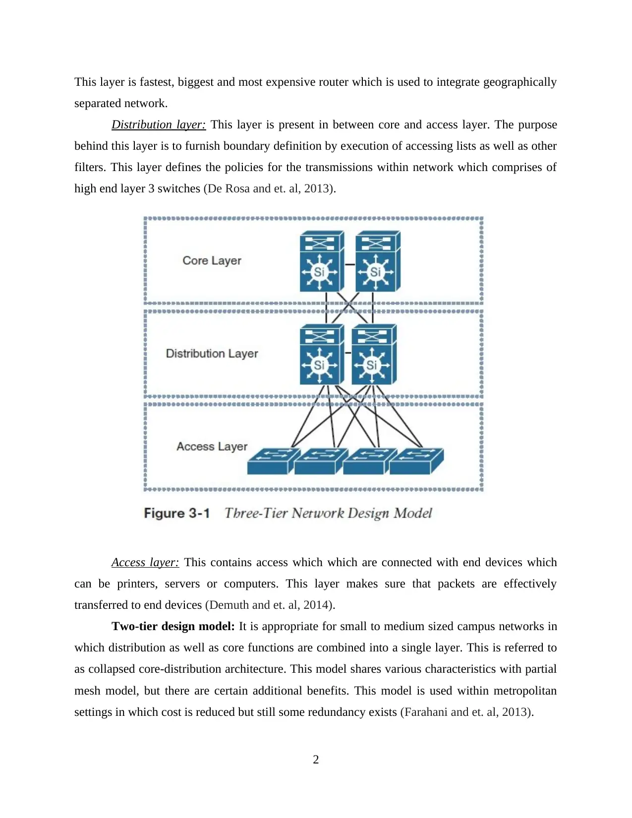
This layer is fastest, biggest and most expensive router which is used to integrate geographically
separated network.
Distribution layer: This layer is present in between core and access layer. The purpose
behind this layer is to furnish boundary definition by execution of accessing lists as well as other
filters. This layer defines the policies for the transmissions within network which comprises of
high end layer 3 switches (De Rosa and et. al, 2013).
Access layer: This contains access which which are connected with end devices which
can be printers, servers or computers. This layer makes sure that packets are effectively
transferred to end devices (Demuth and et. al, 2014).
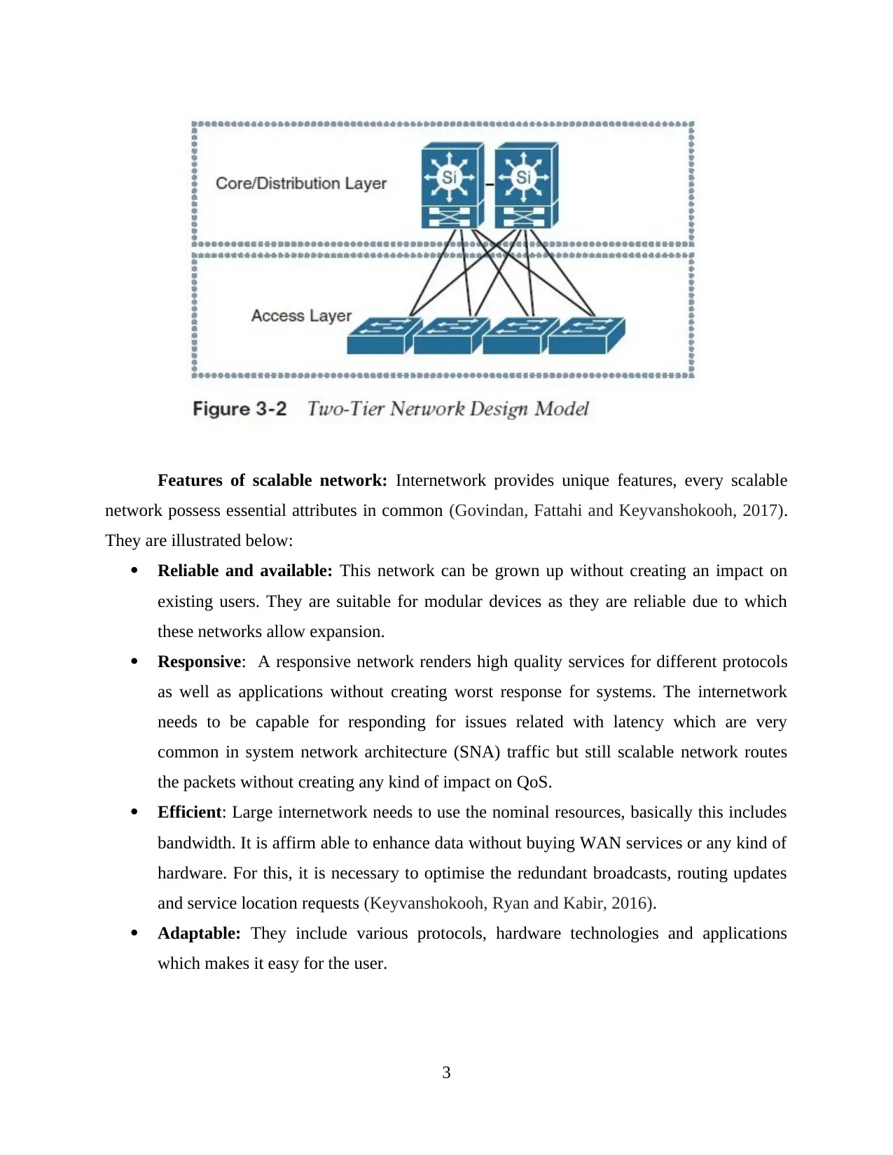
Two-tier design model: It is appropriate for small to medium sized campus networks in
which distribution as well as core functions are combined into a single layer. This is referred to
as collapsed core-distribution architecture. This model shares various characteristics with partial
mesh model, but there are certain additional benefits. This model is used within metropolitan
settings in which cost is reduced but still some redundancy exists (Farahani and et. al, 2013).
2
separated network.
Distribution layer: This layer is present in between core and access layer. The purpose
behind this layer is to furnish boundary definition by execution of accessing lists as well as other
filters. This layer defines the policies for the transmissions within network which comprises of
high end layer 3 switches (De Rosa and et. al, 2013).
Access layer: This contains access which which are connected with end devices which
can be printers, servers or computers. This layer makes sure that packets are effectively
transferred to end devices (Demuth and et. al, 2014).
Two-tier design model: It is appropriate for small to medium sized campus networks in
which distribution as well as core functions are combined into a single layer. This is referred to
as collapsed core-distribution architecture. This model shares various characteristics with partial
mesh model, but there are certain additional benefits. This model is used within metropolitan
settings in which cost is reduced but still some redundancy exists (Farahani and et. al, 2013).
2
Features of scalable network: Internetwork provides unique features, every scalable
network possess essential attributes in common (Govindan, Fattahi and Keyvanshokooh, 2017).
They are illustrated below:
Reliable and available: This network can be grown up without creating an impact on
existing users. They are suitable for modular devices as they are reliable due to which
these networks allow expansion.
Responsive: A responsive network renders high quality services for different protocols
as well as applications without creating worst response for systems. The internetwork
needs to be capable for responding for issues related with latency which are very
common in system network architecture (SNA) traffic but still scalable network routes
the packets without creating any kind of impact on QoS.
Efficient: Large internetwork needs to use the nominal resources, basically this includes
bandwidth. It is affirm able to enhance data without buying WAN services or any kind of
hardware. For this, it is necessary to optimise the redundant broadcasts, routing updates
and service location requests (Keyvanshokooh, Ryan and Kabir, 2016).
Adaptable: They include various protocols, hardware technologies and applications
which makes it easy for the user.
3
⊘ This is a preview!⊘
Do you want full access?
Subscribe today to unlock all pages.
Trusted by 1+ million students worldwide
Accessible but secure: This network enables multiple connections by making use of
switched services, dial up and dedicated services while maintaining the integrity of
network (Kim, 2014).
Rich set of features are provided by The CISCO IOS which renders network scalability.
Above the major features of scalable network are provided which helps people to make
optimum use of bandwidth without influencing quality of services.
P2 Discuss bandwidth, load and redundancy issues within LAN and solution with reference to
layer.
Network redundancy refers to process by which alternate or additional instances of
equipments, communication mediums and instances of network devices are installed within
network infrastructure. It ensures the availability of network devices if path fails and is
unavailable. Basically, it provides a backup if any networking devices fails.
LAN redundancy: It allows two physical network connections among client and server to
be used within networking and aids in rendering network path for the identical process data. If
connection over single network path is lost then network automatically fails in other paths
(Larsen and Urry, 2016).
Data link layer establish node to node delivery of the packets. In this case, it is ensured
that data transfer is error free. The most common scheme for network-level redundancy within
Ethernet switches is making use of multiple links among switches. When primary switch fails,
then the switches operating in parallel can take over. But this can lead to loops. For this one
switch can be disabled when normal operations are being carried out and it takes over when other
fails. IEEE 802.1D standard specifies STP (Spanning tree protocol) for implementation of
avoidance of loops as well as redundancy. This protocol provides faster recovery from failures.
Network layer works for transmitting data from one host to the other within various networks.
This layer ensures that packets are being transferred from shortest path and number of routes are
available (Mahaboob Sheriff, Gunasekaran and Nachiappan, 2012). Resiliency and redundancy
are built up in this layer via usage of routing protocols. RIP (Routing information protocol) or
OSPF (Open shortest path first) protocols recover a network from failure through recalculations
of routes to destinations which were reached by failed link. Traffic can be forwarded after
4
Paraphrase This Document
Need a fresh take? Get an instant paraphrase of this document with our AI Paraphraser

routing tables were recalculated. BY this packets will resume flow between destination and
source after recovery (Mulder and Dekker, 2014). The layer 3 switch can make use of alternative
forwarding path. OSPF provide equal-cost multipath routing like forwarding packet over various
paths to same destination as long as cost associated with this same. During the normal
operations, routing protocols do not allow alternate routes.
5
M1 Analysis of router and switch redundancy protocols along with their effectiveness in scalable
network.
Router redundancy protocols renders automated allocation of accessible IP (Internet
Protocol) routers to active hosts. They enhances reliability as well as availability of routing paths
through default gateway selection within IP subnetwork. VRRP (Virtual router redundancy
protocol) can be utilised for creating virtual routers in which multiple routers are represented,
they are backup and master routers which acts as a group. Basically, VRRP is open standard
protocol which is being utilised to furnish redundancy within a network. An example can be
taken to understand this concept, suppose if physical router who is routing packets (in lieu of
virtual router) fails then other physical router will automatically replace them. With respect to
scalability when a device fails then other device will start working this means that work will not
be hampered. Along with this, it will also provide scalability as various devices can be attached
with router.
Virtual switch redundancy protocols is a proprietary tool which furnish redundancy along
with sub-second failover within layer 3 and layer 2 mesh topologies. These devices provides
more backup space for systems. Suppose if any of the working devices becomes unavailable then
the backup can be utilised for furnishing services over active device and keep on forwarding
traffic within a network. Scalability in this aspect is also applicable as there are different
switches which can be used to automatically when anyone of physical devices fails. They
provide backup services and becomes new master along with this all VRID VLAN ports are set
to blocking state.
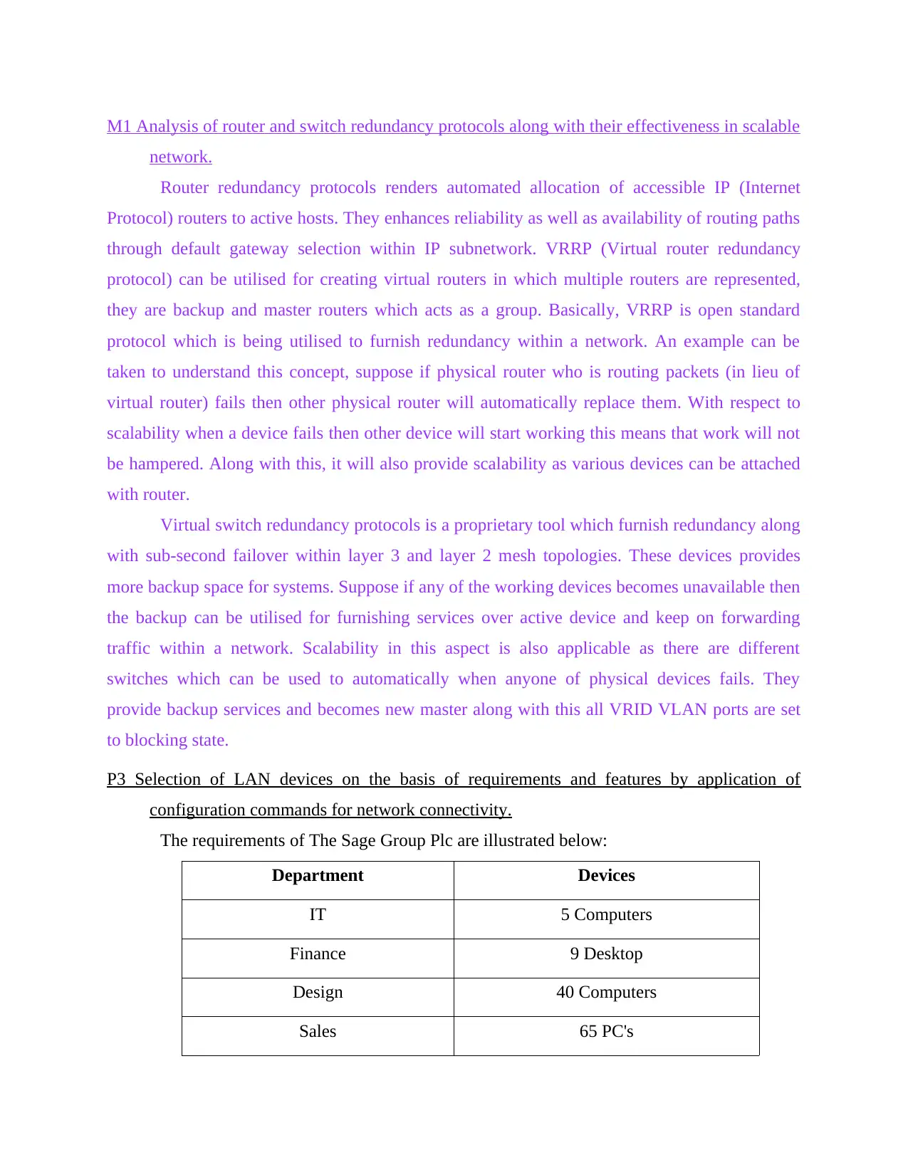
P3 Selection of LAN devices on the basis of requirements and features by application of
configuration commands for network connectivity.
The requirements of The Sage Group Plc are illustrated below:
Department Devices
IT 5 Computers
Finance 9 Desktop
Design 40 Computers
Sales 65 PC's
network.
Router redundancy protocols renders automated allocation of accessible IP (Internet
Protocol) routers to active hosts. They enhances reliability as well as availability of routing paths
through default gateway selection within IP subnetwork. VRRP (Virtual router redundancy
protocol) can be utilised for creating virtual routers in which multiple routers are represented,
they are backup and master routers which acts as a group. Basically, VRRP is open standard
protocol which is being utilised to furnish redundancy within a network. An example can be
taken to understand this concept, suppose if physical router who is routing packets (in lieu of
virtual router) fails then other physical router will automatically replace them. With respect to
scalability when a device fails then other device will start working this means that work will not
be hampered. Along with this, it will also provide scalability as various devices can be attached
with router.
Virtual switch redundancy protocols is a proprietary tool which furnish redundancy along
with sub-second failover within layer 3 and layer 2 mesh topologies. These devices provides
more backup space for systems. Suppose if any of the working devices becomes unavailable then
the backup can be utilised for furnishing services over active device and keep on forwarding
traffic within a network. Scalability in this aspect is also applicable as there are different
switches which can be used to automatically when anyone of physical devices fails. They
provide backup services and becomes new master along with this all VRID VLAN ports are set
to blocking state.
P3 Selection of LAN devices on the basis of requirements and features by application of
configuration commands for network connectivity.
The requirements of The Sage Group Plc are illustrated below:
Department Devices
IT 5 Computers
Finance 9 Desktop
Design 40 Computers
Sales 65 PC's
⊘ This is a preview!⊘
Do you want full access?
Subscribe today to unlock all pages.
Trusted by 1+ million students worldwide

Servers (DNS, web, email and file) 4 Servers
Each of these departments have a printer. The private address which will be used by The Sage
Group Plc is 192.168.1.0/24 and for other branches IP address is 192.168.168.0/24. Apart from
this, WAN link IP address is 30.40.50.168/28.
To meet these demands switch and router can be used. Switch is a data link layer device
with a multi port bridge which have a buffer and design which enhance its efficiency and
performance (Özkır and Başlıgıl, 2012). It will also carry out error checking before data is being
sent. Router, routes packets depending upon IP addresses. Router can be used for connecting
WAN and LAN, as well as routing table is updated by which decisions can made with respect to
routing of data packets.
Configuration commands for network connectivity: Computers within The Sage Group Plc are
within network and requests are sent in form of packets from host to destination (Sansò and
Soriano, 2012). For this there are various network configuration commands they are illustrated
below:
I. Packet internet groper (Ping): This make sure that computer can interact with a peculiar
device within a network (Simmons, 2014). This command renders details like number of packets
transmitted, received and time taken by packet to return. Example
a. For ensuring network connection
ping 192.168.1.21
This will ensure that this IP address is connected with network or not.
b. Measure time taken by packets
ping google.com
This will measure the time taken by packets for returning to find out speed of connection.
ii. nslookup: It is a network administration command line tool which is used for querying DNS
to attain IP address mapping. Like
nslookup facebook.com
This command will send query to DNS to fetch domain name from DNS records and IP
address for the same.
iii. traceroute: This command gives the route of packet and is used to identify path in which
packets travel. Example
2
Paraphrase This Document
Need a fresh take? Get an instant paraphrase of this document with our AI Paraphraser

traceroute www.google.com
This will return number of hops taken to reach at destination, gives list of hosts by which
packets travel to the destination.
iv. netstat: Network statistics display the routing table , status of ports, connection information,
etc. Example
netstat
It will display content of files defined within linux file system.
v. Arp: Address resolution protocol displays and modify cache which includes IP address
mapping to MAC address (Soleimani and Govindan, 2014). Example
arp
This will return the MAC address which is related with an IP address.
P4 Implementation of LAN design within Layer 2 and Layer 3 redundancy by making use of
router and switch redundancy protocols.
Layer 2: Data link layer establish node to node delivery of the packets. In this case, it is
ensured that data transfer is error free. The most common scheme for network-level redundancy
within Ethernet switches is making use of multiple links among switches (Szigeti and et. al,
2013). When primary switch fails, then the switches operating in parallel can take over. But this
can lead to loops. For this one switch can be disabled when normal operations are being carried
out and it takes over when other fails. IEEE 802.1D standard specifies STP (Spanning tree
protocol) for implementation of avoidance of loops as well as redundancy. This protocol
provides faster recovery from failures (Source: Redundancy: Choosing the Right Option for Net
Designs, 2019).
.
3
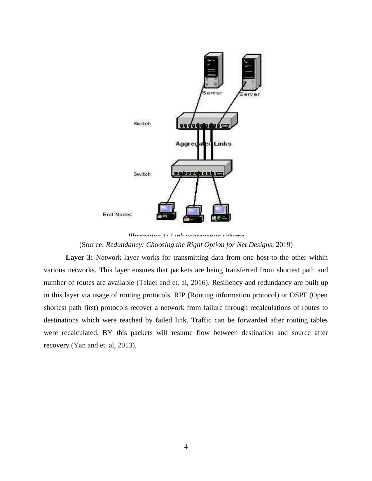
(Source: Redundancy: Choosing the Right Option for Net Designs, 2019)
Layer 3: Network layer works for transmitting data from one host to the other within
various networks. This layer ensures that packets are being transferred from shortest path and
number of routes are available (Talaei and et. al, 2016). Resiliency and redundancy are built up
in this layer via usage of routing protocols. RIP (Routing information protocol) or OSPF (Open
shortest path first) protocols recover a network from failure through recalculations of routes to
destinations which were reached by failed link. Traffic can be forwarded after routing tables
were recalculated. BY this packets will resume flow between destination and source after
recovery (Yan and et. al, 2013).
4
Illustration 1: Link aggregation scheme
⊘ This is a preview!⊘
Do you want full access?
Subscribe today to unlock all pages.
Trusted by 1+ million students worldwide
1 out of 24
Related Documents

Your All-in-One AI-Powered Toolkit for Academic Success.
+13062052269
info@desklib.com
Available 24*7 on WhatsApp / Email
![[object Object]](/_next/static/media/star-bottom.7253800d.svg)
Unlock your academic potential
Copyright © 2020–2026 A2Z Services. All Rights Reserved. Developed and managed by ZUCOL.