CVA005: Analysis and Design of Trusses vs. Beams in Structures
VerifiedAdded on 2023/04/19
|30
|6718
|130
Report
AI Summary
This report analyzes the structural behavior of trusses and beams through calculations and comparisons. Task 1 involves selecting the best beam cross-section based on bending stress analysis. Task 2 focuses on a simply supported overhang beam, calculating external forces, drawing shear force and bending moment diagrams, and determining maximum normal stress. Task 3 calculates external reactions and internal forces within a steel truss. Finally, Task 4 determines a suitable diameter for truss elements and compares the beam and truss designs to identify the most convenient solution.
Trusses vs. Beams: Analysis and Design 1
TRUSSES VS. BEAMS: ANALYSIS AND DESIGN
Name
Course
Professor
University
City/state
Date
TRUSSES VS. BEAMS: ANALYSIS AND DESIGN
Name
Course
Professor
University
City/state
Date
Paraphrase This Document
Need a fresh take? Get an instant paraphrase of this document with our AI Paraphraser
Trusses vs. Beams: Analysis and Design 2
Table of Contents
1. Introduction.......................................................................................................................................3
2. Task 1.................................................................................................................................................3
2.1. Neutral axis................................................................................................................................4
2.2. Moment of inertia......................................................................................................................6
2.3. Maximum bending stress..........................................................................................................8
3. Task 2.................................................................................................................................................9
3.1. Support reactions.......................................................................................................................9
3.2. Moments...................................................................................................................................10
4. Task 3...............................................................................................................................................15
5. Task 4...............................................................................................................................................24
5.1. Suitable diameter for the truss elements................................................................................24
5.2. Most convenient design solution.............................................................................................25
6. Conclusion........................................................................................................................................27
References................................................................................................................................................29
Trusses vs. Beams: Analysis and Design 3
1. Introduction
The strength, stability and safety of a structure largely depends on the design of its
elements. The design entails the geometric properties and materials of the elements. These
elements have to be designed such that they are compatible and create an integrated structure.
The aim of this report is to analyze the structural behavior of simple structural elements – trusses
and beams, by performing different calculations. The report contains four tasks each with a
different question. The first task involves analyzing three different cross sections of a beam and
selecting the one that would be nest for design purposes. The second task involves analyzing a
simply supported overhang beam subjected to a uniformly distributed load by calculating its
external forces, drawing the shear force and bending moment diagrams, and calculating the
maximum normal stress that would be acting on the beam. The third task involves determining
external reactions and internal forces of in all members of a steel truss. The fourth task involves
determining a suitable diameter for the truss elements, and determining the most convenient
design solution between the beam in task 2 and the truss in task 3.
2. Task 1
Since the three cross sections have the same cross-sectional area and total height, and
they are subjected to the same bending load, the most suitable approach of determining the one
that would be the best design option for the beam is calculating the maximum bending stress in
each cross section. This will help in determining the capability of each cross section to withstand
the maximum bending moment of the beam.
The maximum bending stress of a beam is calculated using equation 1 below
σ max ¿ Mc
I …………………………………………… (1)
⊘ This is a preview!⊘
Do you want full access?
Subscribe today to unlock all pages.
Trusted by 1+ million students worldwide
Trusses vs. Beams: Analysis and Design 4
Where σmax is the maximum bending moment; c is the vertical distance between the neutral axis
and the topmost or bottommost part of the beam (where the beam can experience either tension
or compression force), and I is the second moment of area (moment of inertia) of the beam.
In this case, the three cross sections have equal cross sectional area and total height hence the
maximum bending moment will also be the same in all the cross sections. However, the values of
c and I will be varied for each cross section because they have different geometries. Thus it is
important to calculate the values of c and I for each cross section.
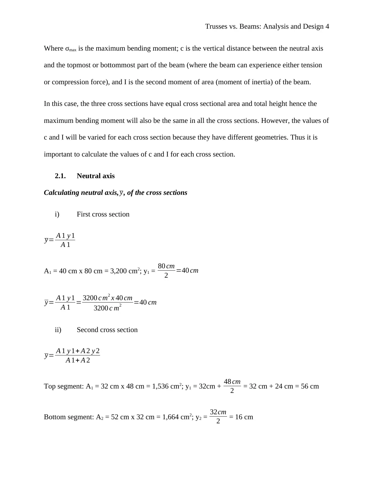
2.1. Neutral axis
Calculating neutral axis, y, of the cross sections
i) First cross section
y= A 1 y 1
A 1
A1 = 40 cm x 80 cm = 3,200 cm2; y1 = 80 cm
2 =40 cm
y= A 1 y 1
A 1 = 3200 c m2 x 40 cm
3200 c m2 =40 cm
ii) Second cross section
y= A 1 y 1+ A 2 y 2
A 1+ A 2
Top segment: A1 = 32 cm x 48 cm = 1,536 cm2; y1 = 32cm + 48 cm
2 = 32 cm + 24 cm = 56 cm
Bottom segment: A2 = 52 cm x 32 cm = 1,664 cm2; y2 = 32cm
2 = 16 cm
Where σmax is the maximum bending moment; c is the vertical distance between the neutral axis
and the topmost or bottommost part of the beam (where the beam can experience either tension
or compression force), and I is the second moment of area (moment of inertia) of the beam.
In this case, the three cross sections have equal cross sectional area and total height hence the
maximum bending moment will also be the same in all the cross sections. However, the values of
c and I will be varied for each cross section because they have different geometries. Thus it is
important to calculate the values of c and I for each cross section.
2.1. Neutral axis
Calculating neutral axis, y, of the cross sections
i) First cross section
y= A 1 y 1
A 1
A1 = 40 cm x 80 cm = 3,200 cm2; y1 = 80 cm
2 =40 cm
y= A 1 y 1
A 1 = 3200 c m2 x 40 cm
3200 c m2 =40 cm
ii) Second cross section
y= A 1 y 1+ A 2 y 2
A 1+ A 2
Top segment: A1 = 32 cm x 48 cm = 1,536 cm2; y1 = 32cm + 48 cm
2 = 32 cm + 24 cm = 56 cm
Bottom segment: A2 = 52 cm x 32 cm = 1,664 cm2; y2 = 32cm
2 = 16 cm
Paraphrase This Document
Need a fresh take? Get an instant paraphrase of this document with our AI Paraphraser
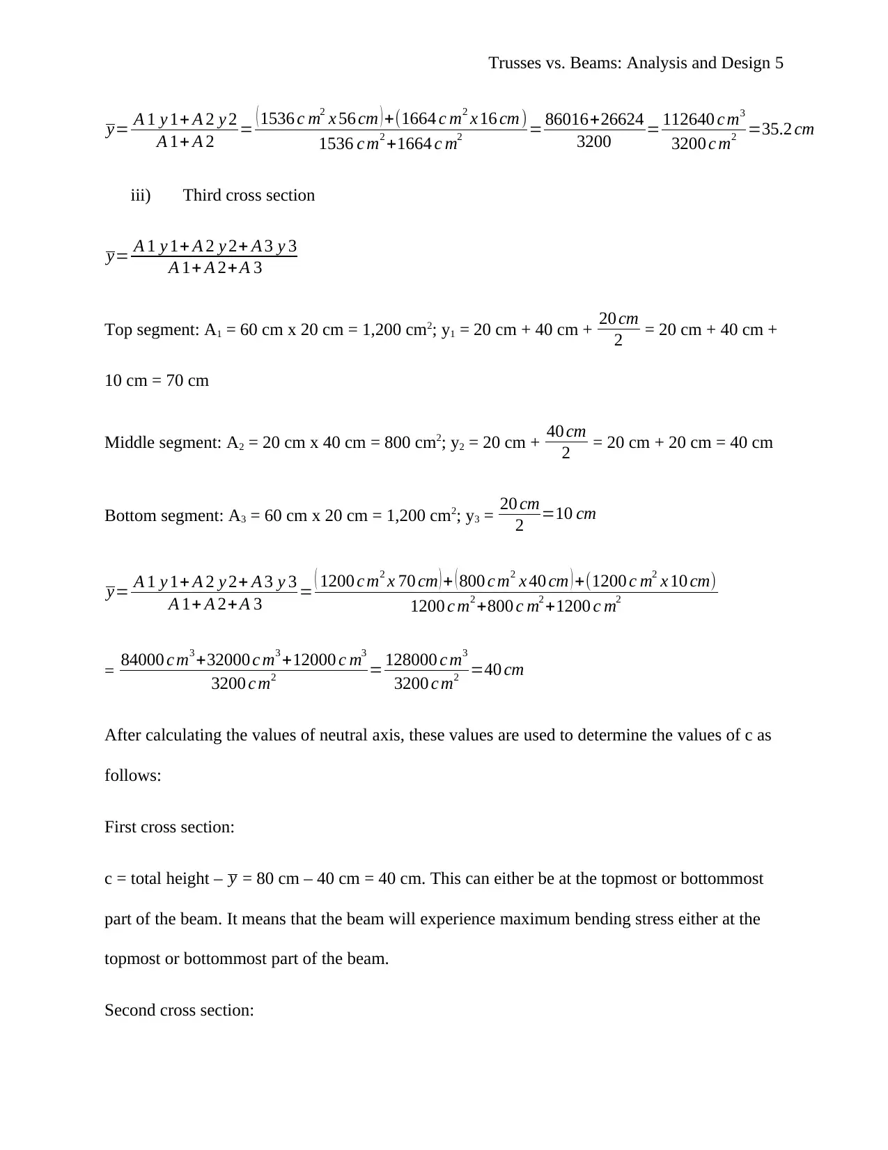
Trusses vs. Beams: Analysis and Design 5
y= A 1 y 1+ A 2 y 2
A 1+ A 2 = ( 1536 c m2 x 56 cm ) +(1664 c m2 x 16 cm )
1536 c m2 +1664 c m2 = 86016+26624
3200 = 112640 c m3
3200 c m2 =35.2 cm
iii) Third cross section
y= A 1 y 1+ A 2 y 2+ A 3 y 3
A 1+ A 2+A 3
Top segment: A1 = 60 cm x 20 cm = 1,200 cm2; y1 = 20 cm + 40 cm + 20 cm
2 = 20 cm + 40 cm +
10 cm = 70 cm
Middle segment: A2 = 20 cm x 40 cm = 800 cm2; y2 = 20 cm + 40 cm
2 = 20 cm + 20 cm = 40 cm
Bottom segment: A3 = 60 cm x 20 cm = 1,200 cm2; y3 = 20 cm
2 =10 cm
y= A 1 y 1+ A 2 y 2+ A 3 y 3
A 1+ A 2+A 3 = ( 1200 c m2 x 70 cm ) + ( 800 c m2 x 40 cm ) +(1200 c m2 x 10 cm)
1200 c m2 +800 c m2 +1200 c m2
= 84000 c m3 +32000 c m3 +12000 c m3
3200 c m2 = 128000 c m3
3200 c m2 =40 cm
After calculating the values of neutral axis, these values are used to determine the values of c as
follows:
First cross section:
c = total height – y = 80 cm – 40 cm = 40 cm. This can either be at the topmost or bottommost
part of the beam. It means that the beam will experience maximum bending stress either at the
topmost or bottommost part of the beam.
Second cross section:
Trusses vs. Beams: Analysis and Design 6
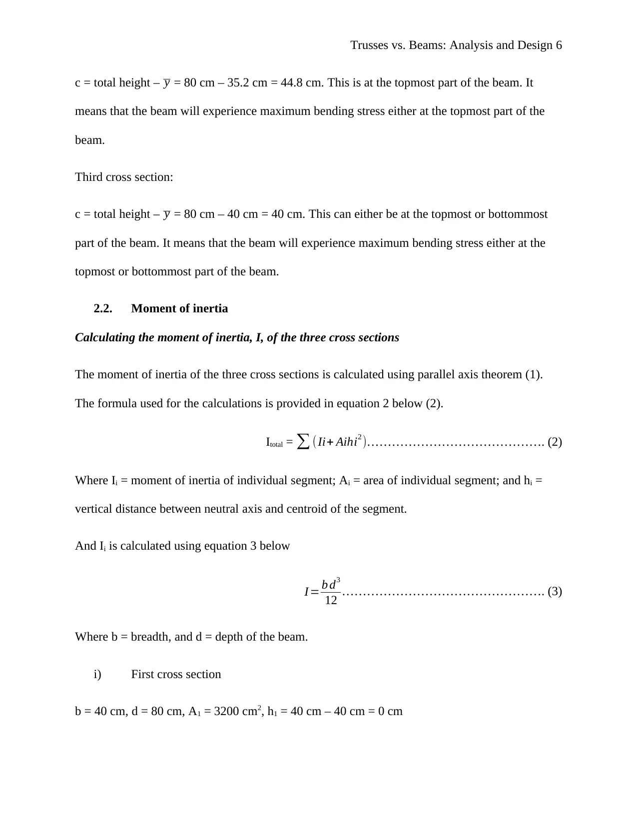
c = total height – y = 80 cm – 35.2 cm = 44.8 cm. This is at the topmost part of the beam. It
means that the beam will experience maximum bending stress either at the topmost part of the
beam.
Third cross section:
c = total height – y = 80 cm – 40 cm = 40 cm. This can either be at the topmost or bottommost
part of the beam. It means that the beam will experience maximum bending stress either at the
topmost or bottommost part of the beam.
2.2. Moment of inertia
Calculating the moment of inertia, I, of the three cross sections
The moment of inertia of the three cross sections is calculated using parallel axis theorem (1).
The formula used for the calculations is provided in equation 2 below (2).
Itotal = ∑ (Ii+ Aihi2 )……………………………………. (2)
Where Ii = moment of inertia of individual segment; Ai = area of individual segment; and hi =
vertical distance between neutral axis and centroid of the segment.
And Ii is calculated using equation 3 below
I = b d3
12 …………………………………………. (3)
Where b = breadth, and d = depth of the beam.
i) First cross section
b = 40 cm, d = 80 cm, A1 = 3200 cm2, h1 = 40 cm – 40 cm = 0 cm
⊘ This is a preview!⊘
Do you want full access?
Subscribe today to unlock all pages.
Trusted by 1+ million students worldwide

Trusses vs. Beams: Analysis and Design 7
I 1=( 40 x 803
12 )+ ( 3200 x 02 ) =1.707 x 10⁶ c m4
ii) Second cross section
Top segment:
b = 32 cm, d = 48 cm, A1 = 1536 cm2, h1 = 56 cm – 35.2 cm = 20.8 cm
I 1=( 32 x 483
12 ) + ( 1536 x 20.82 ) =294,912c m4 +664,535.04 c m4=959,447.04 c m4
Bottom segment:
b = 52 cm, d = 32 cm, A2 = 1664 cm2, h2 = 35.2 cm – 16 cm = 19.2 cm
I 2=( 52 x 323
12 ) + ( 1664 x 19.22 ) =141,994.67 c m4 + 613,416.96 c m4 =755,411.63 c m4
Itotal = I1 + I2 = 959,447.04 cm4 + 755,411.63 cm4 = 1714858.67 cm4 = 1.715 x 106 cm4
iii) Third cross section
Top segment:
b = 60 cm, d = 20 cm, A1 = 1200 cm2, h1 = 70 cm – 40 cm = 30 cm
I 1=( 60 x 203
12 ) + ( 1200 x 302 ) =40,000 c m4 +1080000 c m4=1,120,000 c m4
Middle segment:
b = 20 cm, d = 40 cm, A2 = 800 cm2, h2 = 40 cm – 40 cm = 0 cm
I 2=( 20 x 403
12 ) + ( 800 x 02 )=106,666.67 c m4 +0 c m4=106,666.67 c m4
Paraphrase This Document
Need a fresh take? Get an instant paraphrase of this document with our AI Paraphraser
Trusses vs. Beams: Analysis and Design 8
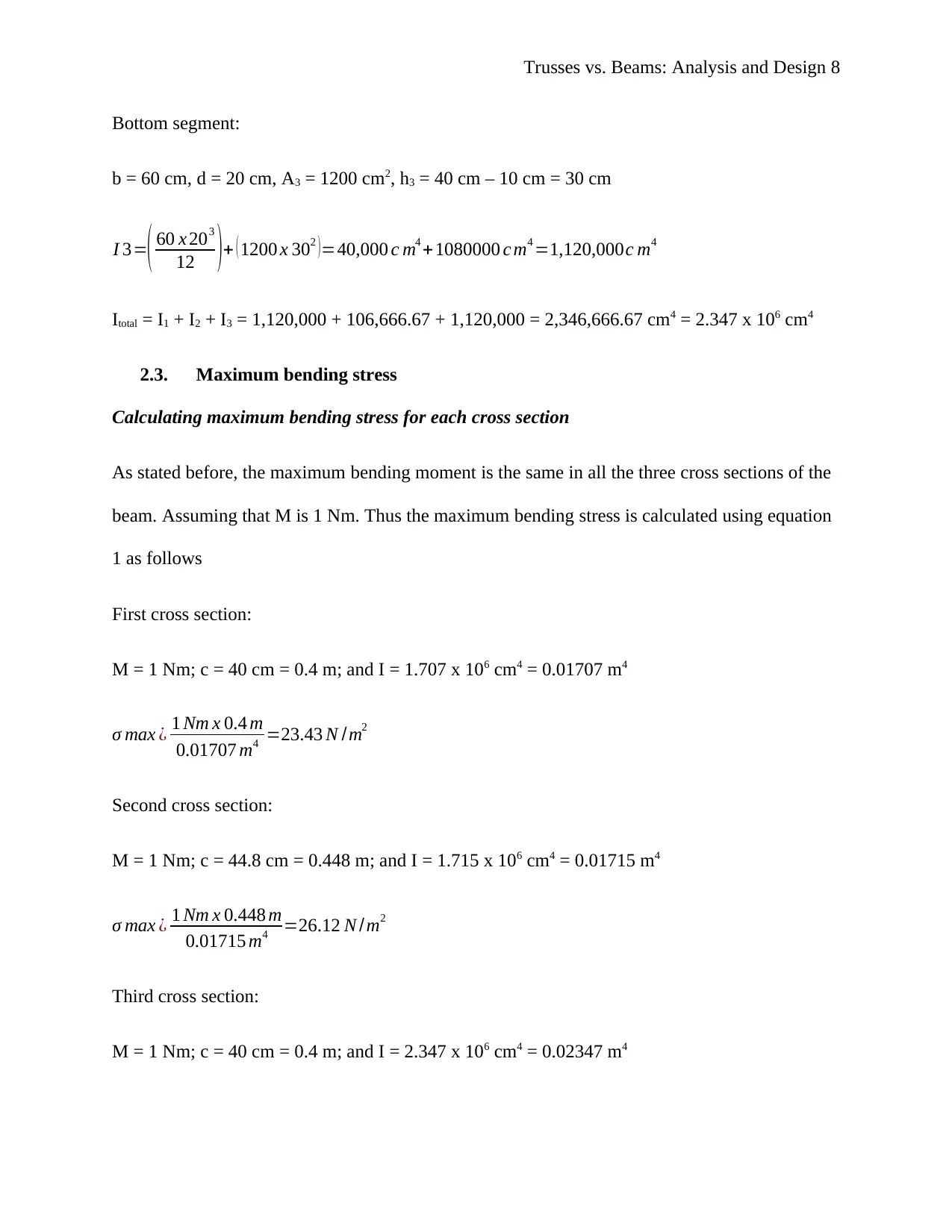
Bottom segment:
b = 60 cm, d = 20 cm, A3 = 1200 cm2, h3 = 40 cm – 10 cm = 30 cm
I 3=( 60 x 203
12 )+ ( 1200 x 302 ) =40,000 c m4 +1080000 c m4 =1,120,000c m4
Itotal = I1 + I2 + I3 = 1,120,000 + 106,666.67 + 1,120,000 = 2,346,666.67 cm4 = 2.347 x 106 cm4
2.3. Maximum bending stress
Calculating maximum bending stress for each cross section
As stated before, the maximum bending moment is the same in all the three cross sections of the
beam. Assuming that M is 1 Nm. Thus the maximum bending stress is calculated using equation
1 as follows
First cross section:
M = 1 Nm; c = 40 cm = 0.4 m; and I = 1.707 x 106 cm4 = 0.01707 m4
σ max ¿ 1 Nm x 0.4 m
0.01707 m4 =23.43 N /m2
Second cross section:
M = 1 Nm; c = 44.8 cm = 0.448 m; and I = 1.715 x 106 cm4 = 0.01715 m4
σ max ¿ 1 Nm x 0.448 m
0.01715 m4 =26.12 N /m2
Third cross section:
M = 1 Nm; c = 40 cm = 0.4 m; and I = 2.347 x 106 cm4 = 0.02347 m4
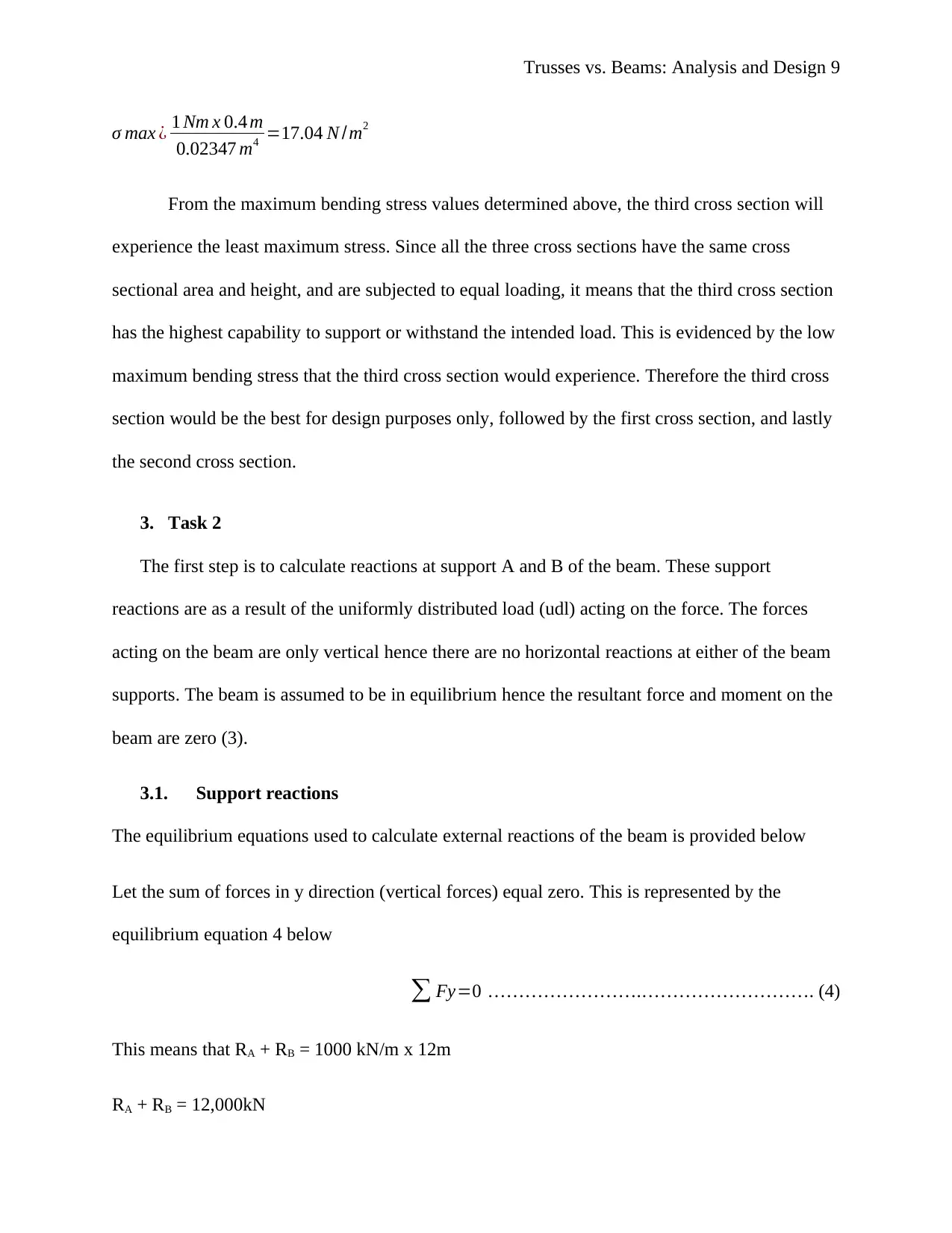
Trusses vs. Beams: Analysis and Design 9
σ max ¿ 1 Nm x 0.4 m
0.02347 m4 =17.04 N /m2
From the maximum bending stress values determined above, the third cross section will
experience the least maximum stress. Since all the three cross sections have the same cross
sectional area and height, and are subjected to equal loading, it means that the third cross section
has the highest capability to support or withstand the intended load. This is evidenced by the low
maximum bending stress that the third cross section would experience. Therefore the third cross
section would be the best for design purposes only, followed by the first cross section, and lastly
the second cross section.
3. Task 2
The first step is to calculate reactions at support A and B of the beam. These support
reactions are as a result of the uniformly distributed load (udl) acting on the force. The forces
acting on the beam are only vertical hence there are no horizontal reactions at either of the beam
supports. The beam is assumed to be in equilibrium hence the resultant force and moment on the
beam are zero (3).
3.1. Support reactions
The equilibrium equations used to calculate external reactions of the beam is provided below
Let the sum of forces in y direction (vertical forces) equal zero. This is represented by the
equilibrium equation 4 below
∑ Fy=0 …………………….………………………. (4)
This means that RA + RB = 1000 kN/m x 12m
RA + RB = 12,000kN
⊘ This is a preview!⊘
Do you want full access?
Subscribe today to unlock all pages.
Trusted by 1+ million students worldwide
Trusses vs. Beams: Analysis and Design 10
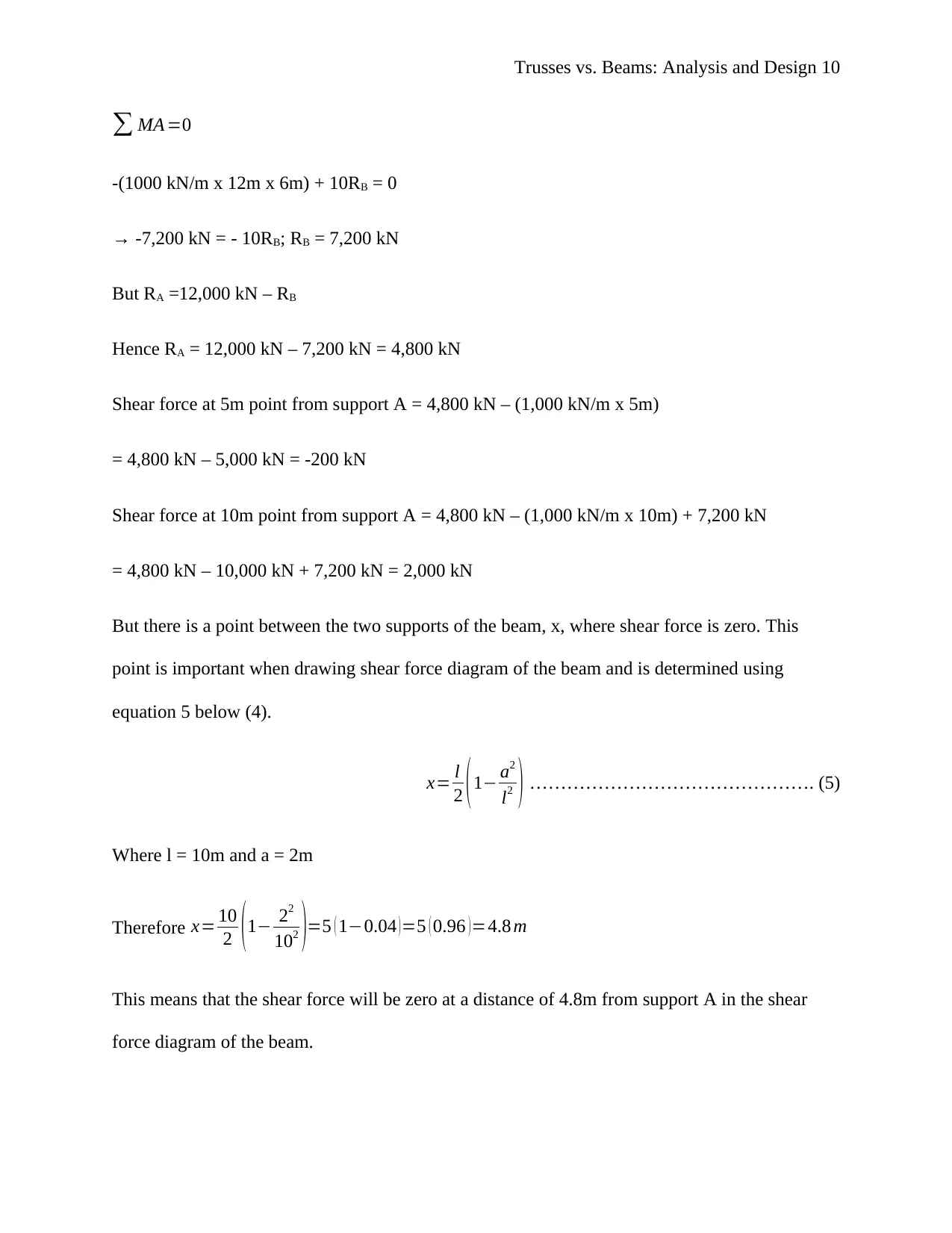
∑ MA =0
-(1000 kN/m x 12m x 6m) + 10RB = 0
→ -7,200 kN = - 10RB; RB = 7,200 kN
But RA =12,000 kN – RB
Hence RA = 12,000 kN – 7,200 kN = 4,800 kN
Shear force at 5m point from support A = 4,800 kN – (1,000 kN/m x 5m)
= 4,800 kN – 5,000 kN = -200 kN
Shear force at 10m point from support A = 4,800 kN – (1,000 kN/m x 10m) + 7,200 kN
= 4,800 kN – 10,000 kN + 7,200 kN = 2,000 kN
But there is a point between the two supports of the beam, x, where shear force is zero. This
point is important when drawing shear force diagram of the beam and is determined using
equation 5 below (4).
x= l
2 ( 1− a2
l2 ) ………………………………………. (5)
Where l = 10m and a = 2m
Therefore x= 10
2 ( 1− 22
102 )=5 ( 1−0.04 ) =5 ( 0.96 ) =4.8 m
This means that the shear force will be zero at a distance of 4.8m from support A in the shear
force diagram of the beam.
Paraphrase This Document
Need a fresh take? Get an instant paraphrase of this document with our AI Paraphraser
Trusses vs. Beams: Analysis and Design 11
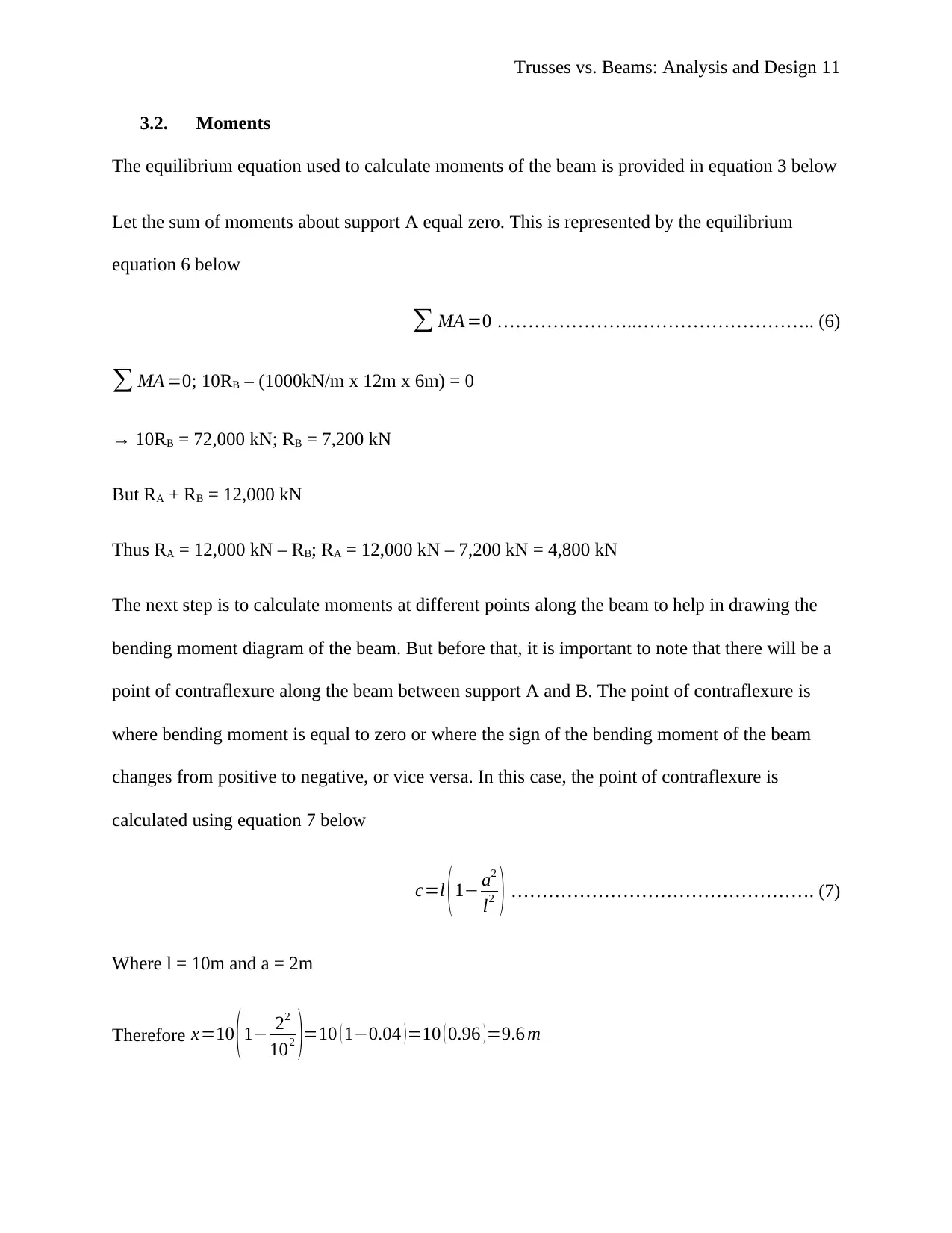
3.2. Moments
The equilibrium equation used to calculate moments of the beam is provided in equation 3 below
Let the sum of moments about support A equal zero. This is represented by the equilibrium
equation 6 below
∑ MA =0 …………………..……………………….. (6)
∑ MA =0; 10RB – (1000kN/m x 12m x 6m) = 0
→ 10RB = 72,000 kN; RB = 7,200 kN
But RA + RB = 12,000 kN
Thus RA = 12,000 kN – RB; RA = 12,000 kN – 7,200 kN = 4,800 kN
The next step is to calculate moments at different points along the beam to help in drawing the
bending moment diagram of the beam. But before that, it is important to note that there will be a
point of contraflexure along the beam between support A and B. The point of contraflexure is
where bending moment is equal to zero or where the sign of the bending moment of the beam
changes from positive to negative, or vice versa. In this case, the point of contraflexure is
calculated using equation 7 below
c=l (1− a2
l2 ) …………………………………………. (7)
Where l = 10m and a = 2m
Therefore x=10 ( 1− 22
102 )=10 ( 1−0.04 ) =10 ( 0.96 ) =9.6 m
Trusses vs. Beams: Analysis and Design 12
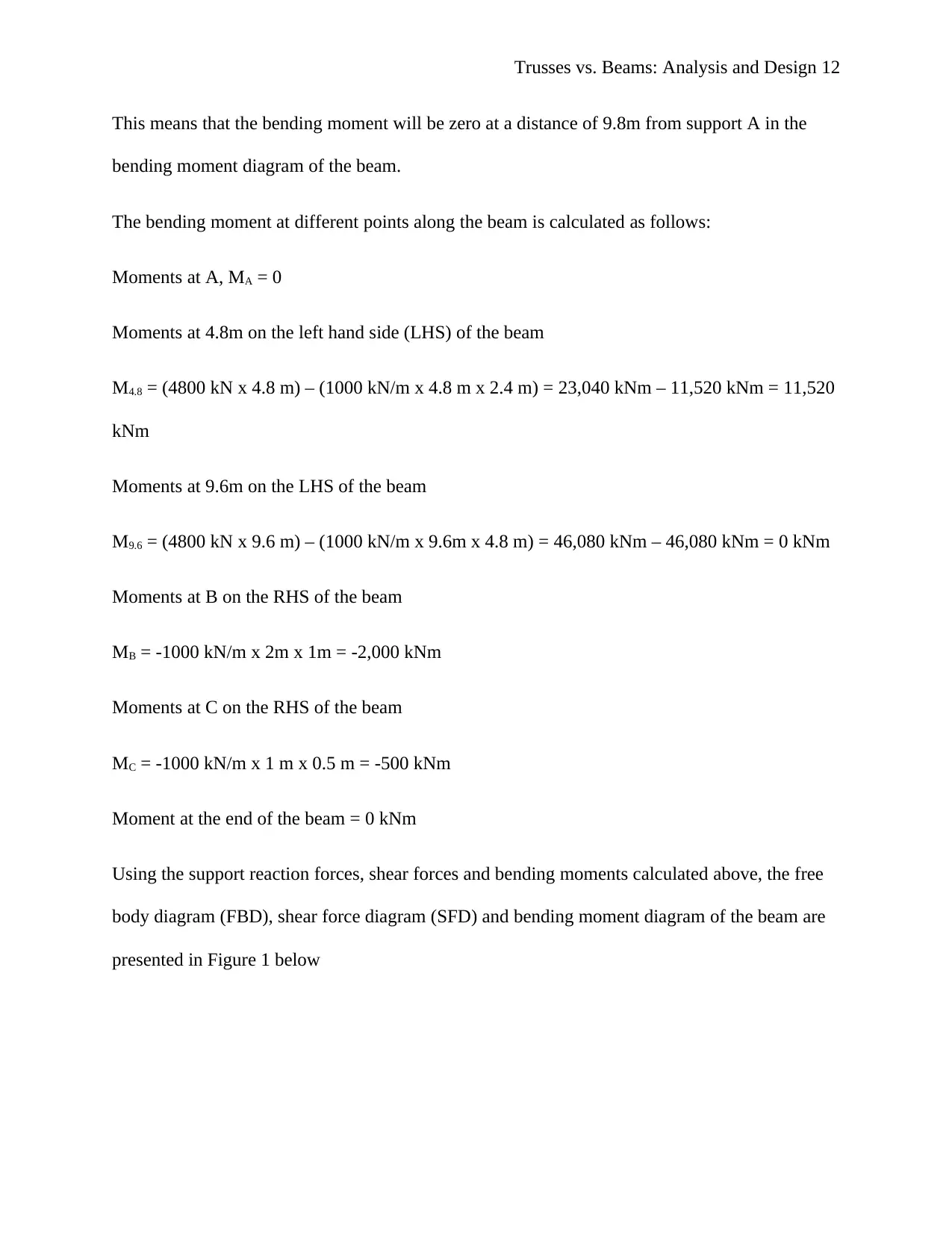
This means that the bending moment will be zero at a distance of 9.8m from support A in the
bending moment diagram of the beam.
The bending moment at different points along the beam is calculated as follows:
Moments at A, MA = 0
Moments at 4.8m on the left hand side (LHS) of the beam
M4.8 = (4800 kN x 4.8 m) – (1000 kN/m x 4.8 m x 2.4 m) = 23,040 kNm – 11,520 kNm = 11,520
kNm
Moments at 9.6m on the LHS of the beam
M9.6 = (4800 kN x 9.6 m) – (1000 kN/m x 9.6m x 4.8 m) = 46,080 kNm – 46,080 kNm = 0 kNm
Moments at B on the RHS of the beam
MB = -1000 kN/m x 2m x 1m = -2,000 kNm
Moments at C on the RHS of the beam
MC = -1000 kN/m x 1 m x 0.5 m = -500 kNm
Moment at the end of the beam = 0 kNm
Using the support reaction forces, shear forces and bending moments calculated above, the free
body diagram (FBD), shear force diagram (SFD) and bending moment diagram of the beam are
presented in Figure 1 below
⊘ This is a preview!⊘
Do you want full access?
Subscribe today to unlock all pages.
Trusted by 1+ million students worldwide
1 out of 30
Related Documents


Your All-in-One AI-Powered Toolkit for Academic Success.
+13062052269
info@desklib.com
Available 24*7 on WhatsApp / Email
![[object Object]](/_next/static/media/star-bottom.7253800d.svg)
Unlock your academic potential
Copyright © 2020–2026 A2Z Services. All Rights Reserved. Developed and managed by ZUCOL.