Performance Analysis of Shell and Tube Heat Exchanger Designs
VerifiedAdded on 2023/01/13
|20
|5770
|39
Project
AI Summary
This dissertation proposal investigates the impact of tube arrangement on the performance of shell and tube heat exchangers (STHEs). The study focuses on numerical analysis of thermal-hydraulic execution using three STHE configurations with triangular, rotated triangular, and combined tube layouts. The research aims to determine how different tube arrangements affect heat transfer and pressure drop, key performance indicators. The literature review covers STHE working principles, different tube layout patterns, and their influence on heat exchanger performance. The project includes research scope, methods, budget, timeline, team charter, and communication strategy. The study seeks to evaluate the working procedure of STHEs, determine different tube layout patterns, and analyze their influence on heat exchanger performance. The findings are expected to provide insights into optimizing STHE design for improved efficiency.

Dissertation Proposal
Paraphrase This Document
Need a fresh take? Get an instant paraphrase of this document with our AI Paraphraser
Abstract
Shell and tube heat exchangers are the most common type of heat transferrers and are able
for wide range of operating temperatures and pressures. Numerical analysis on thermal hydraulic
execution of three seats of shell and tube heat exchangers with diverse geometrical tube layout
structures fluctuations namely, triangular, rotated triangular and combined patterns were outlined
in the report, the outcomes from resolving the dominating cohesiveness, momentum and energy
equations displayed that bulk of the heat transfer and pressure drop generate at the time of cross-
flow of shell-fluid by the tube of bundles. Measurement of the executions of the heat transferrers
displayed that the STHE_T is more effectively followed by the STHE_C as they show higher
heat exchange constant than the STHE _RT for the similar pressure drop in the shell side.
Keywords:
Shell diameter, Fouling rate, Baffle Window, Cutting space, Thermal-hydraullic, Tube Layout
Table of Contents
Abstract............................................................................................................................................2
Keywords:........................................................................................................................................2
Topic: Effect of tube arrangement on the performance of shell and tube heat exchanger..............1
Chapter 1: Introduction....................................................................................................................1
Chapter 2: Literature Review...........................................................................................................2
Theme 1: Working procedure of shell and tube heat exchanger.................................................2
Theme 2: Different patterns of tube layout in heat exchanger devices.......................................3
Theme 3: Influence of tube layout pattern on performance of heat exchanger devices..............4
Chapter 3: Research Scope..............................................................................................................8
Significance of research...............................................................................................................8
Chapter 4: Research Method............................................................................................................9
Chapter 5: Project Budget, Resources and Time Line.....................................................................9
Project Budget.............................................................................................................................9
Resources.....................................................................................................................................9
Time Line...................................................................................................................................10
Chapter 6: Team Charter and Communication strategy................................................................11
Chapter 7: Summary......................................................................................................................12
REFERENCES..............................................................................................................................13
⊘ This is a preview!⊘
Do you want full access?
Subscribe today to unlock all pages.
Trusted by 1+ million students worldwide

Paraphrase This Document
Need a fresh take? Get an instant paraphrase of this document with our AI Paraphraser
Topic: Effect of tube arrangement on the performance of shell and tube heat
exchanger
Chapter 1: Introduction
A heat exchanger refers to a device which is used for transferring thermal energy at
different-different temperature between two or more fluids, within thermal contact (Abd, Kareem
and Naji, 2018). Such devices are mainly used in a range of engineering applications like
refrigeration, power generation, air-conditioning, space applications, waste heat recovery,
manufacturing and petrochemical industries etc. Therefore, heat exchangers devices can be
classified on the basis of transfer process, number of fluids, cross flow arrangement,
construction, surface compactness and heat transfer mechanisms. In context with Shell and Tube
Heat Exchangers (STHEs), these devices are known as most common types of heat exchanger
which is applicable for operating pressures and temperatures (Boukhadia and et. al., 2018). This
device consists of a shell i.e. a large pressure vessel having various hollow tubes which are fitted
inside in it. Along with this, it also consists baffles for directing the fluid flow as well as
supporting the tubes. For this purpose, baffles and tubes are assembled together with support of
rods and spacers, in different-different tube layout pattern (Du, Chen, Du and Cheng, 2019). But
different pattern of layout depends on number of fundamental issues like pressure drop, phase
change, compactness, accessibility regarding with mechanical cleaning and more. So, this would
highly influence the performance of not only shell but also on overall performance of STHE.
Therefore, to determine how much changes in tube layout pattern effect tube heat exchanger’s
performance, an investigation is done in present research.
Research aim: “To determine the effect of tube arrangement on the performance of shell
and tube heat exchanger”
Research Objectives:
To evaluate the working procedure of shell and tube heat exchanger
To determine different patterns of tube layout in heat exchanger devices
To analyse the way on which performance of shell and tube heat exchanger influence
Research Question:
How tube layout patterns influence the performance of shell and tube exchanger devices?
1
Chapter 2: Literature Review
Theme 1: Working procedure of shell and tube heat exchanger
A heat exchanger is used for transferring enthalpy (thermal energy) between a fluid and
solid surface, two or more fluids, etc. in thermal contact with varies in temperatures. Usually, in
such devices, work interactions and external heat not occurs. Therefore, typical applications in
heat exchangers involves the cooling or heating of a fluid stream as well as evaporation or might
be condensation of multi / single component fluid streams (Cai and et. al., 2019). The objectives
in other applications may include sterilize, distilled, pasteurize, concentrate, crystallize or more,
to control the fluid process or recovery / rejection of heat. In some heat exchangers, the fluids
that exchanges heat are might be in direct contact. While in most devices, heat transfer among
fluids are taken place by separating the wall transiently. According to the views of Brogan
(2020), the shell and tube heat exchanger is a type of heat exchanger in which fluid is transferred
into gaseous state. It also includes the process of heat exchanger that consist of both warmed and
chilled fluid (Dandotiya and Banker, 2017). In this, two fluids having different temperatures are
flow in this exchanger process. The fluid can be transform through tube walls. It consists of
pressure and temperature from which heat exchanger process occur. The one fluid flow outside
the tube but inside the shell while other fluid flows inside the tube. The shell and tube exchanger
mainly consist of various parts. These tubes are present in cylindrical form. In shell tube bundle
are present.
The tube bundle consists of tube sheets, baffles, tubes and tie rods, etc. in order to hold
bundle. In Front header, fluid enters inside of tube side. In rear header, the fluid leaves from this
part and returned to front header through multiple passes of tube side. The plenum is present on
the end of shell. This work by collecting or discharge the bundle of fluid. The baffles help in
removing barriers that occur at time of heat exchangers. As this improve regulation of shell by
creating turbulence in shell (Wang and et. al., 2017). It also decreases concentration of cold and
hot liquid. These are essential to work properly as it depends on proper functioning of heat
exchanger. In pressure, sometimes unexpected leak occurs but with pressure differential, leakage
or contamination of fluid can be prevented or minimized. The pressure has increased in tube
sheet so that leakage can be easily flow in cooling medium. This prevents from costly failures in
the process of fluid. In such type of exchanger, heat external and interactions between work are
not occur.
2
⊘ This is a preview!⊘
Do you want full access?
Subscribe today to unlock all pages.
Trusted by 1+ million students worldwide
Some heat exchangers consist of direct contact with fluid that exchange through heat.
While in others, walls are separately used in heat transfer process of fluid. In shell and tube heat
exchanger, liquid and gases both are used as fluids (Jiang and et. al., 2017). As per views of
Brogan (2020), this process is an efficient mode of energy conservation as large number of tubes
are used in which heat transfer occur at large number of area. In this, only one phase or single
phase used as heat exchangers for both liquid and gas on each side. The two fluids are used in
this heat exchanger process. One is for processing and other used as cooling medium. The small
diameter tubes are placed in shell in which process fluid are run after being cooled. The cooling
medium is present on outer part of shell. In order to keep function properly of, both fluid cooling
and process are regulated continuously in exchanger (Riahi and et. al., 2017). This exchanger
consists of small tubes which creates large surface area that help in proper functioning of shell
and tube exchanger. The cooling fluid is necessary to be choose in this exchanger as most plants
are require water supply.
There are some mediums that can be used as cooling fluid such as water, ethylene glycol
and propylene glycol in context of plants. The water is the most effective medium that are used
in this as it is easily available. The ethylene glycol has lower freezing point and higher boiling
point when it is mixed with water (SHELL AND TUBE HEAT EXCHANGERS, 2020). The
propylene glycol is less toxic and is used in coolant medium high as it reduces the issue of
coolant. This medium has qualities of freezing and boiling point and transfer of thermal heat.
There are some standard set in working of shell and tube exchanger. The Tubular exchanger
manufactures association set some standards that identify power of manufacturing of shell and
tube exchanger (Singh and Sarkar, 2018). With the help of this standard, workers get to know
standard of industry that can linked with heat exchanger as it can produce quality. In this, there
are three types of standards are included such as R, C and B. This exchanger can be used in
power plant or feed water.
Theme 2: Different patterns of tube layout in heat exchanger devices
Heat exchanger is basically a device which converts heat from one medium to another. It
is used in both heating and cooling processes (Abd, Kareem and Naji, 2018). Tube layouts in
heat exchanger devices refers to tubes which are located in a shell. There are four different types
of tube layouts in a heat exchanger devices such as square (90°), triangular (30°), rotated
triangular(60°)and rotated square (45°). Triangular patterns are used to provide greater heat
3
Paraphrase This Document
Need a fresh take? Get an instant paraphrase of this document with our AI Paraphraser
transfer as they make the fluid to flow in a turbulent manner around the piping. However, square
patterns of the tube layout are used where large fouling is experienced and cleaning is in a
constant manner (Geete and et. al., 2018). The prior function of tube layout in a heat exchanger
device is to involve large number of tubes in a shell in order to acquire maximum area for heat
transfer. A triangular pattern of tube layout will adapt more tubes in comparison to square or a
rotated square patterns. A triangular pattern is more often employed to produce high turbulence
and eventually leads to high amount of heat transfer. At the crucial tube pitch of 1.25 times the
tube O.D, it does not allow any mechanical cleaning of tubes, hence access lanes are not
available. Eventually, a triangular layout in the tube of a heat exchanger device is only limited to
clean shell side services (Kayabasi, Alperen and Kurt, 2019). As per the perspective of Chemical
Engineering World, (2013) it has been analysed that for the services which require mechanical
cleaning on the shell side, square patterns of the tube must be utilized. Access lanes are not
necessary for the chemical cleaning process, so it is important to use a triangular layout patten
for dirty shell side services to offer a suitable and an effective chemical cleaning. A triangular
pattern could be used for fixed tube sheets exchangers and square pattern is used for floating
head exchangers (Esapour and et. al., 2016). For U-tube exchangers a triangular pattern can be
utilise to provide a shell side stream and square pattern is used when it is dirty. Such different
patterns of tube layout in Shell and Tube Heat Exchangers would be helpful in effective heat
transfer. A tube layout angle is referred in context to the flow direction and is not linked with
vertical or horizontal reference line arrangement (He and et. al., 2016). For a given O.D ratio,
about 15% of the more tubes could be accommodated within a given shell diameter using a
triangular layout. High heat transfer is often link with this specific pattern of tube layout. Only
water jet cleaning is possible in this kind of layout. The effect of square pattern of tube on
performance of STHEs would be beneficial as it is used for dirty shell side services which
require mechanical cleaning method. It would probably increase the functioning of STHE and
would result in a effective heat transfer (Ma and et. al., 2017). It would be beneficial to use
rotated square pattern as square pattern may produce much amount of turbulence which may
leads to higher efficiency of transformation of pressure drop to heat transfer.
Theme 3: Influence of tube layout pattern on performance of heat exchanger devices
As per Tubular Exchangers Manufacturers Association (TEMA) standard, it has been
analysed that for tube layouts in the form of rotated triangular (with 60º angle) and triangular
4
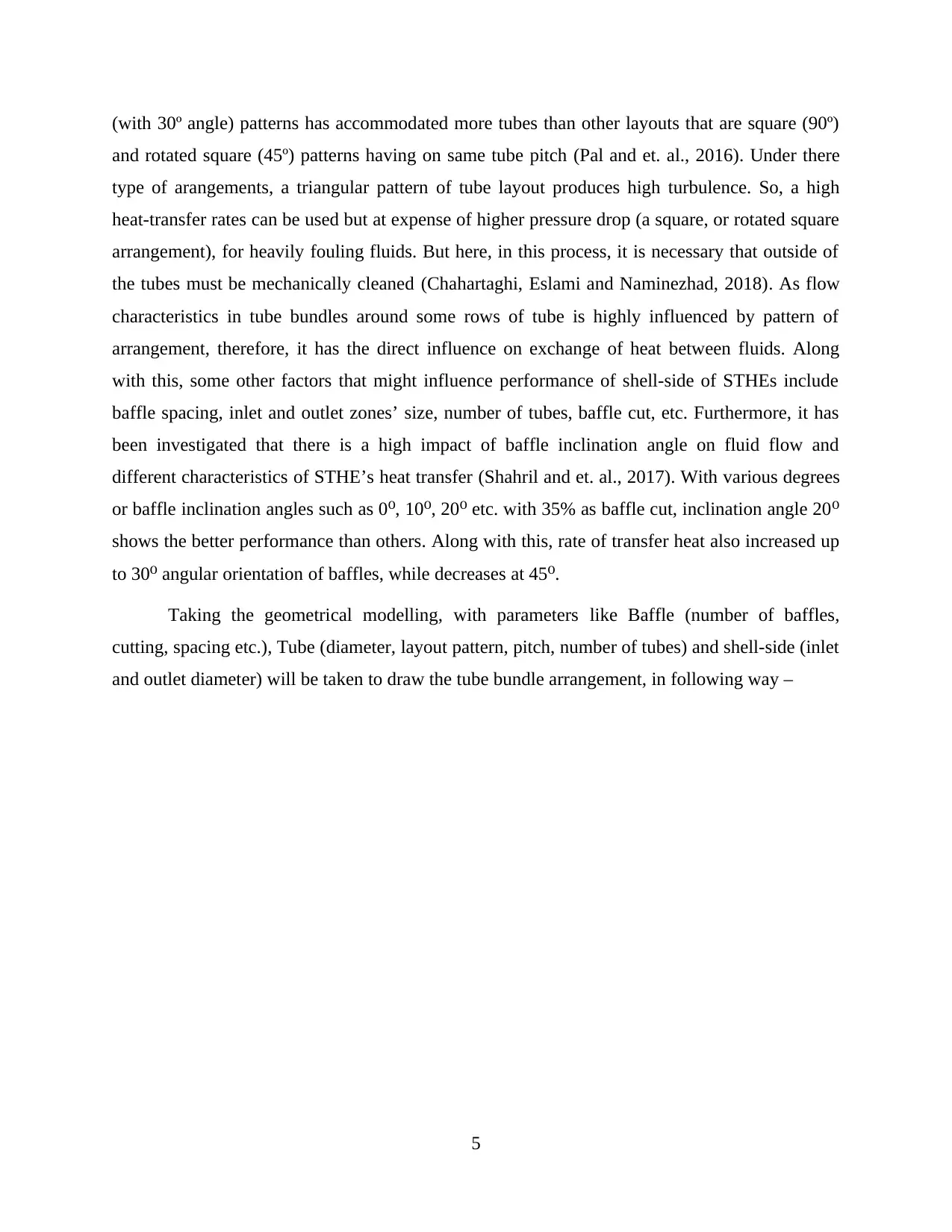
(with 30º angle) patterns has accommodated more tubes than other layouts that are square (90º)
and rotated square (45º) patterns having on same tube pitch (Pal and et. al., 2016). Under there
type of arangements, a triangular pattern of tube layout produces high turbulence. So, a high
heat-transfer rates can be used but at expense of higher pressure drop (a square, or rotated square
arrangement), for heavily fouling fluids. But here, in this process, it is necessary that outside of
the tubes must be mechanically cleaned (Chahartaghi, Eslami and Naminezhad, 2018). As flow
characteristics in tube bundles around some rows of tube is highly influenced by pattern of
arrangement, therefore, it has the direct influence on exchange of heat between fluids. Along
with this, some other factors that might influence performance of shell-side of STHEs include
baffle spacing, inlet and outlet zones’ size, number of tubes, baffle cut, etc. Furthermore, it has
been investigated that there is a high impact of baffle inclination angle on fluid flow and
different characteristics of STHE’s heat transfer (Shahril and et. al., 2017). With various degrees
or baffle inclination angles such as 0 , 10 , 20 etc. with 35% as baffle cut, inclination angle 20⁰ ⁰ ⁰ ⁰
shows the better performance than others. Along with this, rate of transfer heat also increased up
to 30 angular orientation of baffles, while decreases at 45 .⁰ ⁰
Taking the geometrical modelling, with parameters like Baffle (number of baffles,
cutting, spacing etc.), Tube (diameter, layout pattern, pitch, number of tubes) and shell-side (inlet
and outlet diameter) will be taken to draw the tube bundle arrangement, in following way –
5
⊘ This is a preview!⊘
Do you want full access?
Subscribe today to unlock all pages.
Trusted by 1+ million students worldwide
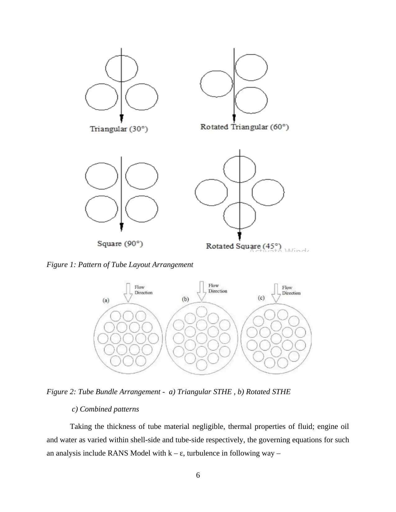
Figure 1: Pattern of Tube Layout Arrangement
Figure 2: Tube Bundle Arrangement - a) Triangular STHE , b) Rotated STHE
c) Combined patterns
Taking the thickness of tube material negligible, thermal properties of fluid; engine oil
and water as varied within shell-side and tube-side respectively, the governing equations for such
an analysis include RANS Model with k – ε, turbulence in following way –
6
Paraphrase This Document
Need a fresh take? Get an instant paraphrase of this document with our AI Paraphraser
∇.(𝛒u) = 0 as continuity equation … (i)
𝛒u. ∇ u = ∇. [-pI + (μ + μT ) ((∇u + (∇u)T ) – ⅔ (∇.u) I ) - ⅔ pkI ] + F as momentum
equation … (ii)
Using this momentum equation, turbulent KE equation will be –
𝛒u. ∇ k = ∇. [(μ + μT / σk) ∇k ] + μT P(u) – (⅔𝛒k)∇.u) – 𝛒ε …(iii)
Energy Equation –
𝛒Cp u. ∇ T = ∇ . (k ∇T) + Q
Under these equations, constants of RANS model –
Cμ = 0.09, Cε1 = 1.44
Cε2 = 1.92 and σk = 1.0 to 1.3
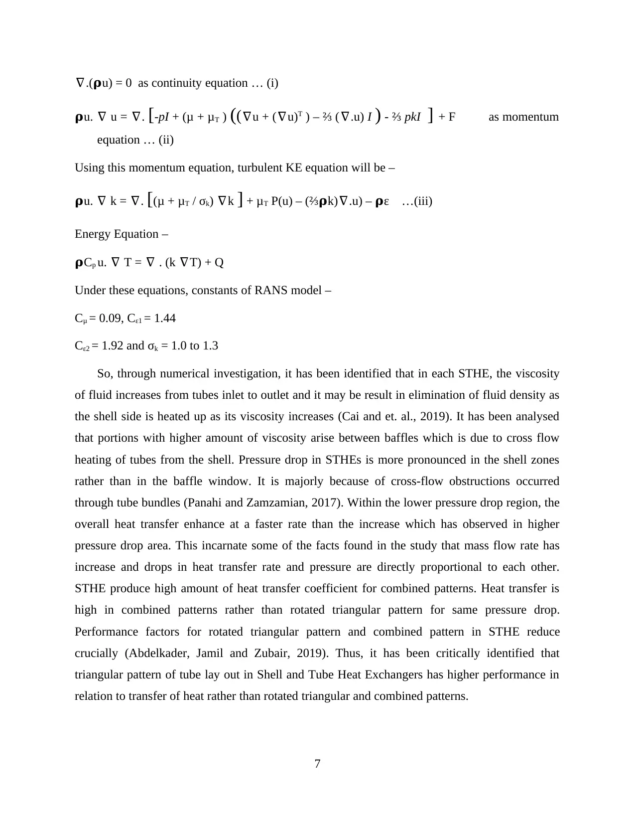
So, through numerical investigation, it has been identified that in each STHE, the viscosity
of fluid increases from tubes inlet to outlet and it may be result in elimination of fluid density as
the shell side is heated up as its viscosity increases (Cai and et. al., 2019). It has been analysed
that portions with higher amount of viscosity arise between baffles which is due to cross flow
heating of tubes from the shell. Pressure drop in STHEs is more pronounced in the shell zones
rather than in the baffle window. It is majorly because of cross-flow obstructions occurred
through tube bundles (Panahi and Zamzamian, 2017). Within the lower pressure drop region, the
overall heat transfer enhance at a faster rate than the increase which has observed in higher
pressure drop area. This incarnate some of the facts found in the study that mass flow rate has
increase and drops in heat transfer rate and pressure are directly proportional to each other.
STHE produce high amount of heat transfer coefficient for combined patterns. Heat transfer is
high in combined patterns rather than rotated triangular pattern for same pressure drop.
Performance factors for rotated triangular pattern and combined pattern in STHE reduce
crucially (Abdelkader, Jamil and Zubair, 2019). Thus, it has been critically identified that
triangular pattern of tube lay out in Shell and Tube Heat Exchangers has higher performance in
relation to transfer of heat rather than rotated triangular and combined patterns.
7
𝛒u. ∇ u = ∇. [-pI + (μ + μT ) ((∇u + (∇u)T ) – ⅔ (∇.u) I ) - ⅔ pkI ] + F as momentum
equation … (ii)
Using this momentum equation, turbulent KE equation will be –
𝛒u. ∇ k = ∇. [(μ + μT / σk) ∇k ] + μT P(u) – (⅔𝛒k)∇.u) – 𝛒ε …(iii)
Energy Equation –
𝛒Cp u. ∇ T = ∇ . (k ∇T) + Q
Under these equations, constants of RANS model –
Cμ = 0.09, Cε1 = 1.44
Cε2 = 1.92 and σk = 1.0 to 1.3
So, through numerical investigation, it has been identified that in each STHE, the viscosity
of fluid increases from tubes inlet to outlet and it may be result in elimination of fluid density as
the shell side is heated up as its viscosity increases (Cai and et. al., 2019). It has been analysed
that portions with higher amount of viscosity arise between baffles which is due to cross flow
heating of tubes from the shell. Pressure drop in STHEs is more pronounced in the shell zones
rather than in the baffle window. It is majorly because of cross-flow obstructions occurred
through tube bundles (Panahi and Zamzamian, 2017). Within the lower pressure drop region, the
overall heat transfer enhance at a faster rate than the increase which has observed in higher
pressure drop area. This incarnate some of the facts found in the study that mass flow rate has
increase and drops in heat transfer rate and pressure are directly proportional to each other.
STHE produce high amount of heat transfer coefficient for combined patterns. Heat transfer is
high in combined patterns rather than rotated triangular pattern for same pressure drop.
Performance factors for rotated triangular pattern and combined pattern in STHE reduce
crucially (Abdelkader, Jamil and Zubair, 2019). Thus, it has been critically identified that
triangular pattern of tube lay out in Shell and Tube Heat Exchangers has higher performance in
relation to transfer of heat rather than rotated triangular and combined patterns.
7
Chapter 3: Research Scope
Significance of research
Enhancement of heat transfer via devices like Shell and Tube Exchangers stills, carried a
high attention of researchers. Therefore, working on this topic and investigating how tube layout
pattern influence the performance of STHE, helps researchers in widening their skills about
concept of transfer (Wang, Zheng, Liu and Liu, 2018). Through investigation, a number of
concepts like whether shell diameter and length of tube also effect heat transfer coefficient or
not, including pressure drop towards shell side with square and triangular pitches can be
analysed. In this regard, to conduct study, the present research will be carried on secondary basis,
where a number of articles will be chosen, under which shell and tube heat exchanger are
designed via utilising a number of equipment, like various parameters for studying the effect of
cutting space, baffle window, shell diameter and tube length, fouling rate on pressure drop and
heat transfer coefficient for shell and tube sides etc. (Saffarian, Fazelpour and Sham, 2019). This
would help in studying the impact of each parameter of such design, which will further lead to
make quick prediction.
8
⊘ This is a preview!⊘
Do you want full access?
Subscribe today to unlock all pages.
Trusted by 1+ million students worldwide
1 out of 20
Related Documents


Your All-in-One AI-Powered Toolkit for Academic Success.
+13062052269
info@desklib.com
Available 24*7 on WhatsApp / Email
![[object Object]](/_next/static/media/star-bottom.7253800d.svg)
Unlock your academic potential
Copyright © 2020–2026 A2Z Services. All Rights Reserved. Developed and managed by ZUCOL.