University Report: ENG-6007B Tuned Circuit and Power Factor Analysis
VerifiedAdded on 2022/08/12
|24
|3077
|13
Report
AI Summary
This technical report details an investigation into tuned circuits and power factor correction. The assignment involves three main parts: estimating the value of an inductor using a designed circuit and frequency variation, designing, building, and testing a tuned filter with a specific resonant frequency and Q factor, and calculating and implementing capacitor-based power factor correction. The report includes circuit diagrams, experimental procedures, results analysis, and discussions on the implications of low industrial power factors and methods for their improvement, such as capacitor banks and synchronous condensers. The work covers the theoretical background, practical implementation, and performance evaluation of these electrical engineering concepts, supported by graphical representations of the experimental data and a discussion on the industrial relevance of power factor correction.

1
Tuned circuit and power factor
Student’s Name
Institutional Affiliation
Date
Tuned circuit and power factor
Student’s Name
Institutional Affiliation
Date
Paraphrase This Document
Need a fresh take? Get an instant paraphrase of this document with our AI Paraphraser
2
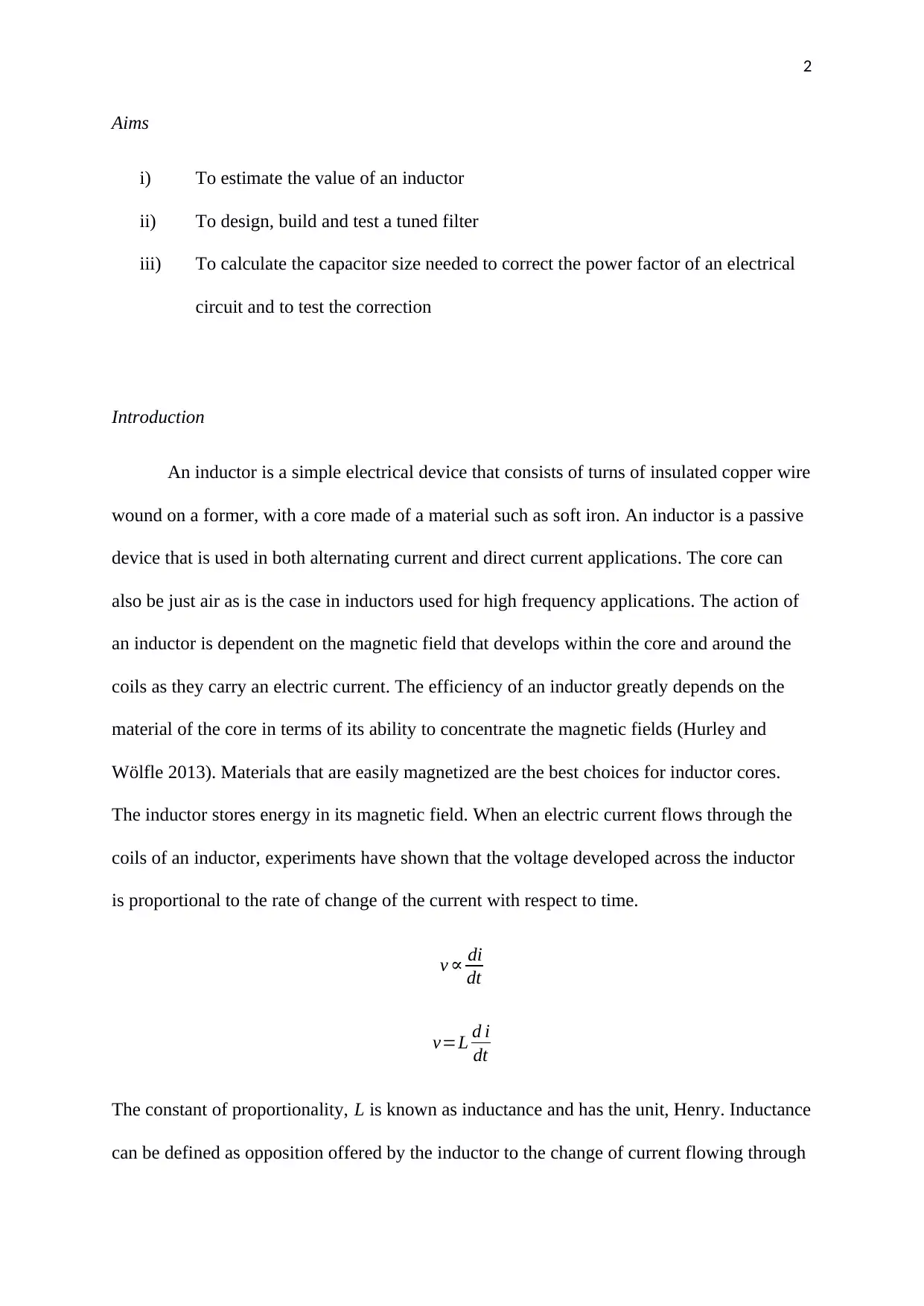
Aims
i) To estimate the value of an inductor
ii) To design, build and test a tuned filter
iii) To calculate the capacitor size needed to correct the power factor of an electrical
circuit and to test the correction
Introduction
An inductor is a simple electrical device that consists of turns of insulated copper wire
wound on a former, with a core made of a material such as soft iron. An inductor is a passive
device that is used in both alternating current and direct current applications. The core can
also be just air as is the case in inductors used for high frequency applications. The action of
an inductor is dependent on the magnetic field that develops within the core and around the
coils as they carry an electric current. The efficiency of an inductor greatly depends on the
material of the core in terms of its ability to concentrate the magnetic fields (Hurley and
Wölfle 2013). Materials that are easily magnetized are the best choices for inductor cores.
The inductor stores energy in its magnetic field. When an electric current flows through the
coils of an inductor, experiments have shown that the voltage developed across the inductor
is proportional to the rate of change of the current with respect to time.
v ∝ di
dt
v=L d i
dt
The constant of proportionality, L is known as inductance and has the unit, Henry. Inductance
can be defined as opposition offered by the inductor to the change of current flowing through
3
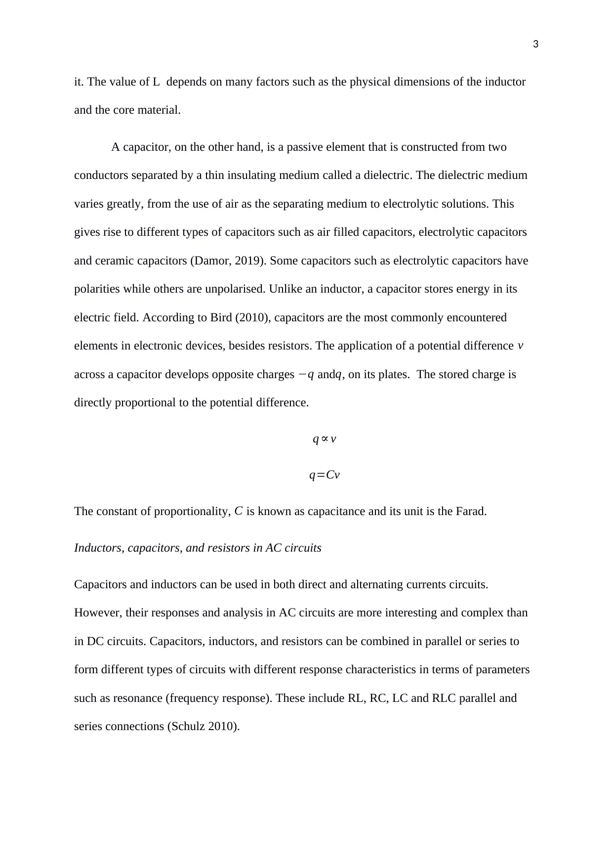
it. The value of L depends on many factors such as the physical dimensions of the inductor
and the core material.
A capacitor, on the other hand, is a passive element that is constructed from two
conductors separated by a thin insulating medium called a dielectric. The dielectric medium
varies greatly, from the use of air as the separating medium to electrolytic solutions. This
gives rise to different types of capacitors such as air filled capacitors, electrolytic capacitors
and ceramic capacitors (Damor, 2019). Some capacitors such as electrolytic capacitors have
polarities while others are unpolarised. Unlike an inductor, a capacitor stores energy in its
electric field. According to Bird (2010), capacitors are the most commonly encountered
elements in electronic devices, besides resistors. The application of a potential difference v
across a capacitor develops opposite charges −q andq, on its plates. The stored charge is
directly proportional to the potential difference.
q ∝ v
q=Cv
The constant of proportionality, C is known as capacitance and its unit is the Farad.
Inductors, capacitors, and resistors in AC circuits
Capacitors and inductors can be used in both direct and alternating currents circuits.
However, their responses and analysis in AC circuits are more interesting and complex than
in DC circuits. Capacitors, inductors, and resistors can be combined in parallel or series to
form different types of circuits with different response characteristics in terms of parameters
such as resonance (frequency response). These include RL, RC, LC and RLC parallel and
series connections (Schulz 2010).
⊘ This is a preview!⊘
Do you want full access?
Subscribe today to unlock all pages.

Trusted by 1+ million students worldwide
4
Power factor and power factor correction
Different electrical loads may require different types of power. Most loads encountered today
such as transformers, motors, and light ballasts are inductive in nature (Batarseh and Wei
2011). According to Clayton (2018), inductive loads demand two types of currents. These
include the real power (working power) needed to carry out the actual task such as motion,
heat generation, and light, and the reactive power which is needed to create and sustain a
magnetic field. Real power is measured in watts while reactive power is measured in VAR
and does not perform any useful work other than circulating between the load and the power
generator. It places a heavier burden on the power supply. Real and reactive power make up
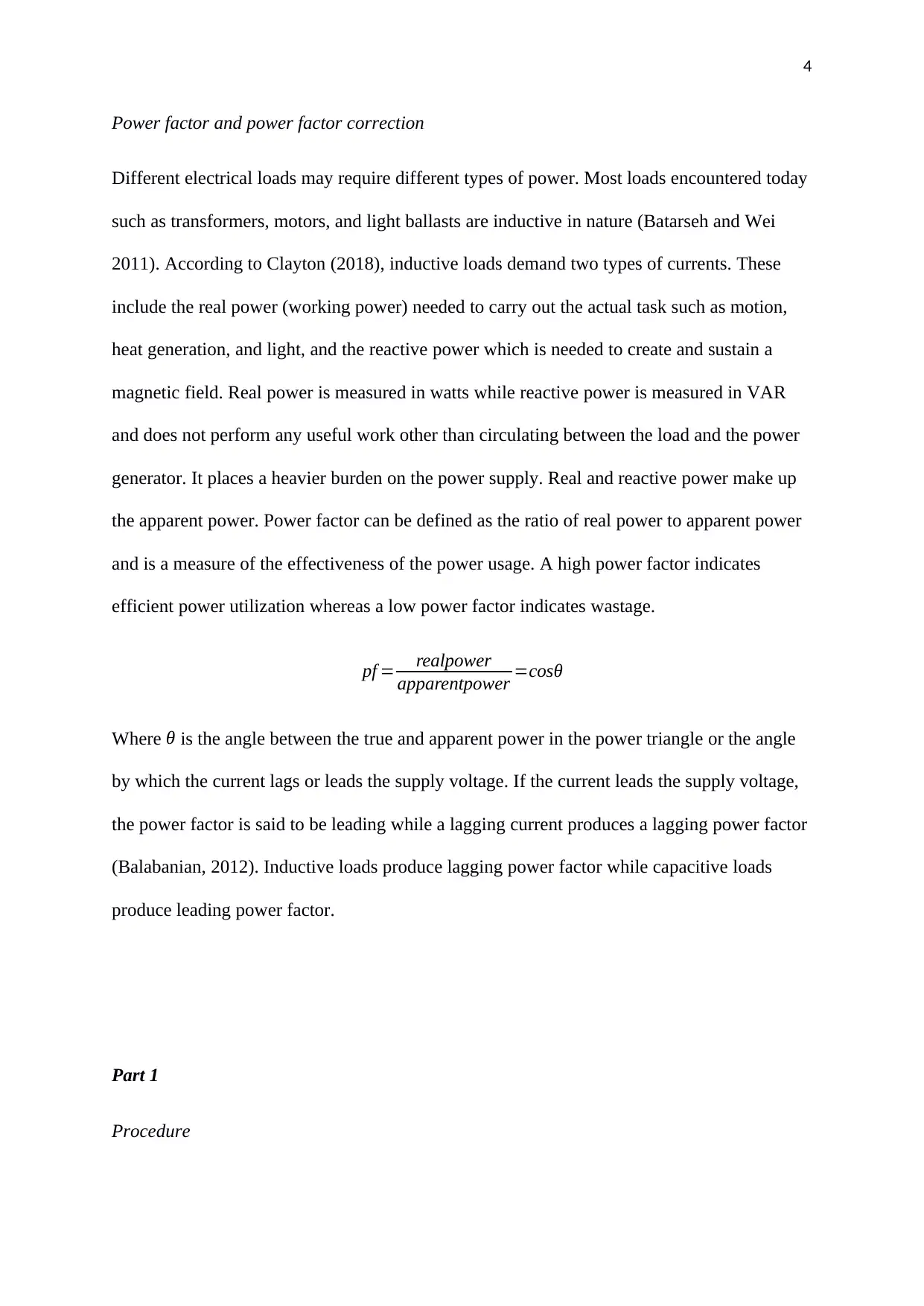
the apparent power. Power factor can be defined as the ratio of real power to apparent power
and is a measure of the effectiveness of the power usage. A high power factor indicates
efficient power utilization whereas a low power factor indicates wastage.
pf = realpower
apparentpower =cosθ
Where θ is the angle between the true and apparent power in the power triangle or the angle
by which the current lags or leads the supply voltage. If the current leads the supply voltage,
the power factor is said to be leading while a lagging current produces a lagging power factor
(Balabanian, 2012). Inductive loads produce lagging power factor while capacitive loads
produce leading power factor.
Part 1
Procedure
Paraphrase This Document
Need a fresh take? Get an instant paraphrase of this document with our AI Paraphraser
5
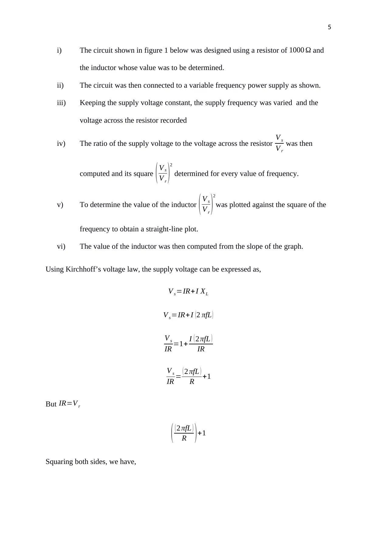
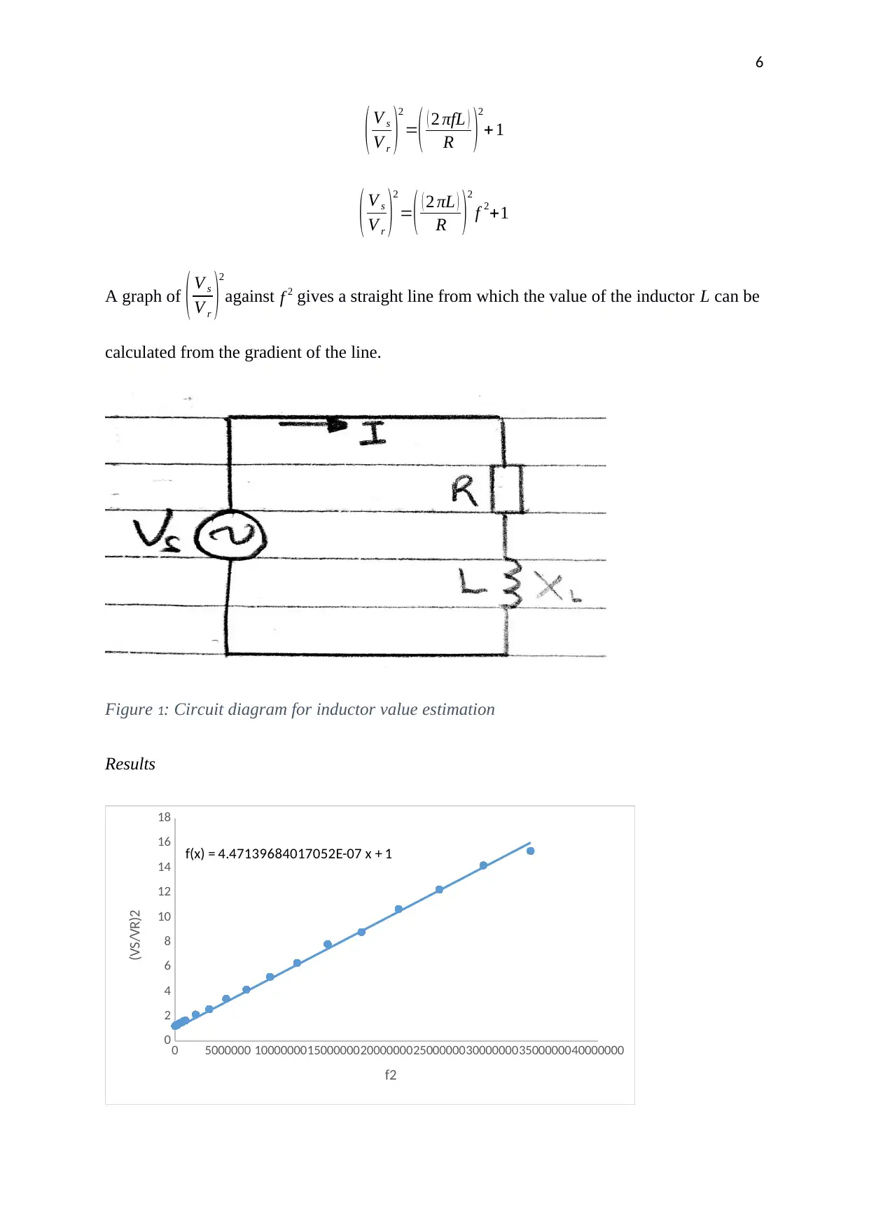
i) The circuit shown in figure 1 below was designed using a resistor of 1000 Ω and
the inductor whose value was to be determined.
ii) The circuit was then connected to a variable frequency power supply as shown.
iii) Keeping the supply voltage constant, the supply frequency was varied and the
voltage across the resistor recorded
iv) The ratio of the supply voltage to the voltage across the resistor V s
V r
was then
computed and its square ( V s
V r )2
determined for every value of frequency.
v) To determine the value of the inductor ( V s
V r )
2
was plotted against the square of the
frequency to obtain a straight-line plot.
vi) The value of the inductor was then computed from the slope of the graph.
Using Kirchhoff’s voltage law, the supply voltage can be expressed as,
V s =IR+I XL
V s =IR+ I ( 2 πfL )
V s
IR =1+ I ( 2 πfL )
IR
V s
IR = ( 2 πfL )
R +1
But IR=V r
( ( 2 πfL )
R )+1
Squaring both sides, we have,
6
( V s
V r )
2
=( ( 2 πfL )
R )
2
+ 1
( V s
V r )
2
=( ( 2 πL )
R )
2
f 2+1
A graph of ( V s
V r )
2
against f 2 gives a straight line from which the value of the inductor L can be
calculated from the gradient of the line.
Figure 1: Circuit diagram for inductor value estimation
Results
0 5000000 10000000150000002000000025000000300000003500000040000000
0
2
4
6
8
10
12
14
16
18
f(x) = 4.47139684017052E-07 x + 1
f2
(VS/VR)2
( V s
V r )
2
=( ( 2 πfL )
R )
2
+ 1
( V s
V r )
2
=( ( 2 πL )
R )
2
f 2+1
A graph of ( V s
V r )
2
against f 2 gives a straight line from which the value of the inductor L can be
calculated from the gradient of the line.
Figure 1: Circuit diagram for inductor value estimation
Results
0 5000000 10000000150000002000000025000000300000003500000040000000
0
2
4
6
8
10
12
14
16
18
f(x) = 4.47139684017052E-07 x + 1
f2
(VS/VR)2
⊘ This is a preview!⊘
Do you want full access?
Subscribe today to unlock all pages.

Trusted by 1+ million students worldwide
7
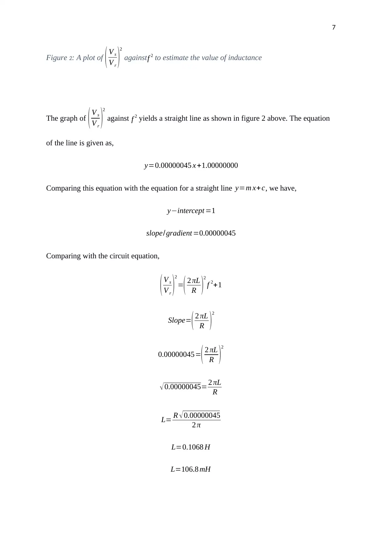
Figure 2: A plot of ( V s
V r )
2
against f 2 to estimate the value of inductance
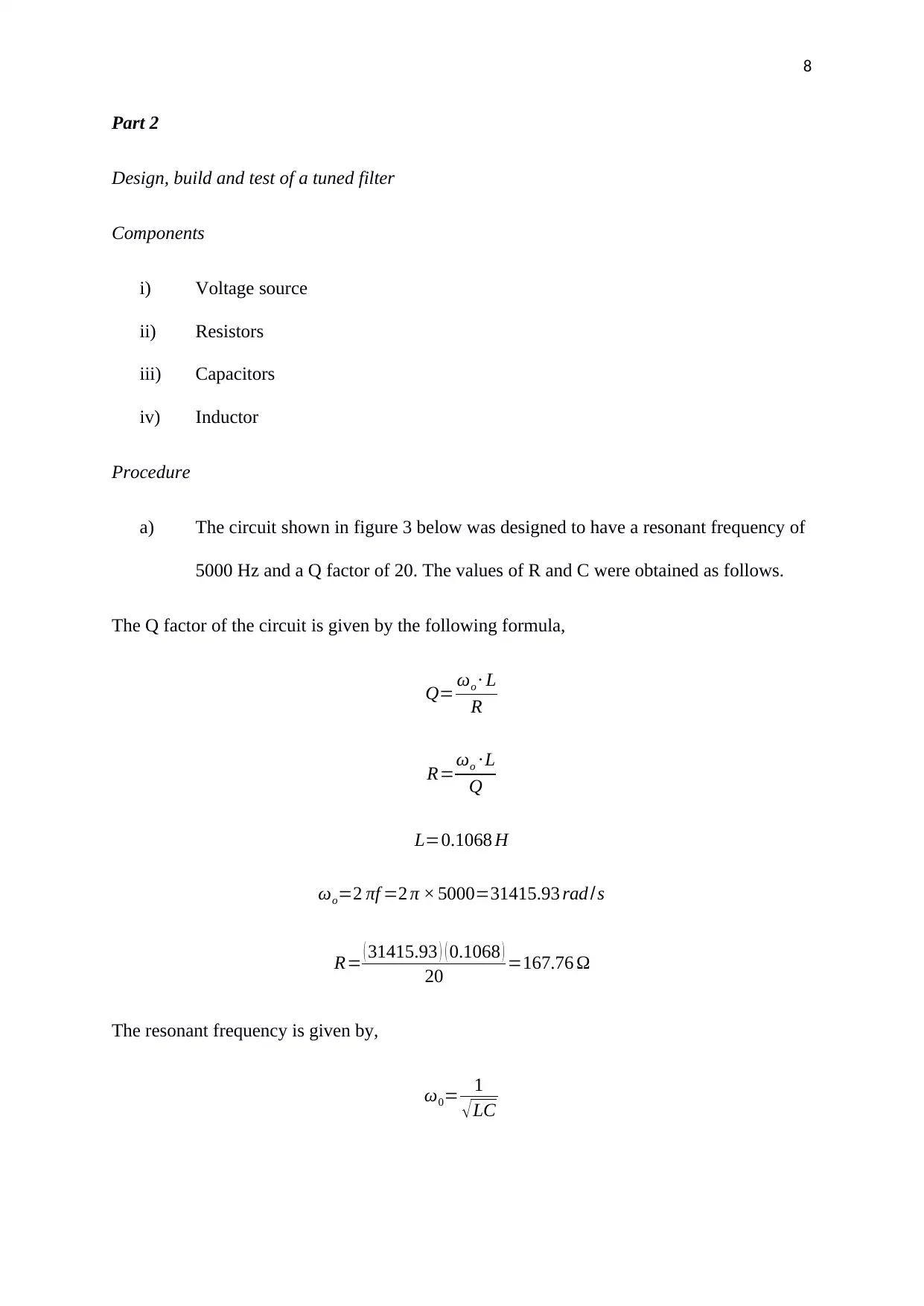
The graph of ( V s
V r )2
against f 2 yields a straight line as shown in figure 2 above. The equation
of the line is given as,
y=0.00000045 x +1.00000000
Comparing this equation with the equation for a straight line y=m x+c, we have,
y−intercept =1
slope/gradient =0.00000045
Comparing with the circuit equation,
( V s
V r )
2
=( 2 πL
R )
2
f 2+1
Slope=( 2 πL
R )
2
0.00000045=( 2 πL
R )
2
√ 0.00000045= 2 πL
R
L= R √0.00000045
2 π
L=0.1068 H
L=106.8 mH
Paraphrase This Document
Need a fresh take? Get an instant paraphrase of this document with our AI Paraphraser
8
Part 2
Design, build and test of a tuned filter
Components
i) Voltage source
ii) Resistors
iii) Capacitors
iv) Inductor
Procedure
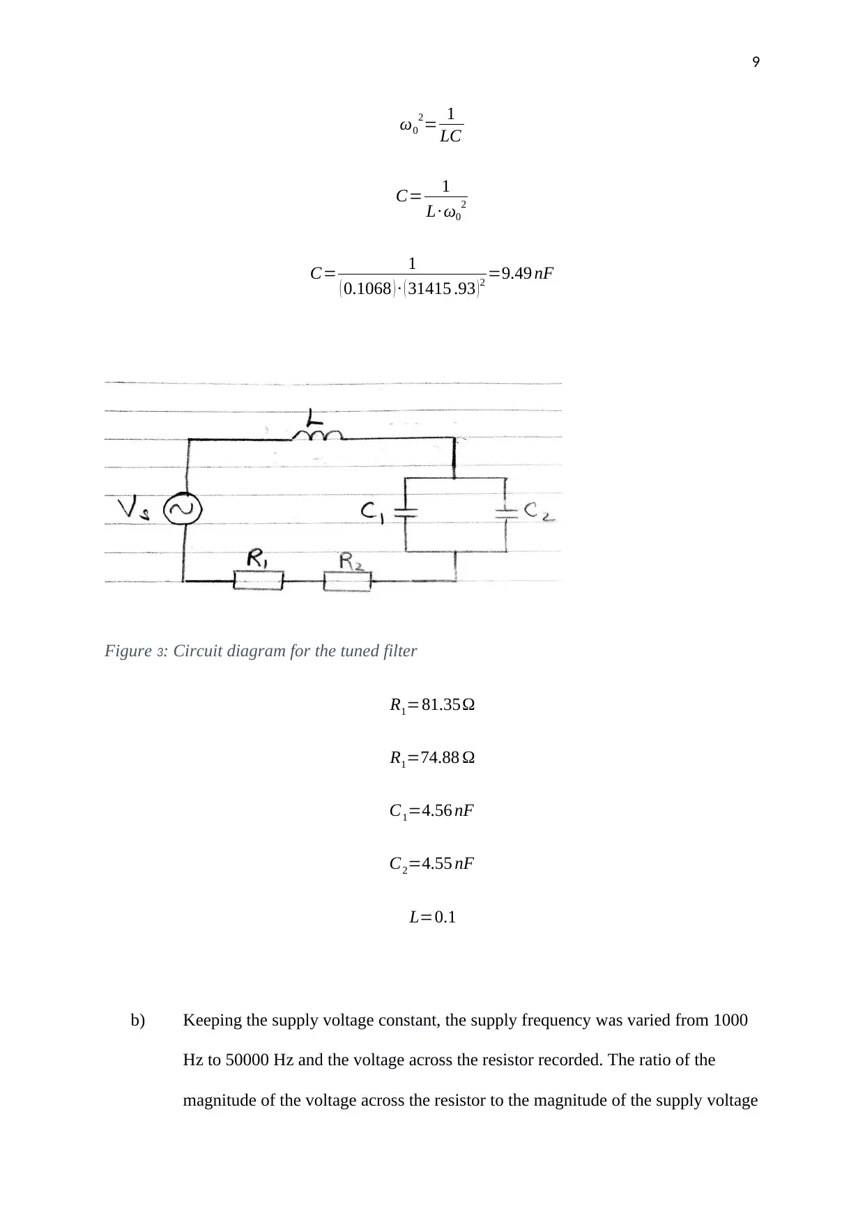
a) The circuit shown in figure 3 below was designed to have a resonant frequency of
5000 Hz and a Q factor of 20. The values of R and C were obtained as follows.
The Q factor of the circuit is given by the following formula,
Q= ωo ∙ L
R
R=ωo ∙ L
Q
L=0.1068 H
ωo=2 πf =2 π × 5000=31415.93 rad /s
R= ( 31415.93 ) ( 0.1068 )
20 =167.76 Ω
The resonant frequency is given by,
ω0= 1
√LC
9
ω0
2= 1
LC
C= 1
L∙ ω0
2
C= 1
( 0.1068 ) ∙ ( 31415 .93 )2 =9.49 nF
Figure 3: Circuit diagram for the tuned filter
R1=81.35Ω
R1=74.88 Ω
C1=4.56 nF
C2=4.55 nF
L=0.1
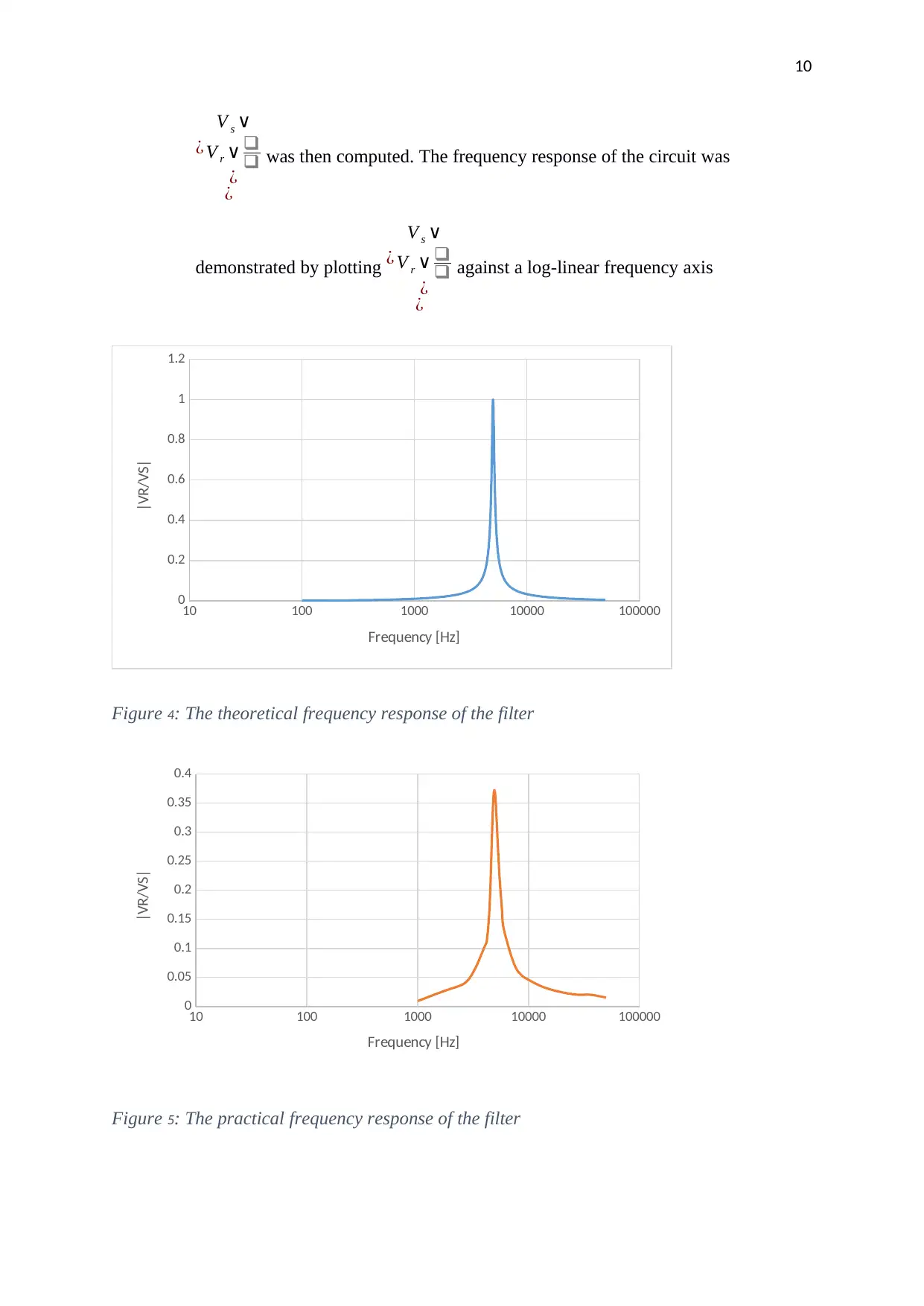
b) Keeping the supply voltage constant, the supply frequency was varied from 1000
Hz to 50000 Hz and the voltage across the resistor recorded. The ratio of the
magnitude of the voltage across the resistor to the magnitude of the supply voltage
⊘ This is a preview!⊘
Do you want full access?
Subscribe today to unlock all pages.

Trusted by 1+ million students worldwide
10
¿
V s ∨
V r ∨ ❑
❑
¿
¿
was then computed. The frequency response of the circuit was
demonstrated by plotting ¿
V s ∨
V r ∨ ❑
❑
¿
¿
against a log-linear frequency axis
10 100 1000 10000 100000
0
0.2
0.4
0.6
0.8
1
1.2
Frequency [Hz]
|VR/VS|
Figure 4: The theoretical frequency response of the filter
10 100 1000 10000 100000
0
0.05
0.1
0.15
0.2
0.25
0.3
0.35
0.4
Frequency [Hz]
|VR/VS|
Figure 5: The practical frequency response of the filter
¿
V s ∨
V r ∨ ❑
❑
¿
¿
was then computed. The frequency response of the circuit was
demonstrated by plotting ¿
V s ∨
V r ∨ ❑
❑
¿
¿
against a log-linear frequency axis
10 100 1000 10000 100000
0
0.2
0.4
0.6
0.8
1
1.2
Frequency [Hz]
|VR/VS|
Figure 4: The theoretical frequency response of the filter
10 100 1000 10000 100000
0
0.05
0.1
0.15
0.2
0.25
0.3
0.35
0.4
Frequency [Hz]
|VR/VS|
Figure 5: The practical frequency response of the filter
Paraphrase This Document
Need a fresh take? Get an instant paraphrase of this document with our AI Paraphraser
11
c)
i) Below the resonance frequency, the voltage across the resistor lags behind the supply
voltage due to the inductive nature of the circuit.
ii) At the resonance frequency, the circuit is purely resistive. The voltage across the resistor
will be in phase with the supply voltage
iii) Above the resonance frequency, the phase shift increases in the opposite direction and the
two voltages will be almost 180 degrees out of phase.
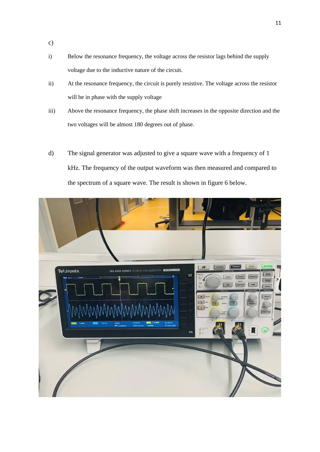
d) The signal generator was adjusted to give a square wave with a frequency of 1
kHz. The frequency of the output waveform was then measured and compared to
the spectrum of a square wave. The result is shown in figure 6 below.
12
Figure 6: Input and output waveforms from the filter fed with a square wave
e)
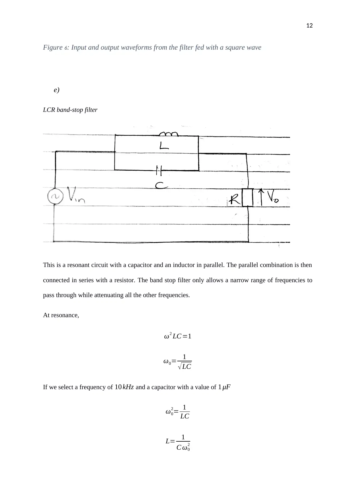
LCR band-stop filter
This is a resonant circuit with a capacitor and an inductor in parallel. The parallel combination is then
connected in series with a resistor. The band stop filter only allows a narrow range of frequencies to
pass through while attenuating all the other frequencies.
At resonance,
ω2 LC =1
ω0= 1
√LC
If we select a frequency of 10 kHz and a capacitor with a value of 1 μF
ω0
2= 1
LC
L= 1
C ω0
2
⊘ This is a preview!⊘
Do you want full access?
Subscribe today to unlock all pages.

Trusted by 1+ million students worldwide
1 out of 24
Related Documents
Your All-in-One AI-Powered Toolkit for Academic Success.
+13062052269
info@desklib.com
Available 24*7 on WhatsApp / Email
![[object Object]](/_next/static/media/star-bottom.7253800d.svg)
Unlock your academic potential
Copyright © 2020–2026 A2Z Services. All Rights Reserved. Developed and managed by ZUCOL.


