University Assignment: Analysis of Turbine Test and Design (ME7725)
VerifiedAdded on 2022/09/07
|17
|2487
|16
Homework Assignment
AI Summary
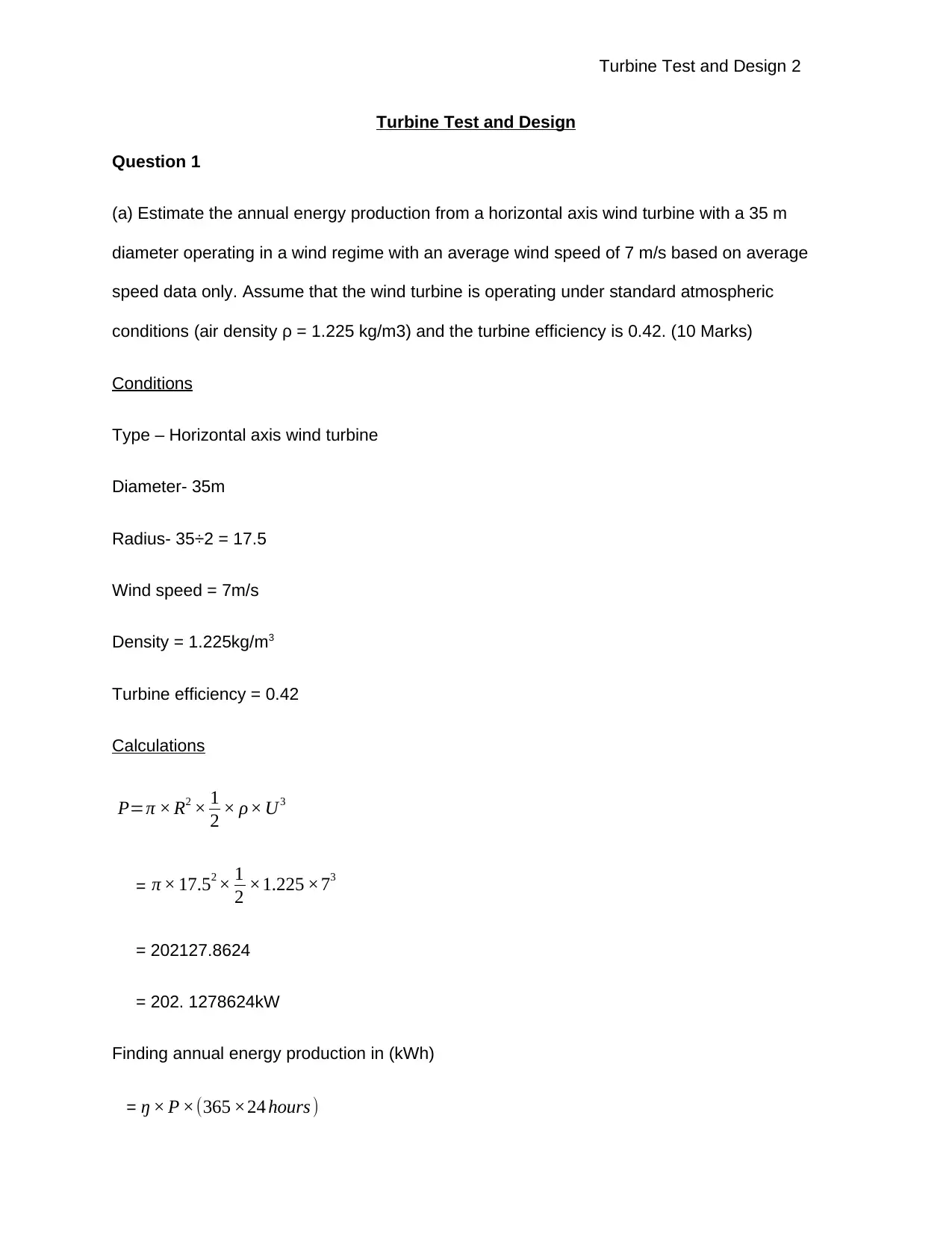
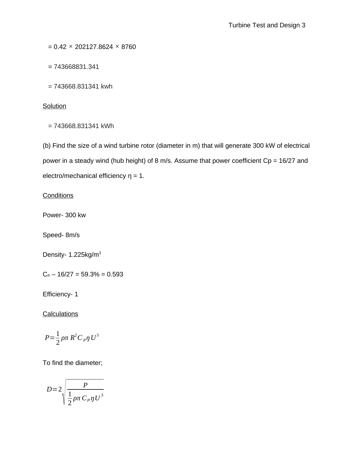
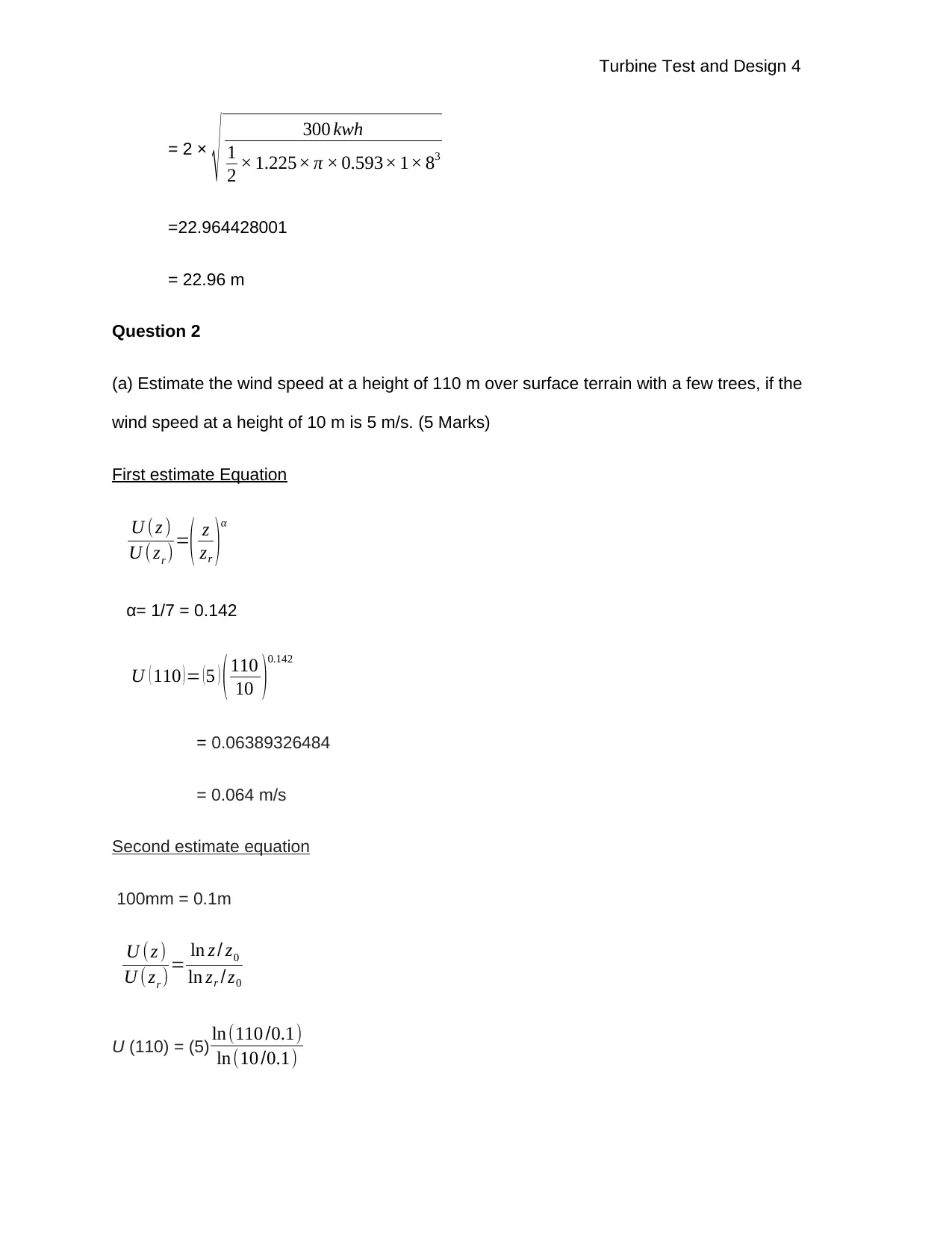
This assignment focuses on the design and analysis of wind turbines. It begins with calculations of annual energy production, rotor diameter, and wind speed estimation. The solution explores the factors influencing material selection for blade construction, discussing wood composite and glass fiber reinforced plastic. The capacity factor is defined, and a comparison between nuclear and wind power plants is provided. Further calculations determine rotational speed, tip speed, and gear ratio for a three-bladed wind turbine. The assignment then delves into blade design using Betz and Schmitz methods, including chord length and twist angle calculations. Finally, it analyzes the lift and drag characteristics of a NACA 4415 aerofoil, determining the best operating point and stall conditions, and assessing the maximum power output of a wind turbine based on a wind speed histogram.

Turbine Test and Design 1
Turbine Test and Design
By
Professor
University
Course
City
Date of submission
Turbine Test and Design
By
Professor
University
Course
City
Date of submission
Paraphrase This Document
Need a fresh take? Get an instant paraphrase of this document with our AI Paraphraser

Turbine Test and Design 2
Turbine Test and Design
Question 1
(a) Estimate the annual energy production from a horizontal axis wind turbine with a 35 m
diameter operating in a wind regime with an average wind speed of 7 m/s based on average
speed data only. Assume that the wind turbine is operating under standard atmospheric
conditions (air density ρ = 1.225 kg/m3) and the turbine efficiency is 0.42. (10 Marks)
Conditions
Type – Horizontal axis wind turbine
Diameter- 35m
Radius- 35÷2 = 17.5
Wind speed = 7m/s
Density = 1.225kg/m3
Turbine efficiency = 0.42
Calculations
P=π × R2 × 1
2 × ρ× U3
= π × 17.52 × 1
2 ×1.225 ×73
= 202127.8624
= 202. 1278624kW
Finding annual energy production in (kWh)
= ŋ × P ×(365 ×24 hours )

Turbine Test and Design 3
= 0.42 × 202127.8624 × 8760
= 743668831.341
= 743668.831341 kwh
Solution
= 743668.831341 kWh
(b) Find the size of a wind turbine rotor (diameter in m) that will generate 300 kW of electrical
power in a steady wind (hub height) of 8 m/s. Assume that power coefficient Cp = 16/27 and
electro/mechanical efficiency η = 1.
Conditions
Power- 300 kw
Speed- 8m/s
Density- 1.225kg/m3
CP – 16/27 = 59.3% = 0.593
Efficiency- 1
Calculations
P= 1
2 ρπ R2 C P ŋ U3
To find the diameter;
D=2
√ P
1
2 ρπ CP ŋU 3
⊘ This is a preview!⊘
Do you want full access?
Subscribe today to unlock all pages.

Trusted by 1+ million students worldwide

Turbine Test and Design 4
= 2 ×
√ 300 kwh
1
2 × 1.225× π × 0.593× 1× 83
=22.964428001
= 22.96 m
Question 2
(a) Estimate the wind speed at a height of 110 m over surface terrain with a few trees, if the
wind speed at a height of 10 m is 5 m/s. (5 Marks)
First estimate Equation
U (z )
U ( zr )=
( z
zr )
α
α= 1/7 = 0.142
U ( 110 ) = ( 5 ) ( 110
10 )
0.142
= 0.06389326484
= 0.064 m/s
Second estimate equation
100mm = 0.1m
U ( z )
U ( zr )= ln z / z0
ln zr / z0
U (110) = (5) ln(110 /0.1)
ln(10 /0.1)
Paraphrase This Document
Need a fresh take? Get an instant paraphrase of this document with our AI Paraphraser

Turbine Test and Design 5
= 0.06912256102
= 0.069 m/s
(b) Wind turbine blades are made in many different ways and from many different materials.
Discuss the most important factors in the selection of materials for blade construction and
describe how wood composite and glass fiber reinforced plastic is used to make blades.
Solution
Composite materials are best suited to blade designs since they have an accelerate spin and
the winds attack the blades at a very low velocity. Combining materials helps make the blades
lighter and easier for construction (Chong et al., 2017, 92). These materials have varying
physical and chemical properties hence making the final product stronger and long-lasting. That
is why glass fiber incorporated with resin and wood is used in blade construction. The
composites are less corrosive and they incur low costs. The materials meet the majority of
mechanical properties hence they offer high performance (Mishnaevsky, 2014, 1285).
Question 3
(a) The capacity factor is a useful parameter when comparing the performance of energy
sources. What is the definition of the capacity factor?
The capacity factor is the ratio of average power produced to the actual power output over a
given period. It is calculated as the average power divided by peak power. The capacity factor
varies with the design of the plant and fuel used in operation. The capacity factor is the average
power produced, divided by the rated peak power (Zhao et al., 2019, 641).
(b) A typical nuclear power plant has a capacity factor of around 90%, while the capacity factor
for large scale wind turbines is around 40% (see Figure Q3). Discuss the reason for such a
wide gap between the capacity factors of these two types of energy production systems

Turbine Test and Design 6
solution
Capacity factors differ greatly depending on the design of the plant and the type of fuel it uses.
Therefore, a wide gap between the capacity factors of the nuclear power plant and a wind
turbine. The capacity factors vary depending on the amount of power produces. A nuclear
power plant consumes and produces high powers hence a higher capacity factor while a wind
turbine consumes less energy and power hence a lower capacity factor (Keech, 2017, 728).
Question 4
A three-bladed wind turbine with a radius of 50 m produces 1500 kW at a wind speed of 11 m/s.
Air density is 1.225 kg/m3. Under these conditions
(i) What is the rotational speed of the rotor in rpm when it operates at a tip speed ratio
of TSR=6?
Conditions
Type- three-bladed wind turbine
Radius- 50m
Power- 1500Kw
Speed- 11m/s
Density- 1.225 kg/m3
Tip Speed Ratio- 6
Calculations
Tip speed ratio tsr= Ω × R
U
⊘ This is a preview!⊘
Do you want full access?
Subscribe today to unlock all pages.

Trusted by 1+ million students worldwide

Turbine Test and Design 7
Ω = TSR× U
R
= 6 ×11
50
= 1.32 rad/s
Nrotor = Ω ×60 s /minute
2× π rads / revolution
= 124.40706908 rpm ≈ 124.41 rpm
(ii) What is the tip speed of the rotor?
The tip speed of the rotor Utip = Ω × R
Since Ω was 1.32 rad/s from the equation in roman one
Therefore, tip speed rotor = 1.32 × 50
= 66 m/s
(iii) If the generator needs to turn at 1800 rpm, what gear ratio of the generator to the
rotor is needed to match the rotor speed to the generator speed?
Ngenerator = 1800 rpm
Nrotor = 124.41 rpm
Gear box ratio = N generator
Nrotor
= 1800 rpm
124.41rpm
= 14.468290330 ≈ 14.47
(iv) What is the overall efficiency of the complete wind turbine (blades, gearbox, and
generator) under these conditions?
Paraphrase This Document
Need a fresh take? Get an instant paraphrase of this document with our AI Paraphraser

Turbine Test and Design 8
P= 1
2 ρπ R2 C p ŋ U3
Assume Betz limit is 16/27 ≈ 0.593%
Therefore, to find efficiency;
ŋ= P
1
2 ρπ R2 CP U3
=
1500× 103
1
2 × 1.225× π × 502 × 0.593× 113
= 0.39505952371
= 0.40
Question 5
Design an optimum blade based on Betz and Schmitz for a three-bladed turbine. The lift-to-drag
ratio and the lift coefficient of the aerofoil against the angle of attack (AoA) are given
in Figure Q5.1, and the exact values from these curves are tabulated in Table Q5.1. The
curves giving the power coefficient against the tip speed ratio (TSR) for typical three-bladed
machines can be found in Figure Q5.2.

Turbine Test and Design 9
⊘ This is a preview!⊘
Do you want full access?
Subscribe today to unlock all pages.

Trusted by 1+ million students worldwide

Turbine Test and Design 10
(a) Give formulas for calculating the chord length and the pitch angle of the blade based on
optimum Betz and Schmitz methods. Note that the pitch angle is defined as the angle
between the chord line and the plane of blade rotation. Assume a pitch angle of zero.
Explain all symbols and quantities that appear in the formulas and draw a figure
explaining the angles.
Paraphrase This Document
Need a fresh take? Get an instant paraphrase of this document with our AI Paraphraser

Turbine Test and Design 11
Solution
The air hits an airfoil blade at an angle known as the angle of attack, the symbol is αA. The line
on the blade that gives the reference point is the chord line. The forces acting on the blade are
divided into two, the drag force (FD) and the lift force which acts perpendicular to the direction of
the wind (Appa et al., 2017, 371).
The angle of attack diagram
Lift force = CL
1
2 ρ w2( bc), that is; coefficient of lift (CL), density, wind speed (w), blade width (b)
and length of chord line (c) multiplied together.
Drag force = CD 1
2 ρW 2(bc)
Where CD is the coefficient of drag and others are similar to those in lift force formulae.
The coefficient of drag and coefficient of lift relies directly on the angle of attack. When the
angles of attack exceed 15 degrees, a stall is experienced since air is not attached to the blades
anymore. Glide ratio is the ratio of the coefficient of lift to the coefficient of drag (Shain et al.,
2018, 508).
GR= CL/CD

Turbine Test and Design 12
Diagrammatic representations of angles.
β(r) is the pitch angle, γ(r) is the angle between the rotor axis and wind while φ(r) is the angle
between the rotor plane and wind direction. R is the radius where c is chord.
According to Betz, finding the pitch angle does not entail the wind rotation. Therefore, a=0.
W2 = v2 + u2 whereas u= wr since a is zero. ω is equal to the product of, two, pi and efficiency
(2πn). Tp speed ratio (X) is equal to V tip
V = ωR
v
All the equations joined gives γ(r) = 3rx/ 2R while φ (r) is equal t 2R/ 3Rx.
Therefore, Pitch angle β(r) = arctan 2 R
3 rX −αD . Where αD is the angle of attack which is always
the angle that offers the highest glide on the blade.
According to betz, the chord length c(r) =
16 πR
9 B CL , D
1
X
√ X2 ( r
R )2
+ 4
9
where CL,D is the coefficient of lift
at the angle of attack.
Formula by Schmitz states the pitch angle β(r) = 2
3 arctan R
rX −α D whereas the chord length
⊘ This is a preview!⊘
Do you want full access?
Subscribe today to unlock all pages.

Trusted by 1+ million students worldwide
1 out of 17

Your All-in-One AI-Powered Toolkit for Academic Success.
+13062052269
info@desklib.com
Available 24*7 on WhatsApp / Email
Unlock your academic potential
Copyright © 2020–2025 A2Z Services. All Rights Reserved. Developed and managed by ZUCOL.