Construction Technology 4: Tyremax Building Steel Construction Report
VerifiedAdded on 2022/10/01
|28
|7843
|13
Report
AI Summary
This report provides a comprehensive analysis of the Tyremax low-rise warehouse building, focusing on its steel construction. The report details the structural system, including portal frames, and typical members such as corner columns, endwall grits, and frame columns. It examines the loads acting on the structure, calculation of member strengths, and constructibility aspects, including the use of computer-aided design tools. The analysis includes site visits, photographs, and 3D renderings. The report also discusses various composite structures used in the Australian construction industry, such as steel-concrete, timber-concrete, and reinforced fiber composites. The assignment covers structural member-to-member connection details and wind loading calculations. The project followed a structured project plan, with clearly defined roles for each group member. The report concludes with an analysis of the building's structural frame and a discussion of the forces it must withstand.
Construction Technology Group Assignment- Tyremax Building
Paraphrase This Document
Need a fresh take? Get an instant paraphrase of this document with our AI Paraphraser
Contents
Introduction......................................................................................................................................................3
Progress Report................................................................................................................................................3
Structural System and typical membership.....................................................................................................11
Loads..............................................................................................................................................................12
Calculations of strength..................................................................................................................................12
Constructibility aspects...................................................................................................................................13
Project Plan....................................................................................................................................................13
Report.............................................................................................................................................................15
The Analysis of the Building..........................................................................................................................15
Height and Clear Span....................................................................................................................................18
The Main Frame.............................................................................................................................................19
Restraint Positions..........................................................................................................................................19
Common composite structures utilized in the Australian construction industry.............................................20
Introduction....................................................................................................................................................20
Discussion......................................................................................................................................................20
Steel-Concrete Composite (SCC)...................................................................................................................21
Composite Slabs.............................................................................................................................................23
Composite Beams Flexural Strength..............................................................................................................24
Composite Beams...........................................................................................................................................25
Composite Columns and Frames....................................................................................................................25
Timber-Concrete-Composite (TCC)...............................................................................................................26
Reinforced Fiber Composites (RFPs).............................................................................................................27
Reinforced Polymer Composites (RPCs)........................................................................................................28
References......................................................................................................................................................29
Group Members and Student Numbers
Group member name Student Number Signature
Introduction
Steel is a versatile material that is widely used in the building and construction sector, as well as
other industries. Steel structures are constructed using steel as the main raw material and these
buildings excel in terms of ease of construction, long life span, low costs, and energy savings. Metal
structures have high durability and the versatility of steel makes it a premium and first choice
material in construction. In this paper, the Tyremax low rise warehouse building is the focus of the
study; the building is located on Baile Road, in Canningvale, Perth. This project entails an
evaluation of the Tyremax building, a low rise warehouse building with two floors/ storeys to house
offices, and largely a single free standing warehouse. The evaluation involves a discussion of the
structural system typical members and their roles, the loads on the structure, and a computation of
common buildings’ members strengths of some of the buildings’ common members. The paper also
discusses the connection details of structural members along with the constructibility aspects of the
building using steel. The assignment involves making a visit to the building site with some photos
taken (see Illustrations 1 to 10) and design images as well.
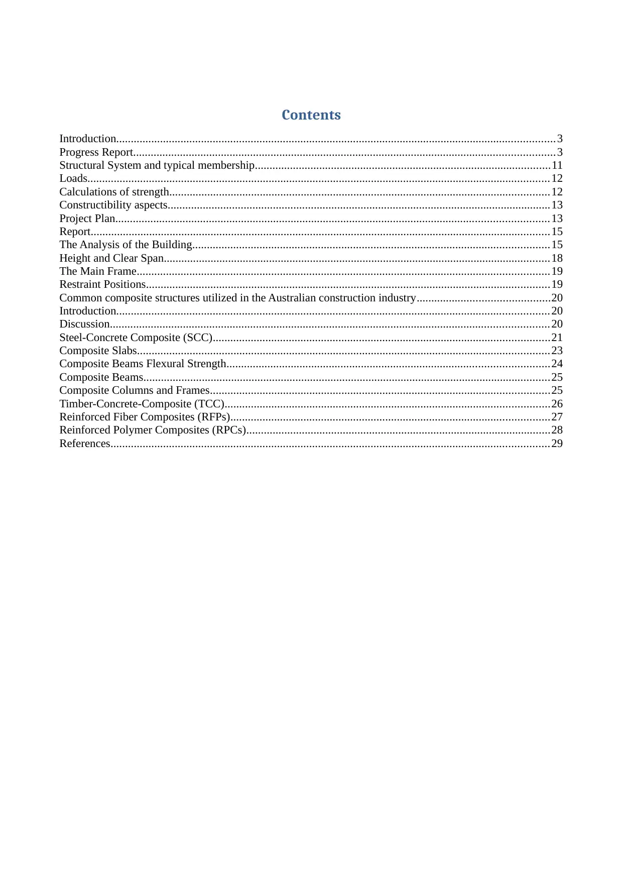
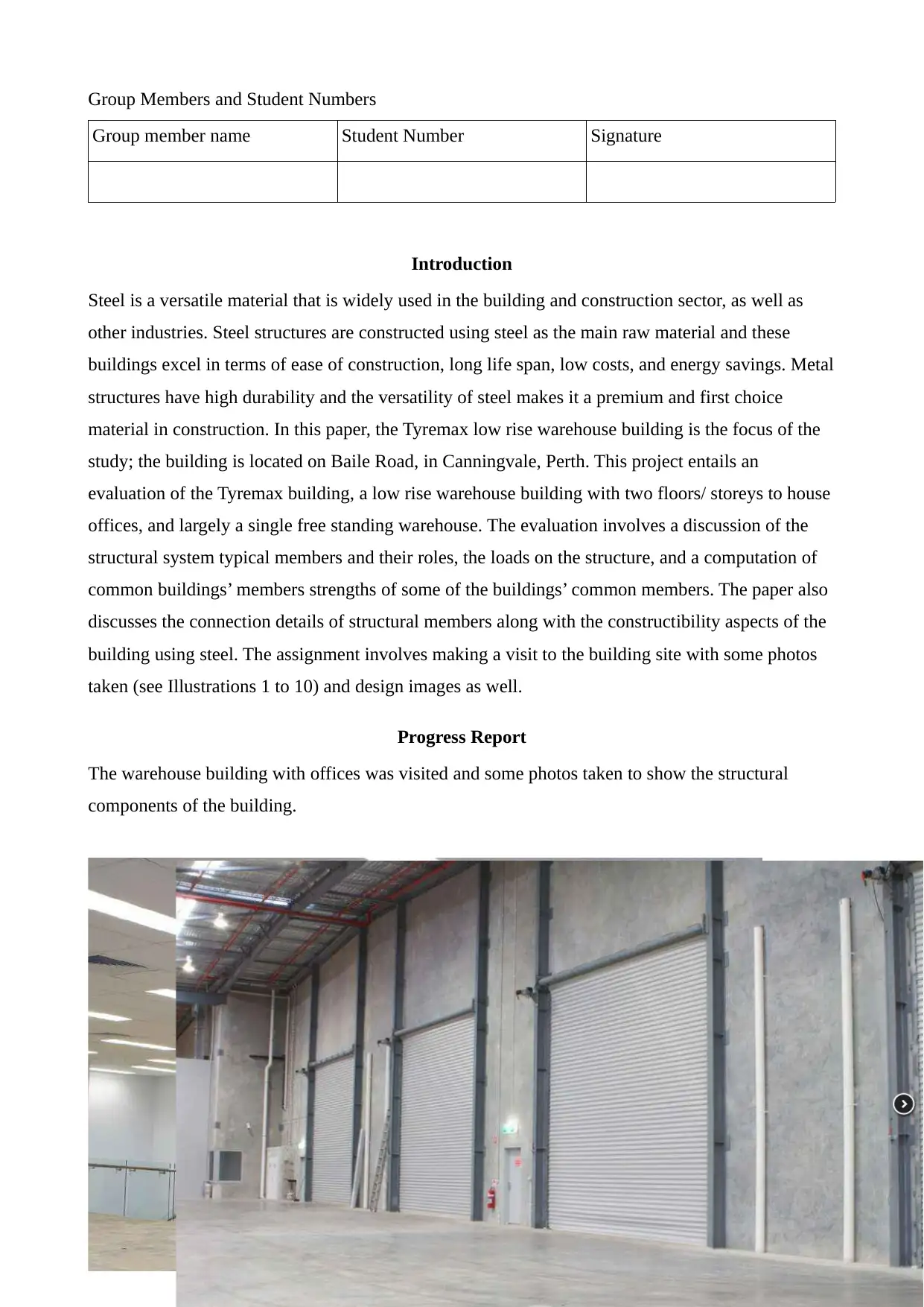
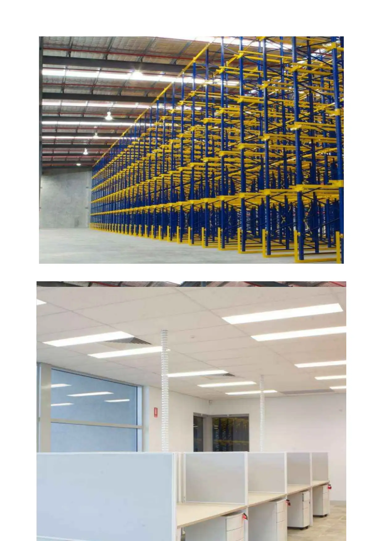
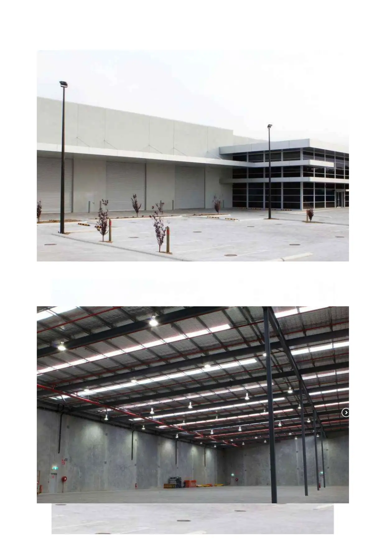
Progress Report
The warehouse building with offices was visited and some photos taken to show the structural
components of the building.
Group member name Student Number Signature
Introduction
Steel is a versatile material that is widely used in the building and construction sector, as well as
other industries. Steel structures are constructed using steel as the main raw material and these
buildings excel in terms of ease of construction, long life span, low costs, and energy savings. Metal
structures have high durability and the versatility of steel makes it a premium and first choice
material in construction. In this paper, the Tyremax low rise warehouse building is the focus of the
study; the building is located on Baile Road, in Canningvale, Perth. This project entails an
evaluation of the Tyremax building, a low rise warehouse building with two floors/ storeys to house
offices, and largely a single free standing warehouse. The evaluation involves a discussion of the
structural system typical members and their roles, the loads on the structure, and a computation of
common buildings’ members strengths of some of the buildings’ common members. The paper also
discusses the connection details of structural members along with the constructibility aspects of the
building using steel. The assignment involves making a visit to the building site with some photos
taken (see Illustrations 1 to 10) and design images as well.
Progress Report
The warehouse building with offices was visited and some photos taken to show the structural
components of the building.
⊘ This is a preview!⊘
Do you want full access?
Subscribe today to unlock all pages.
Trusted by 1+ million students worldwide
Paraphrase This Document
Need a fresh take? Get an instant paraphrase of this document with our AI Paraphraser
⊘ This is a preview!⊘
Do you want full access?
Subscribe today to unlock all pages.
Trusted by 1+ million students worldwide
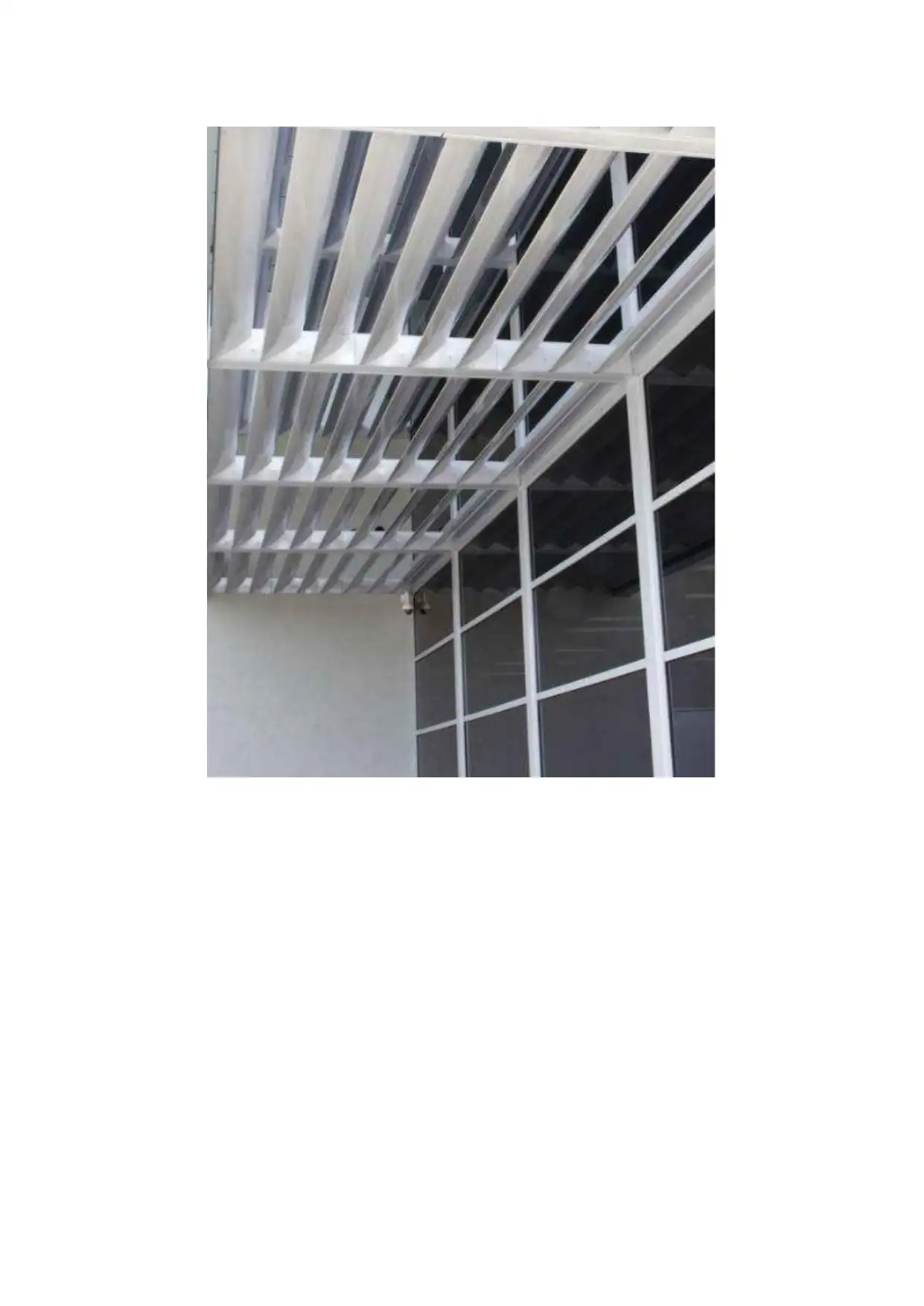
Structural System and typical membership
Steel is used as the main construction and support material; the entire Eave height of the building is
made of structural steel that provides the main support for the building. At the end of the corners is
the Corner column, made of structural steel and along the length of the sides of the building (width)
is the Endwall Grit, also made of steel. Towards the rooftop is a Endwall Rafter and along the width
of the building are Endwall Columns, also made of steel. The front and back of the building have a
Paraphrase This Document
Need a fresh take? Get an instant paraphrase of this document with our AI Paraphraser
Sidewall Grit steel material and along the entire length are Frame Columns (spaced out). Rod
bracings are used along the length to provide extra support; they join with the frame column and are
diagonally placed. The entrance has a steel framed opening jamb while at its top (horizontally
placed) is the framed opening header. Along the length of the building are supporting columns and
from the centerline of one steel column to the next is a sidewall bay. On the roof are Eave Struts
running along the length of the warehouse building. Running along the width of the building are
Frame rafters that also provide support for roof members and gives the building rigidity while also
supporting the purlins and roof members’ weight. These work to produce a rigid steel frame
building
The skeleton structure of the building is made of various steel structures and component members
that ensure strength and rigidity for the entire building. Trusses made up of strong steel members
connected using hinged connections at their end for the main roof members. These are made of light
steel members that give strength and rigidity and support the roof weight while also providing a
framework for the buildings’ top covering.
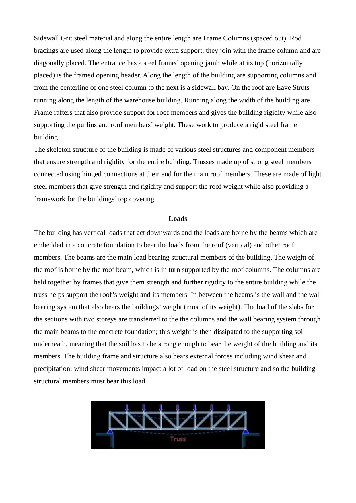
Loads
The building has vertical loads that act downwards and the loads are borne by the beams which are
embedded in a concrete foundation to bear the loads from the roof (vertical) and other roof
members. The beams are the main load bearing structural members of the building. The weight of
the roof is borne by the roof beam, which is in turn supported by the roof columns. The columns are
held together by frames that give them strength and further rigidity to the entire building while the
truss helps support the roof’s weight and its members. In between the beams is the wall and the wall
bearing system that also bears the buildings’ weight (most of its weight). The load of the slabs for
the sections with two storeys are transferred to the the columns and the wall bearing system through
the main beams to the concrete foundation; this weight is then dissipated to the supporting soil
underneath, meaning that the soil has to be strong enough to bear the weight of the building and its
members. The building frame and structure also bears external forces including wind shear and
precipitation; wind shear movements impact a lot of load on the steel structure and so the building
structural members must bear this load.
bracings are used along the length to provide extra support; they join with the frame column and are
diagonally placed. The entrance has a steel framed opening jamb while at its top (horizontally
placed) is the framed opening header. Along the length of the building are supporting columns and
from the centerline of one steel column to the next is a sidewall bay. On the roof are Eave Struts
running along the length of the warehouse building. Running along the width of the building are
Frame rafters that also provide support for roof members and gives the building rigidity while also
supporting the purlins and roof members’ weight. These work to produce a rigid steel frame
building
The skeleton structure of the building is made of various steel structures and component members
that ensure strength and rigidity for the entire building. Trusses made up of strong steel members
connected using hinged connections at their end for the main roof members. These are made of light
steel members that give strength and rigidity and support the roof weight while also providing a
framework for the buildings’ top covering.
Loads
The building has vertical loads that act downwards and the loads are borne by the beams which are
embedded in a concrete foundation to bear the loads from the roof (vertical) and other roof
members. The beams are the main load bearing structural members of the building. The weight of
the roof is borne by the roof beam, which is in turn supported by the roof columns. The columns are
held together by frames that give them strength and further rigidity to the entire building while the
truss helps support the roof’s weight and its members. In between the beams is the wall and the wall
bearing system that also bears the buildings’ weight (most of its weight). The load of the slabs for
the sections with two storeys are transferred to the the columns and the wall bearing system through
the main beams to the concrete foundation; this weight is then dissipated to the supporting soil
underneath, meaning that the soil has to be strong enough to bear the weight of the building and its
members. The building frame and structure also bears external forces including wind shear and
precipitation; wind shear movements impact a lot of load on the steel structure and so the building
structural members must bear this load.
Calculations of strength
The building must be built to withstand wind shear forces and this requires computing the basic
wind velocity, mean wind velocity, turbulence, and turbulence intensity as well as peak velocity
pressure in order to determine the strengths of component members to be used.
Structural member to member connection details
The building components and structural members are designed using portal frames to assemble
together the columns, beams, and other structural members. These are used because they confer
minimal obstruction to architectural elements and layout of the building. The building is a low rose
one and so rigid frames become the best alternative because they ensure the highest efficiency and
to ensure maximum frame action is attained. There are fully welded connections that have stiff ends
are used extensively, especially on the roof and rafter members. Knee connection with the end
plates welded are also used for connecting members as are welded T- connections and bolted T-
connections.
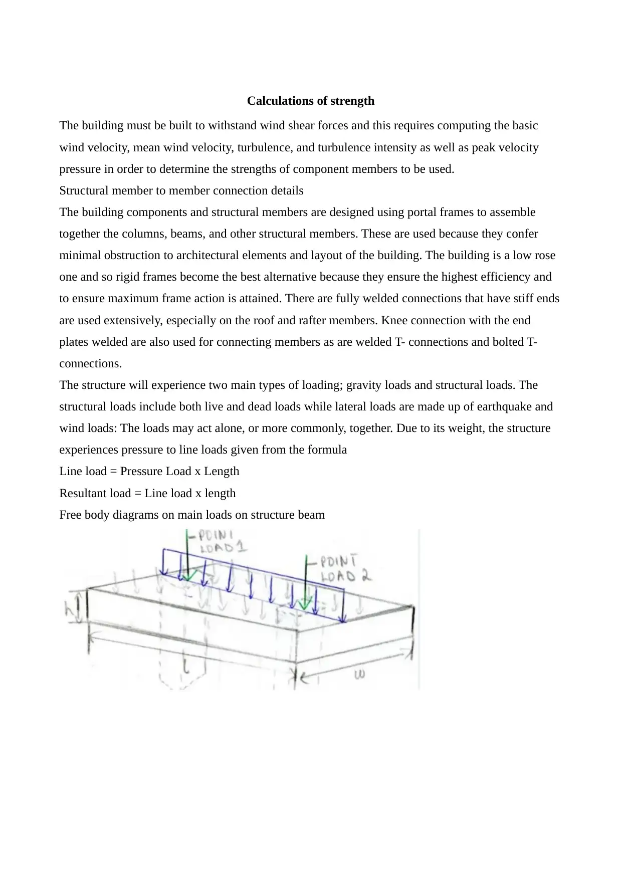
The structure will experience two main types of loading; gravity loads and structural loads. The
structural loads include both live and dead loads while lateral loads are made up of earthquake and
wind loads: The loads may act alone, or more commonly, together. Due to its weight, the structure
experiences pressure to line loads given from the formula
Line load = Pressure Load x Length
Resultant load = Line load x length
Free body diagrams on main loads on structure beam
The building must be built to withstand wind shear forces and this requires computing the basic
wind velocity, mean wind velocity, turbulence, and turbulence intensity as well as peak velocity
pressure in order to determine the strengths of component members to be used.
Structural member to member connection details
The building components and structural members are designed using portal frames to assemble
together the columns, beams, and other structural members. These are used because they confer
minimal obstruction to architectural elements and layout of the building. The building is a low rose
one and so rigid frames become the best alternative because they ensure the highest efficiency and
to ensure maximum frame action is attained. There are fully welded connections that have stiff ends
are used extensively, especially on the roof and rafter members. Knee connection with the end
plates welded are also used for connecting members as are welded T- connections and bolted T-
connections.
The structure will experience two main types of loading; gravity loads and structural loads. The
structural loads include both live and dead loads while lateral loads are made up of earthquake and
wind loads: The loads may act alone, or more commonly, together. Due to its weight, the structure
experiences pressure to line loads given from the formula
Line load = Pressure Load x Length
Resultant load = Line load x length
Free body diagrams on main loads on structure beam
⊘ This is a preview!⊘
Do you want full access?
Subscribe today to unlock all pages.
Trusted by 1+ million students worldwide
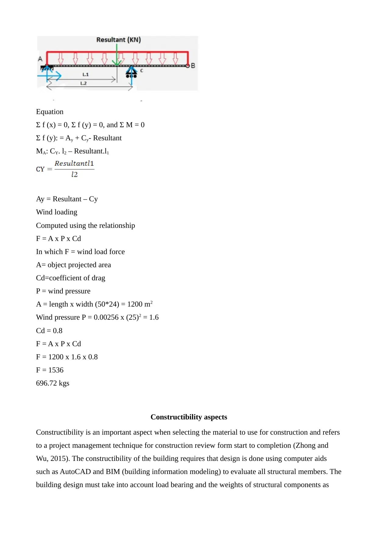
Equation
Σ f (x) = 0, Σ f (y) = 0, and Σ M = 0
Σ f (y): = Ay + Cy- Resultant
MA: CY. l2 – Resultant.l1
Ay = Resultant – Cy
Wind loading
Computed using the relationship
F = A x P x Cd
In which F = wind load force
A= object projected area
Cd=coefficient of drag
P = wind pressure
A = length x width (50*24) = 1200 m2
Wind pressure P = 0.00256 x (25)2 = 1.6
Cd = 0.8
F = A x P x Cd
F = 1200 x 1.6 x 0.8
F = 1536
696.72 kgs
Constructibility aspects
Constructibility is an important aspect when selecting the material to use for construction and refers
to a project management technique for construction review form start to completion (Zhong and
Wu, 2015). The constructibility of the building requires that design is done using computer aids
such as AutoCAD and BIM (building information modeling) to evaluate all structural members. The
building design must take into account load bearing and the weights of structural components as
Paraphrase This Document
Need a fresh take? Get an instant paraphrase of this document with our AI Paraphraser
well as wind and wind shear forces. Using tools such as BIM ensures these are captured and a
building designed efficiently, considering its entire life span (Wang, Chan and Zhang, 2016; Emmitt
and Gorse, 2010).
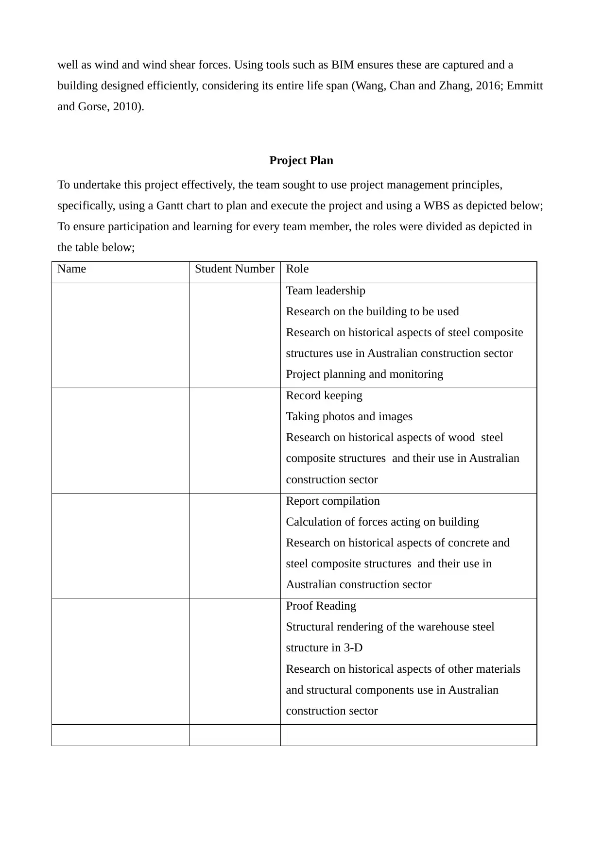
Project Plan
To undertake this project effectively, the team sought to use project management principles,
specifically, using a Gantt chart to plan and execute the project and using a WBS as depicted below;
To ensure participation and learning for every team member, the roles were divided as depicted in
the table below;
Name Student Number Role
Team leadership
Research on the building to be used
Research on historical aspects of steel composite
structures use in Australian construction sector
Project planning and monitoring
Record keeping
Taking photos and images
Research on historical aspects of wood steel
composite structures and their use in Australian
construction sector
Report compilation
Calculation of forces acting on building
Research on historical aspects of concrete and
steel composite structures and their use in
Australian construction sector
Proof Reading
Structural rendering of the warehouse steel
structure in 3-D
Research on historical aspects of other materials
and structural components use in Australian
construction sector
building designed efficiently, considering its entire life span (Wang, Chan and Zhang, 2016; Emmitt
and Gorse, 2010).
Project Plan
To undertake this project effectively, the team sought to use project management principles,
specifically, using a Gantt chart to plan and execute the project and using a WBS as depicted below;
To ensure participation and learning for every team member, the roles were divided as depicted in
the table below;
Name Student Number Role
Team leadership
Research on the building to be used
Research on historical aspects of steel composite
structures use in Australian construction sector
Project planning and monitoring
Record keeping
Taking photos and images
Research on historical aspects of wood steel
composite structures and their use in Australian
construction sector
Report compilation
Calculation of forces acting on building
Research on historical aspects of concrete and
steel composite structures and their use in
Australian construction sector
Proof Reading
Structural rendering of the warehouse steel
structure in 3-D
Research on historical aspects of other materials
and structural components use in Australian
construction sector
Report
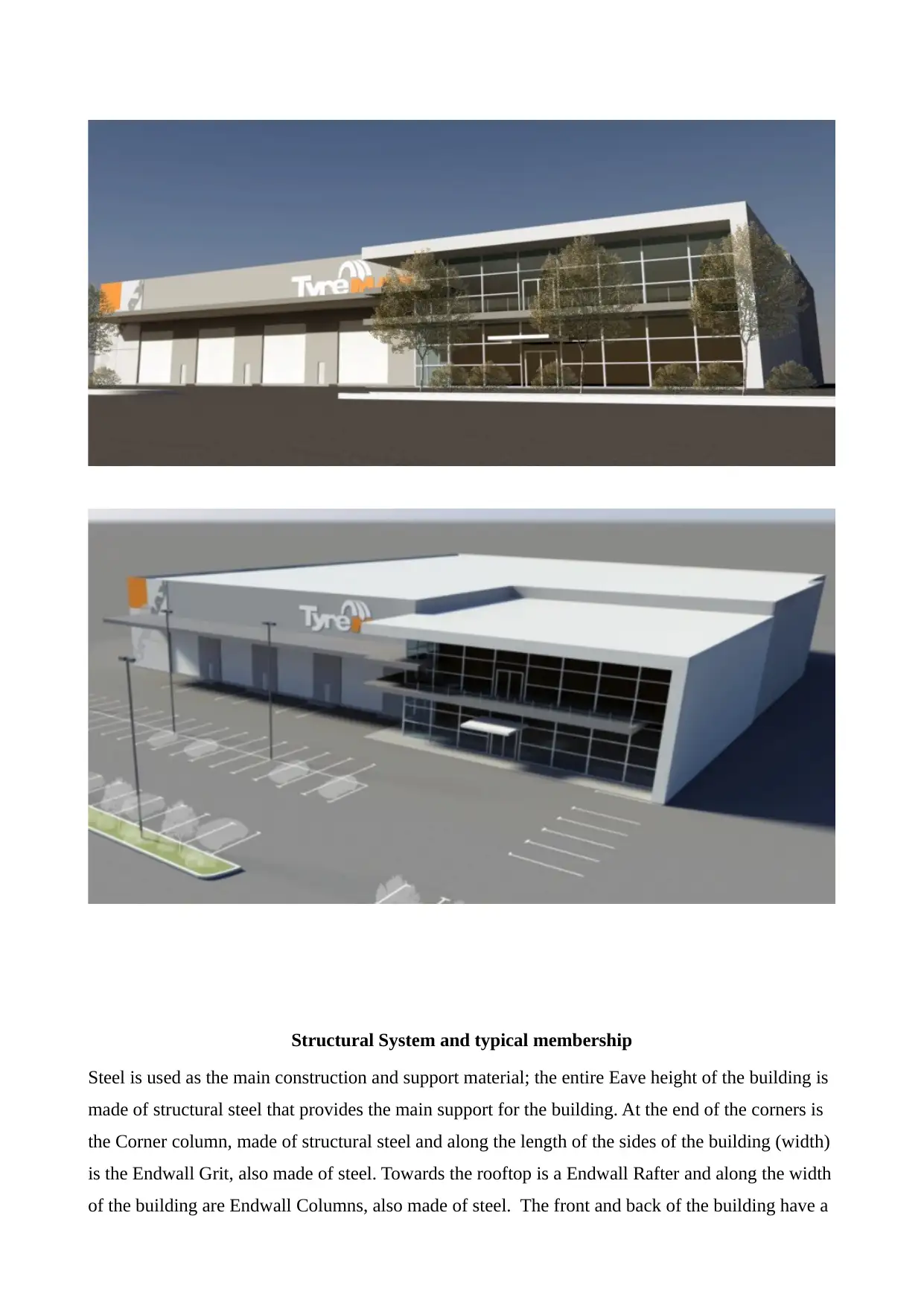
The Analysis of the Building
The analysis of the Tyremax Building was done both visually and using computers, where the visual
structural analysis resulted in the main frame of the building being reproduced using computer
aided software. Based on the initial visual analysis (from observation and images taken), the team
concludes that the general structure of the Tyrmemax building is a portal steel structural frame as
the structure spans between supports and relies on fixed joints having the capability to resist
moments where the horizontal trusses meet with the the vertical supports . The materials used in the
building is mainly galvanized steel with reinforced concrete, especially in the construction of the
floor (suspended floor where the offices are located). The joints are very strong and rigid and can
absorb bending forces, especially those due to wind loading. The forces on the joints (moments)
from the roof rafters can be very strong and so some of that force is transferred to the columns and
as such, the rafter sizes can be reduced and the span increased. The portal frame as used in the
building ensures high strength and efficient in terms of construction and materials use for wide span
buildings as the Tyremax Building. Typically, warehouses are constructed using portal frames and
are also suitable for low rise or single storey buildings and where the floors are not spanning the
entire length of the building for multiple or more than a single storey building as in the Tyremax
building. The buildings 3-D rendering is illustrated in the figure below;
⊘ This is a preview!⊘
Do you want full access?
Subscribe today to unlock all pages.
Trusted by 1+ million students worldwide
1 out of 28
Related Documents


Your All-in-One AI-Powered Toolkit for Academic Success.
+13062052269
info@desklib.com
Available 24*7 on WhatsApp / Email
![[object Object]](/_next/static/media/star-bottom.7253800d.svg)
Unlock your academic potential
Copyright © 2020–2026 A2Z Services. All Rights Reserved. Developed and managed by ZUCOL.