University of Portsmouth: U22293 Concrete Report - Testing Properties
VerifiedAdded on 2023/04/22
|16
|2506
|328
Report
AI Summary
This lab report details a concrete experiment conducted to assess the properties of fresh and hardened concrete. The experiment involved creating concrete mixes with varying water content, testing for slump, density, compressive strength, tensile strength, and flexural strength. The report outlines the materials used (cement, sand, aggregate, and water), the mixing procedures, and the casting of cubes and cylinders for testing. It includes detailed results of slump tests, compressive strength tests at 7, 14, and 28 days, and tensile strength tests. The analysis focuses on the relationship between water/cement ratio and various concrete properties. The discussion section explains the effects of water content on slump, density, compressive strength, flexural strength, and splitting tensile strength. The report concludes that a lower water/cement ratio generally leads to higher compressive, flexural, and tensile strengths, while a higher water content increases the slump. The report also includes calculations and graphical representations of the results.
Running head: LAB REPORT 1
Soil and Materials 1/ U22293
First Name Last Name
Institution
Soil and Materials 1/ U22293
First Name Last Name
Institution
Paraphrase This Document
Need a fresh take? Get an instant paraphrase of this document with our AI Paraphraser
LAB REPORT 2
INTRODUCTION
During the process of making concrete for any construction work, it very important to
employ the suitable concrete mixing ratio since this will enable the construction teams to achieve
a very strong and highly durable concrete mix. During the concrete mix there are four very
significant materials required that is sand, cement, aggregate as well as water (Abrams, 2010). A
concrete mixture ratio of 1 part cement, 3 parts sand, and 3 parts aggregate will produce a
concrete mix of approximately 3000 psi. After the mixing there need to be curing of the concrete
to ensure that the resultant of the concrete. The curing may include the pouring water, using
steels among others (Materials, 2010). This can be done through flow test on fresh concrete
which is out according to BS EN 12350-5. After preparing trial mixes, the mounds were filled
with concrete in three layers, each layer being compacted using a standard rounded rod to
remove as much entrapped air as possible and to produce full compaction of concrete without
segregation Some of the aims of this experiment is given as below;
Aims of the experiment
To describe methods of testing concrete
To discuss the properties of fresh and hardened concrete and their dependence on the mix
proportions
Procedure
Preparations of both cubic and cylindrical concrete moulds
LAB REPORT 3
The moulds surfaces were first cleaned and oiled on their inside surfaces to prevent development
of bond between the mould and the concrete (Joseph, 2013). The moulds were then assembled
and tightened with bolts and nuts to prevent leakage of cement paste and to avoid the plastic
concrete from dismantling during the vibration process while using the vibrator machine (Bartos,
2013).
Preparation of concrete
The ingredients were poured into a clean earth surface starting with ballast, sand and then cement
in the right mix proportions for the respective mix designs. Mixing was done with a spade for
about 5 minutes, after that, water was poured as the mixing continues at control intervals to avoid
excess water into the mix (Klieger, 2014).
After mixing all the ingredients, they were tested while still plastic, put in the moulds to dry and
harden for 24 hours before curing them in a basin of water.
Casting of cubes and cylinders
The cube specimens were cast in iron moulds generally 100x100x100mm for cubes and cylinder
moulds of height 300mm by 150mm diameter, which conforms to the specifications of BS 1881-
3:1970.
After preparing trial mixes, the moulds were filled with concrete in three layers, each layer being
compacted using a standard rounded rod to remove as much entrapped air as possible and to
produce full compaction of concrete without segregation (Marrs, 2012). The moulds were filled
to overflowing and excess concrete removed by scraping off the surface of the moulds.
The test specimens were then left in the moulds undisturbed for 24 hours and protected against
shock, vibration and dehydration.
⊘ This is a preview!⊘
Do you want full access?
Subscribe today to unlock all pages.

Trusted by 1+ million students worldwide
LAB REPORT 4
De-molding the cast concrete cubes and cylinders
The cast cubes and cylinders were left in the moulds for 24 hours and then they were de-molded.
De-molding is done after setting of the concrete as shown in figure 10.
Before placing the cast cubes and cylinders in the water basin, they were marked with a water
proof chalk.
Curing of concrete
The cast cubes and cylinders after being de-molded are left in a water basin with the aim of
keeping the concrete saturated so that there is adequate water for the hydration of cement and
also to prevent shrinkage cracking as shown in figure 11 (Marrs, 2012). The cubes were cured
for 28days.
FLOW TEST
To study the workability of different concrete mixes, flow test on fresh concrete was carried out
according to BS EN 12350-5.
Slump test
The test moulds used to do the slump test consists of a cone frustum 300mm high and is placed
on a smooth surface and filled with concrete in 3 layers each being tampered 25 times with a
standard rod with a rounded end (Tamimi, 2013).
The excess concrete is scraped off the surface and the cone is slowly lifted up. The height of the
slump is noted down and compared with the height of the cone initially. The decrease in height
was the slump height and was noted.
TESTS FOR THE COMPRESSIVE STRENGTH OF CONCRETE
Paraphrase This Document
Need a fresh take? Get an instant paraphrase of this document with our AI Paraphraser
LAB REPORT 5
For each mix design, eight cubic was prepared and their compressive strength tested at 7, 14, and
28 days of age after pouring in accordance to BS 1881-116:1983
The cubes were loaded to failure to check their failure loads from the testing machine as shown
in figure 12, using the failure loads the compressive strengths (𝜎) were calculated (Harrison,
2013).
Before putting the cubes in the machine, they were removed from the water basin and left to dry
for about 10 minutes.
100x100x100 cubes millimeter was used for a maximum aggregate size 10mm, placed accurately
in the testing machine, the machine was switched on and the cubes were then held on two faces
and loaded until failure and the failure loads (F) noted down. Therefore, the value of 𝜎 was
determined by equation shown below.
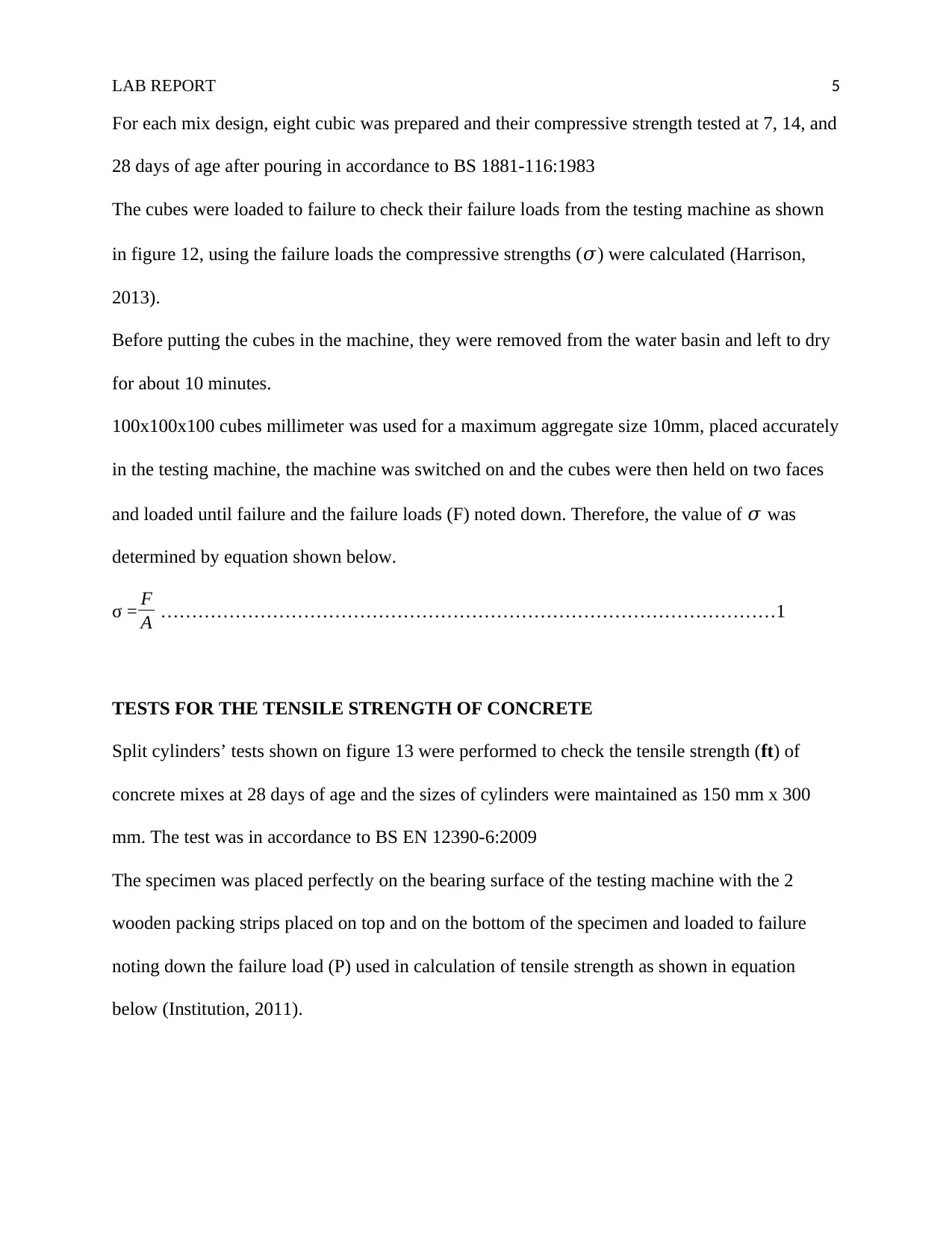
σ = F
A ………………………………………………………………………………………1
TESTS FOR THE TENSILE STRENGTH OF CONCRETE
Split cylinders’ tests shown on figure 13 were performed to check the tensile strength (ft) of
concrete mixes at 28 days of age and the sizes of cylinders were maintained as 150 mm x 300
mm. The test was in accordance to BS EN 12390-6:2009
The specimen was placed perfectly on the bearing surface of the testing machine with the 2
wooden packing strips placed on top and on the bottom of the specimen and loaded to failure
noting down the failure load (P) used in calculation of tensile strength as shown in equation
below (Institution, 2011).
LAB REPORT 6
f t= 2 P
A …………………………………………………………………………………………2
RESULTS AND ANALYSIS
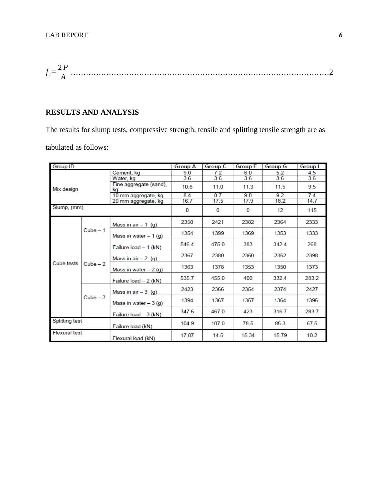
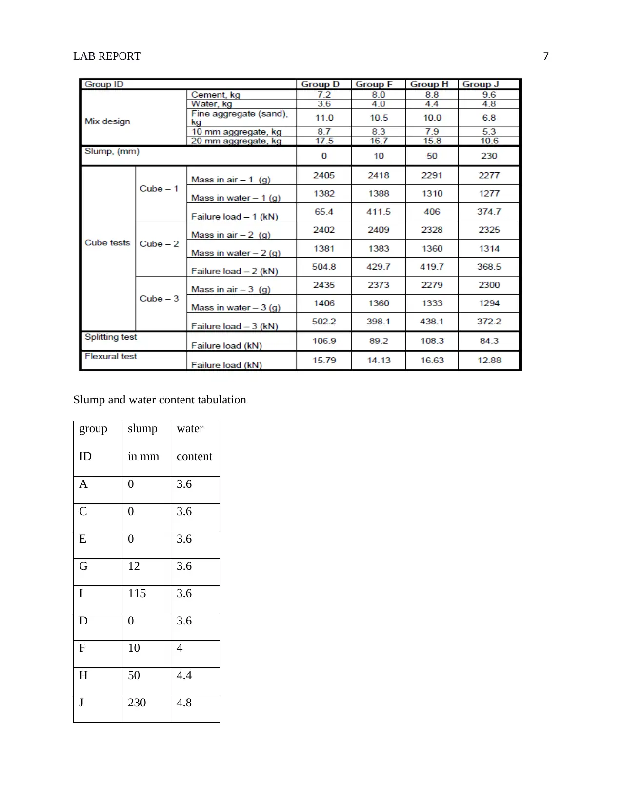
The results for slump tests, compressive strength, tensile and splitting tensile strength are as
tabulated as follows:
f t= 2 P
A …………………………………………………………………………………………2
RESULTS AND ANALYSIS
The results for slump tests, compressive strength, tensile and splitting tensile strength are as
tabulated as follows:
⊘ This is a preview!⊘
Do you want full access?
Subscribe today to unlock all pages.

Trusted by 1+ million students worldwide
LAB REPORT 7
Slump and water content tabulation
group
ID
slump
in mm
water
content
A 0 3.6
C 0 3.6
E 0 3.6
G 12 3.6
I 115 3.6
D 0 3.6
F 10 4
H 50 4.4
J 230 4.8
Slump and water content tabulation
group
ID
slump
in mm
water
content
A 0 3.6
C 0 3.6
E 0 3.6
G 12 3.6
I 115 3.6
D 0 3.6
F 10 4
H 50 4.4
J 230 4.8
Paraphrase This Document
Need a fresh take? Get an instant paraphrase of this document with our AI Paraphraser
LAB REPORT 8
3.4 3.6 3.8 4 4.2 4.4 4.6 4.8 5
0
50
100
150
200
250
slump in mm
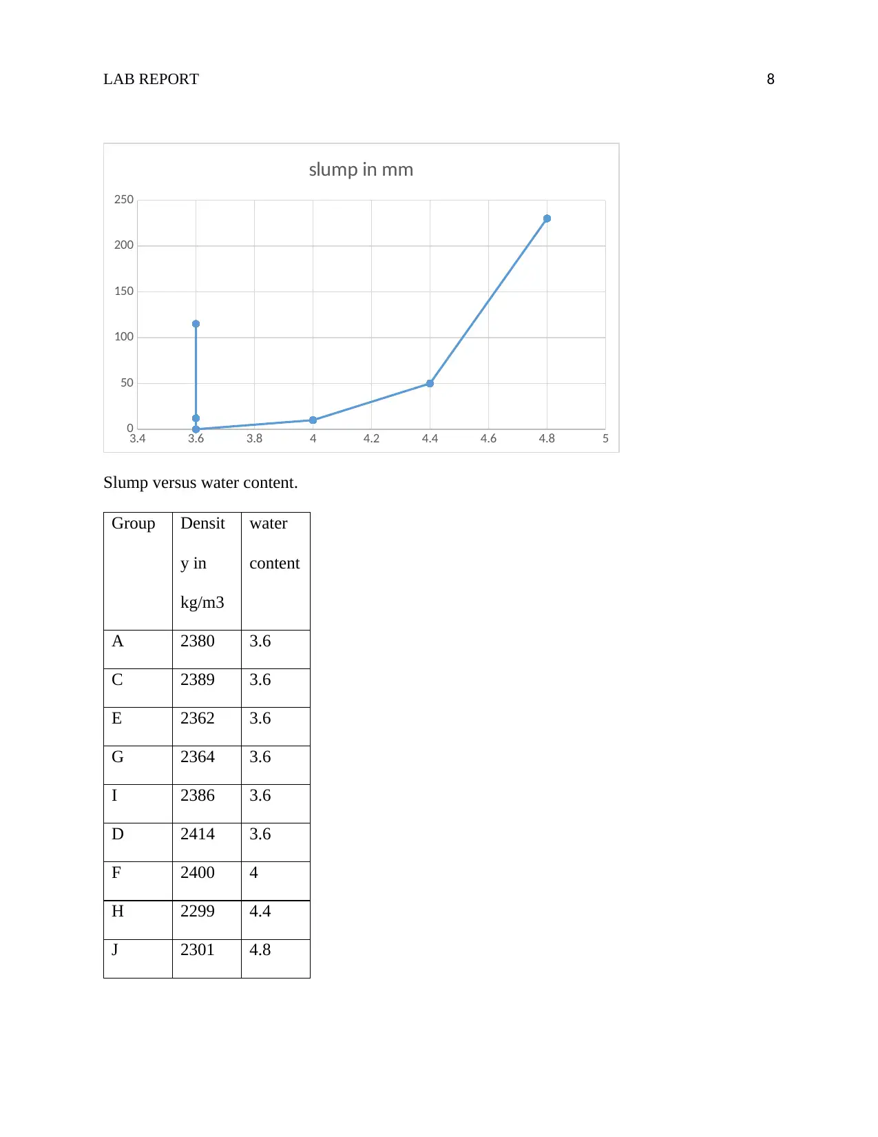
Slump versus water content.
Group Densit
y in
kg/m3
water
content
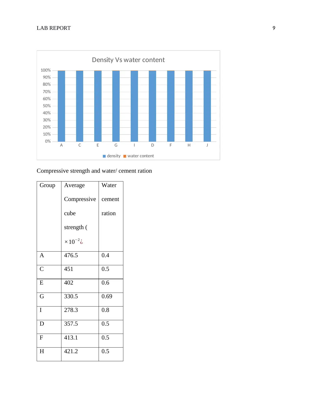
A 2380 3.6
C 2389 3.6
E 2362 3.6
G 2364 3.6
I 2386 3.6
D 2414 3.6
F 2400 4
H 2299 4.4
J 2301 4.8
3.4 3.6 3.8 4 4.2 4.4 4.6 4.8 5
0
50
100
150
200
250
slump in mm
Slump versus water content.
Group Densit
y in
kg/m3
water
content
A 2380 3.6
C 2389 3.6
E 2362 3.6
G 2364 3.6
I 2386 3.6
D 2414 3.6
F 2400 4
H 2299 4.4
J 2301 4.8
LAB REPORT 9
A C E G I D F H J
0%
10%
20%
30%
40%
50%
60%
70%
80%
90%
100%
Density Vs water content
density water content
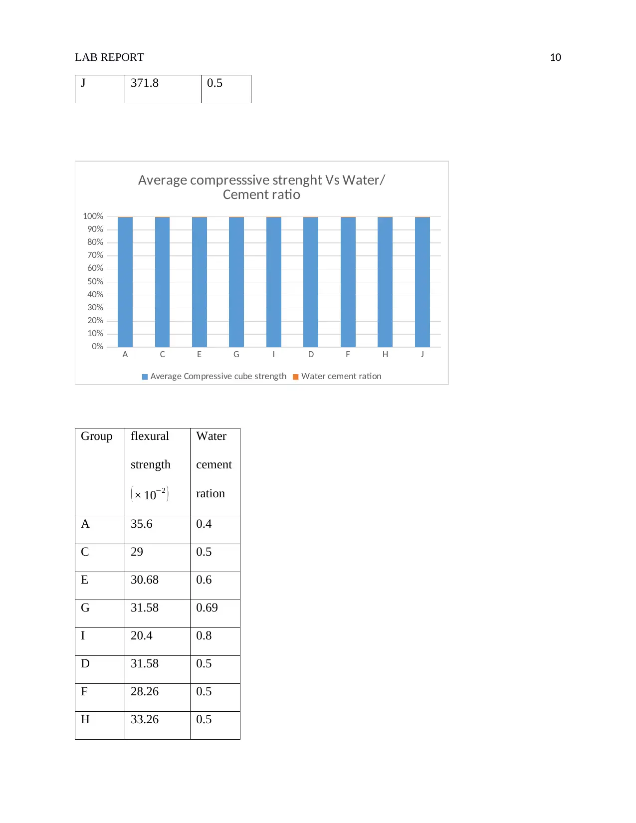
Compressive strength and water/ cement ration
Group Average
Compressive
cube
strength (
×10−2 ¿
Water
cement
ration
A 476.5 0.4
C 451 0.5
E 402 0.6
G 330.5 0.69
I 278.3 0.8
D 357.5 0.5
F 413.1 0.5
H 421.2 0.5
⊘ This is a preview!⊘
Do you want full access?
Subscribe today to unlock all pages.

Trusted by 1+ million students worldwide
LAB REPORT 10
J 371.8 0.5
A C E G I D F H J
0%
10%
20%
30%
40%
50%
60%
70%
80%
90%
100%
Average compresssive strenght Vs Water/
Cement ratio
Average Compressive cube strength Water cement ration
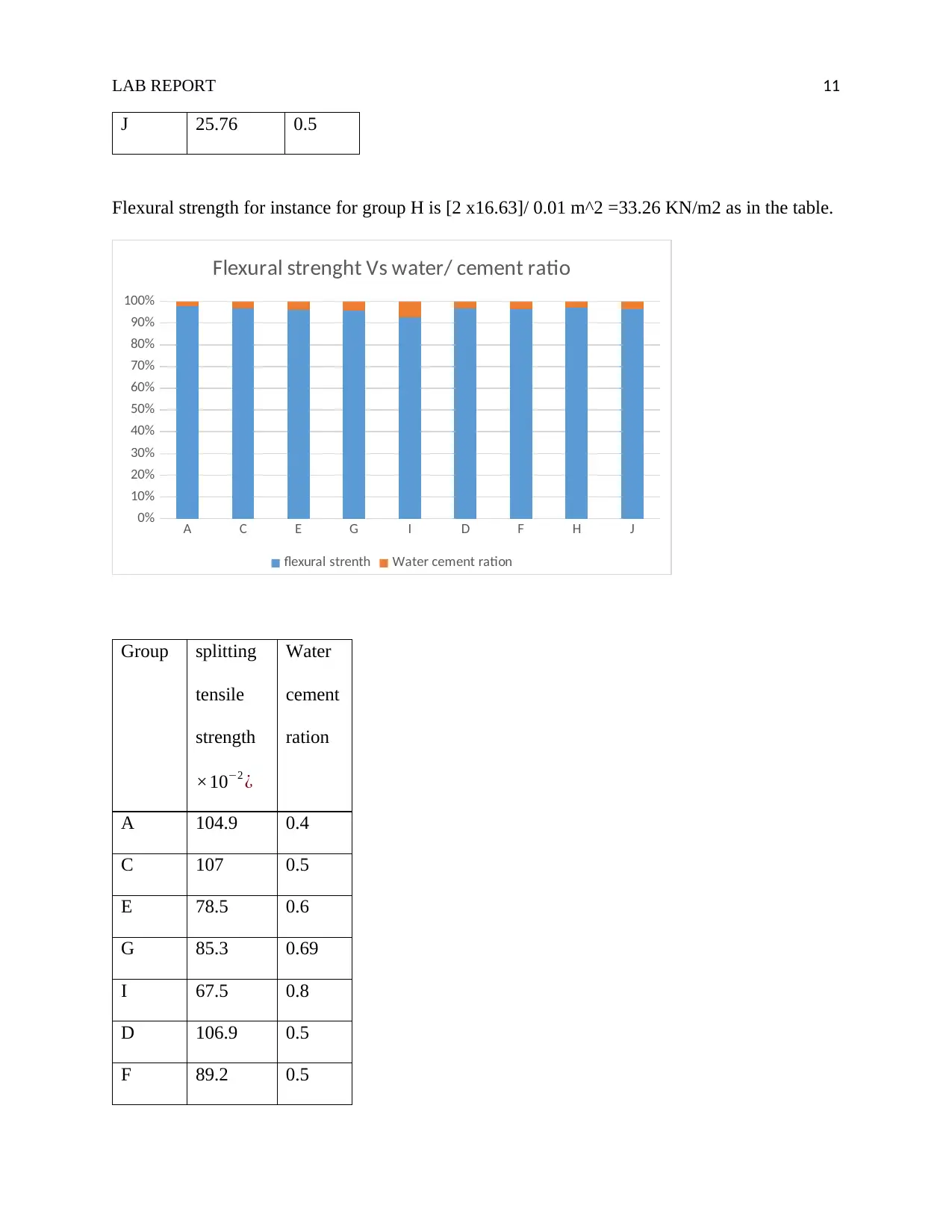
Group flexural
strength
( × 10−2 )
Water
cement
ration
A 35.6 0.4
C 29 0.5
E 30.68 0.6
G 31.58 0.69
I 20.4 0.8
D 31.58 0.5
F 28.26 0.5
H 33.26 0.5
Paraphrase This Document
Need a fresh take? Get an instant paraphrase of this document with our AI Paraphraser
LAB REPORT 11
J 25.76 0.5
Flexural strength for instance for group H is [2 x16.63]/ 0.01 m^2 =33.26 KN/m2 as in the table.
A C E G I D F H J
0%
10%
20%
30%
40%
50%
60%
70%
80%
90%
100%
Flexural strenght Vs water/ cement ratio
flexural strenth Water cement ration
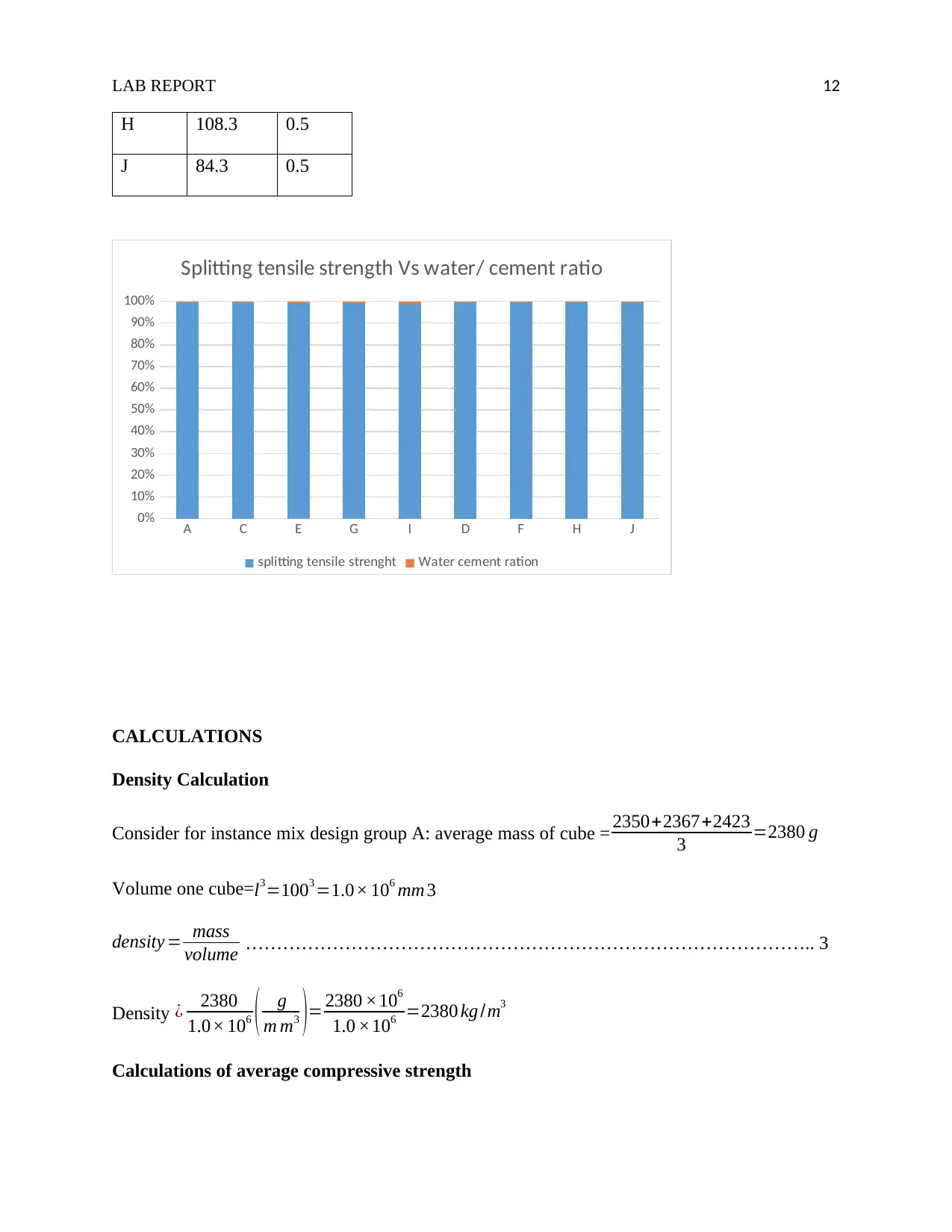
Group splitting
tensile
strength
×10−2 ¿
Water
cement
ration
A 104.9 0.4
C 107 0.5
E 78.5 0.6
G 85.3 0.69
I 67.5 0.8
D 106.9 0.5
F 89.2 0.5
LAB REPORT 12
H 108.3 0.5
J 84.3 0.5
A C E G I D F H J
0%
10%
20%
30%
40%
50%
60%
70%
80%
90%
100%
Splitting tensile strength Vs water/ cement ratio
splitting tensile strenght Water cement ration
CALCULATIONS
Density Calculation
Consider for instance mix design group A: average mass of cube = 2350+2367+2423
3 =2380 g
Volume one cube=l3=1003 =1.0× 106 mm 3
density = mass
volume ……………………………………………………………………………….. 3
Density ¿ 2380
1.0× 10⁶ ( g
m m3 )= 2380 ×106
1.0 ×106 =2380 kg /m3
Calculations of average compressive strength
⊘ This is a preview!⊘
Do you want full access?
Subscribe today to unlock all pages.

Trusted by 1+ million students worldwide
1 out of 16
Related Documents
Your All-in-One AI-Powered Toolkit for Academic Success.
+13062052269
info@desklib.com
Available 24*7 on WhatsApp / Email
![[object Object]](/_next/static/media/star-bottom.7253800d.svg)
Unlock your academic potential
Copyright © 2020–2026 A2Z Services. All Rights Reserved. Developed and managed by ZUCOL.


