Conceptual Design of UAV Wings
VerifiedAdded on 2020/03/02
|14
|3297
|447
Report
AI Summary
This report presents a comprehensive analysis of the conceptual design of medium-sized wings for Unmanned Aerial Vehicles (UAVs). It covers aerodynamic computational analysis, structural load analysis, and the design methodologies necessary for effective UAV operation. The report discusses the advantages and disadvantages of various wing designs, outlines the system requirements, and provides recommendations for future design improvements. Through detailed examination of existing research and theoretical frameworks, the report aims to enhance the understanding of UAV wing design and its applications in civil and military operations.
System Science And Engineering
Paraphrase This Document
Need a fresh take? Get an instant paraphrase of this document with our AI Paraphraser
Abstract
The UAV (Unmanned Aerial Vehicles) has many applications in the field of civil and special
operations in military. These vehicles are applied especially in the dull, dirty and dangerous
mission. According to the performance rate, cost of the maintenance, design and efficiency is
decided. The main aim of this report is to analyze the conceptual design of the medium sized
wings type surveillance UAV. To achieve this aim two important sessions are provided such as
aerodynamic computational analysis and the structural load analysis. In this analysis, some
existing research work is carried out by analyzing the required materials and with appropriate
methodologies. The theoretical research on aerodynamics, design methodologies of the aircraft
structure is studied and the results are compared with the historical wing design trends. In the
preliminary design, the requirements of load and design lift are calculated. The advantages and
the disadvantages of the wing design are discussed in detail.
Table of Contents
Abstract......................................................................................................................................................1
1. Introduction.......................................................................................................................................3
2. Needs definition.................................................................................................................................3
3. Conceptual design..............................................................................................................................4
3.1 Problem Definition.....................................................................................................................4
3.2 System Requirement..................................................................................................................4
3.3 Preliminary System Design.......................................................................................................5
3.4 Detailed system design development........................................................................................5
4. Analysis..............................................................................................................................................7
5. Structural Analysis............................................................................................................................9
6. Recommendation.............................................................................................................................10
7. Conclusion........................................................................................................................................10
References................................................................................................................................................11
⊘ This is a preview!⊘
Do you want full access?
Subscribe today to unlock all pages.
Trusted by 1+ million students worldwide
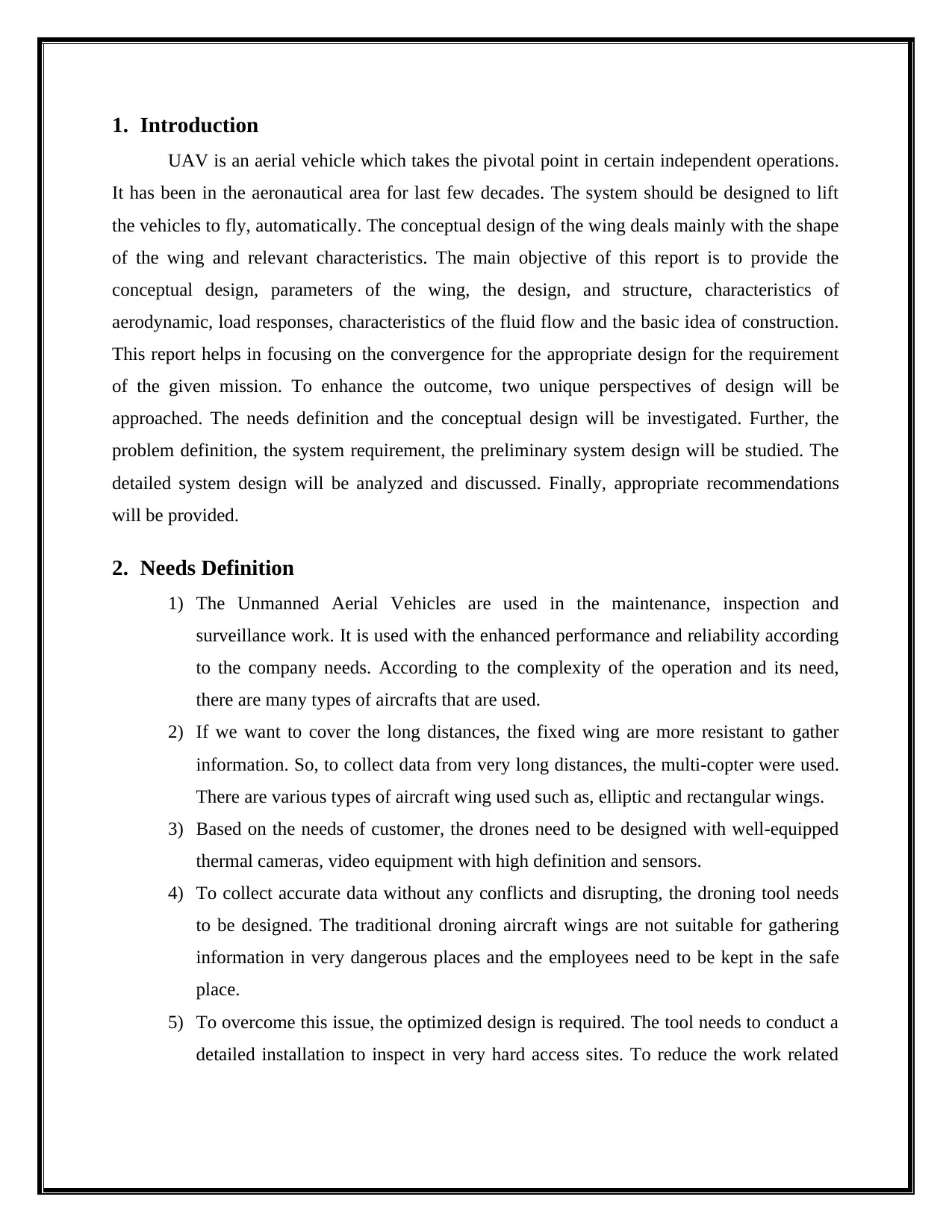
1. Introduction
UAV is an aerial vehicle which takes the pivotal point in certain independent operations.
It has been in the aeronautical area for last few decades. The system should be designed to lift
the vehicles to fly, automatically. The conceptual design of the wing deals mainly with the shape
of the wing and relevant characteristics. The main objective of this report is to provide the
conceptual design, parameters of the wing, the design, and structure, characteristics of
aerodynamic, load responses, characteristics of the fluid flow and the basic idea of construction.
This report helps in focusing on the convergence for the appropriate design for the requirement
of the given mission. To enhance the outcome, two unique perspectives of design will be
approached. The needs definition and the conceptual design will be investigated. Further, the
problem definition, the system requirement, the preliminary system design will be studied. The
detailed system design will be analyzed and discussed. Finally, appropriate recommendations
will be provided.
2. Needs Definition
1) The Unmanned Aerial Vehicles are used in the maintenance, inspection and
surveillance work. It is used with the enhanced performance and reliability according
to the company needs. According to the complexity of the operation and its need,
there are many types of aircrafts that are used.
2) If we want to cover the long distances, the fixed wing are more resistant to gather
information. So, to collect data from very long distances, the multi-copter were used.
There are various types of aircraft wing used such as, elliptic and rectangular wings.
3) Based on the needs of customer, the drones need to be designed with well-equipped
thermal cameras, video equipment with high definition and sensors.
4) To collect accurate data without any conflicts and disrupting, the droning tool needs
to be designed. The traditional droning aircraft wings are not suitable for gathering
information in very dangerous places and the employees need to be kept in the safe
place.
5) To overcome this issue, the optimized design is required. The tool needs to conduct a
detailed installation to inspect in very hard access sites. To reduce the work related
Paraphrase This Document
Need a fresh take? Get an instant paraphrase of this document with our AI Paraphraser
costs, the rectangular aircraft wings are required for better predictive planning (SNCF
Réseau, 2017).
3. Conceptual Design
3.1 Problem Definition
The main objective is to provide the conceptual design analysis for the medium sized
wings type surveillance UAV. According to the definition of UAV, it is the "well-equipped,
more powered aerial vehicle but, it could not carry any human. When simply says it is an
unmanned vehicle" (Agte, Borer and Weck, 2012). It is used for lifting the vehicles to fly on the
sky automatically. The functionalities are based on the preprogrammed plans of the flight plans,
dynamic automation on the complex areas. In traditional droning aircraft wings are not suitable
to collect data from the dangerous places and they didn’t provide any safety precautions for the
employees (Fioriti, 2014). To overcome this problem, the UAV with medium sized rectangular
shaped aircraft wings need to be designed.
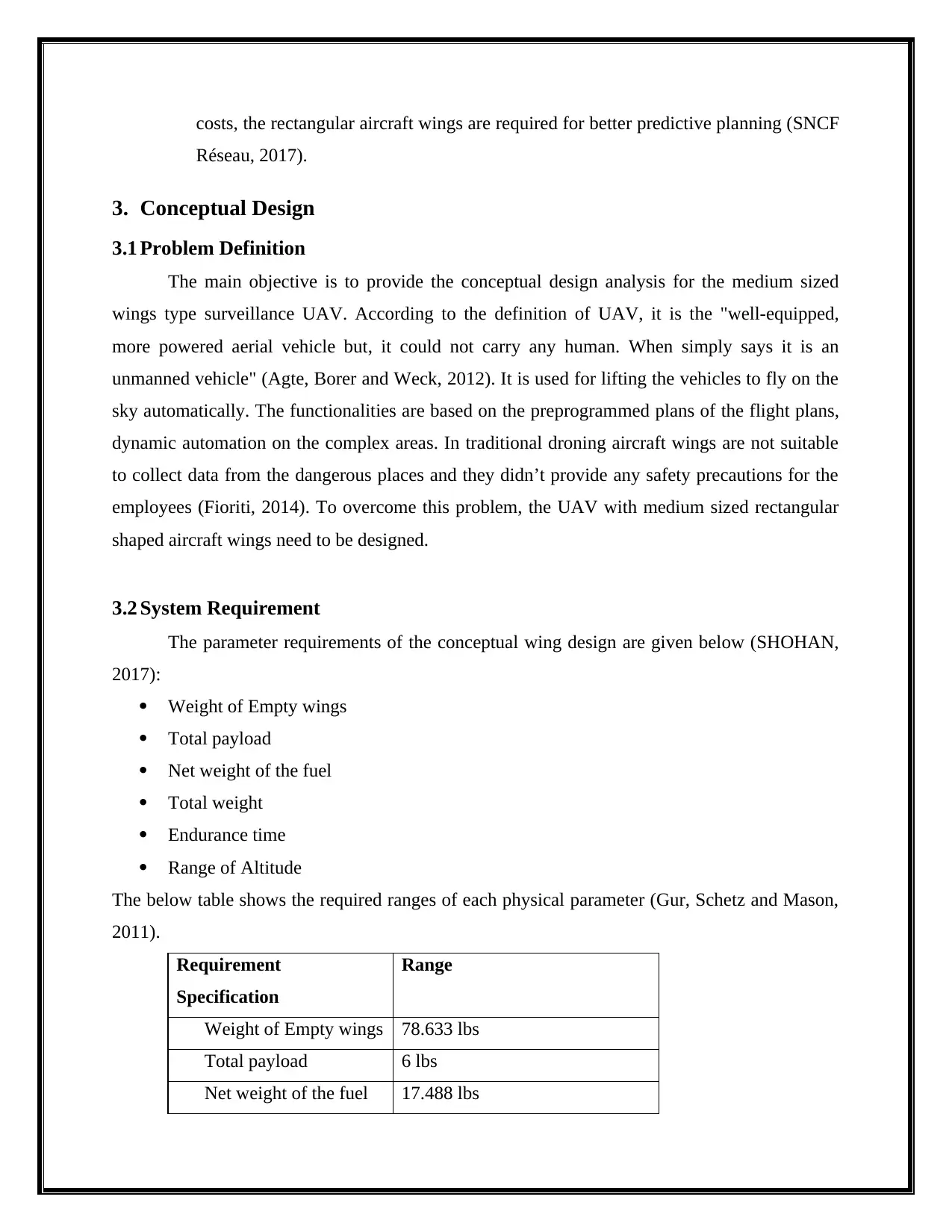
3.2 System Requirement
The parameter requirements of the conceptual wing design are given below (SHOHAN,
2017):
Weight of Empty wings
Total payload
Net weight of the fuel
Total weight
Endurance time
Range of Altitude
The below table shows the required ranges of each physical parameter (Gur, Schetz and Mason,
2011).
Requirement
Specification
Range
Weight of Empty wings 78.633 lbs
Total payload 6 lbs
Net weight of the fuel 17.488 lbs
Réseau, 2017).
3. Conceptual Design
3.1 Problem Definition
The main objective is to provide the conceptual design analysis for the medium sized
wings type surveillance UAV. According to the definition of UAV, it is the "well-equipped,
more powered aerial vehicle but, it could not carry any human. When simply says it is an
unmanned vehicle" (Agte, Borer and Weck, 2012). It is used for lifting the vehicles to fly on the
sky automatically. The functionalities are based on the preprogrammed plans of the flight plans,
dynamic automation on the complex areas. In traditional droning aircraft wings are not suitable
to collect data from the dangerous places and they didn’t provide any safety precautions for the
employees (Fioriti, 2014). To overcome this problem, the UAV with medium sized rectangular
shaped aircraft wings need to be designed.
3.2 System Requirement
The parameter requirements of the conceptual wing design are given below (SHOHAN,
2017):
Weight of Empty wings
Total payload
Net weight of the fuel
Total weight
Endurance time
Range of Altitude
The below table shows the required ranges of each physical parameter (Gur, Schetz and Mason,
2011).
Requirement
Specification
Range
Weight of Empty wings 78.633 lbs
Total payload 6 lbs
Net weight of the fuel 17.488 lbs
Total weight 150 lbs
Endurance time 5.5 km
Range of Altitude 3.5 hrs
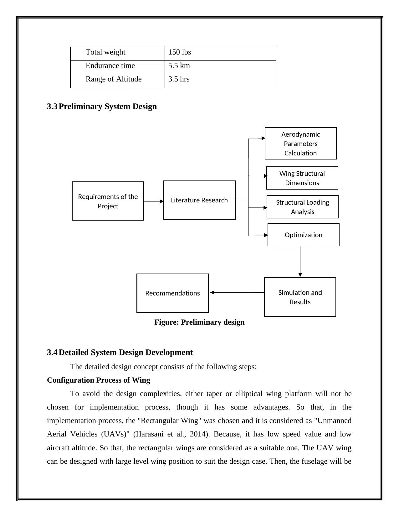
3.3 Preliminary System Design
Figure: Preliminary design
3.4 Detailed System Design Development
The detailed design concept consists of the following steps:
Configuration Process of Wing
To avoid the design complexities, either taper or elliptical wing platform will not be
chosen for implementation process, though it has some advantages. So that, in the
implementation process, the "Rectangular Wing" was chosen and it is considered as "Unmanned
Aerial Vehicles (UAVs)" (Harasani et al., 2014). Because, it has low speed value and low
aircraft altitude. So that, the rectangular wings are considered as a suitable one. The UAV wing
can be designed with large level wing position to suit the design case. Then, the fuselage will be
Requirements of the
Project Literature Research
Aerodynamic
Parameters
Calculation
Wing Structural
Dimensions
Structural Loading
Analysis
Optimization
Simulation and
Results
Recommendations
Endurance time 5.5 km
Range of Altitude 3.5 hrs
3.3 Preliminary System Design
Figure: Preliminary design
3.4 Detailed System Design Development
The detailed design concept consists of the following steps:
Configuration Process of Wing
To avoid the design complexities, either taper or elliptical wing platform will not be
chosen for implementation process, though it has some advantages. So that, in the
implementation process, the "Rectangular Wing" was chosen and it is considered as "Unmanned
Aerial Vehicles (UAVs)" (Harasani et al., 2014). Because, it has low speed value and low
aircraft altitude. So that, the rectangular wings are considered as a suitable one. The UAV wing
can be designed with large level wing position to suit the design case. Then, the fuselage will be
Requirements of the
Project Literature Research
Aerodynamic
Parameters
Calculation
Wing Structural
Dimensions
Structural Loading
Analysis
Optimization
Simulation and
Results
Recommendations
⊘ This is a preview!⊘
Do you want full access?
Subscribe today to unlock all pages.
Trusted by 1+ million students worldwide
differentiated with the mid wing position wherever it is necessary to go though the complexities
in the fuselage mounting and it will be fixed in the center position (Huang, Peng and Jones,
2017). But in reality, the Low featured wings are not used in the UAV. Because they do not have
any additional features and advantages.
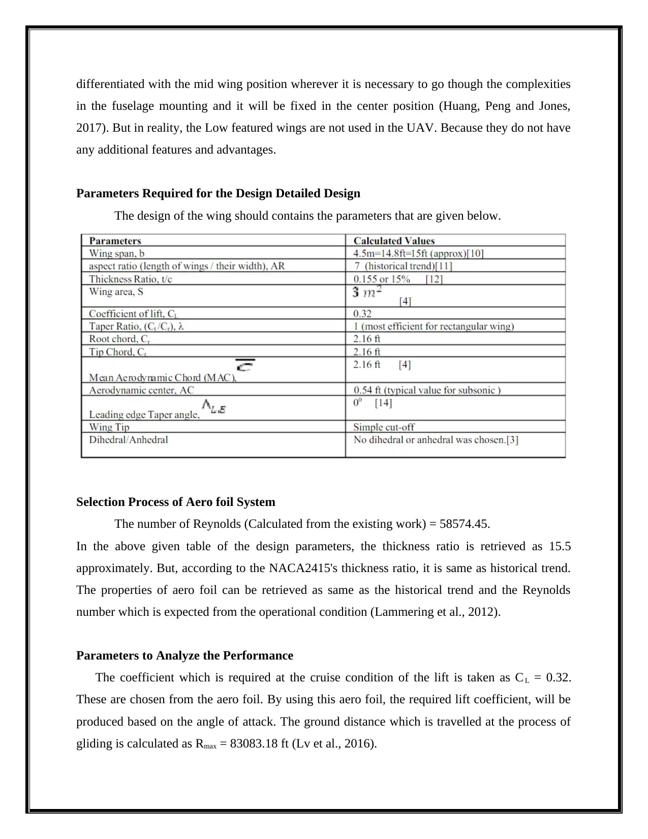
Parameters Required for the Design Detailed Design
The design of the wing should contains the parameters that are given below.
Selection Process of Aero foil System
The number of Reynolds (Calculated from the existing work) = 58574.45.
In the above given table of the design parameters, the thickness ratio is retrieved as 15.5
approximately. But, according to the NACA2415's thickness ratio, it is same as historical trend.
The properties of aero foil can be retrieved as same as the historical trend and the Reynolds
number which is expected from the operational condition (Lammering et al., 2012).
Parameters to Analyze the Performance
The coefficient which is required at the cruise condition of the lift is taken as C L = 0.32.
These are chosen from the aero foil. By using this aero foil, the required lift coefficient, will be
produced based on the angle of attack. The ground distance which is travelled at the process of
gliding is calculated as Rmax = 83083.18 ft (Lv et al., 2016).
in the fuselage mounting and it will be fixed in the center position (Huang, Peng and Jones,
2017). But in reality, the Low featured wings are not used in the UAV. Because they do not have
any additional features and advantages.
Parameters Required for the Design Detailed Design
The design of the wing should contains the parameters that are given below.
Selection Process of Aero foil System
The number of Reynolds (Calculated from the existing work) = 58574.45.
In the above given table of the design parameters, the thickness ratio is retrieved as 15.5
approximately. But, according to the NACA2415's thickness ratio, it is same as historical trend.
The properties of aero foil can be retrieved as same as the historical trend and the Reynolds
number which is expected from the operational condition (Lammering et al., 2012).
Parameters to Analyze the Performance
The coefficient which is required at the cruise condition of the lift is taken as C L = 0.32.
These are chosen from the aero foil. By using this aero foil, the required lift coefficient, will be
produced based on the angle of attack. The ground distance which is travelled at the process of
gliding is calculated as Rmax = 83083.18 ft (Lv et al., 2016).
Paraphrase This Document
Need a fresh take? Get an instant paraphrase of this document with our AI Paraphraser
Surfaces of Control with Geometry of High Lift Devices
Generally, the high lift devices are aircraft components. The main purpose of using these
components is to enhance the lifting process. These components can be used with the mechanism
of either static (unmovable) or dynamic (movable). According to the requirements, it will be
deployed based on the mechanisms. The high lift devices are slats and flaps and these are widely
used in various applications. In particular, the flaps and aileron were merged along with the main
wing (Lyu and Martins, 2014).
4. Analysis
In the present work, the structural analysis is used to evaluate some specific parameters
such as stresses, forces and so on. this process can be done under internal and external manner.
generally the structural analysis is classified as two types namely, load distribution on wing and
tubular spar (Saharudin, 2016).
Calculation of Load Distribution on the Wing
Here , the load distribution (McDonald, 2011) is designed by wing beams, so it is
necessary to calculates load value of net beam. which can be calculated by using the following
formula :
q(y) = L(y) - N . gm(y)
Thus the net beam is achevied apporimately as 23.80 lb/ft.
Type of Tubular Spar
Analysis is analzed by using two main different models named, tubular spar with strututre
and the second one is tubular spar without struture (Ng and Willcox, 2016).
Tubular Spar without including the Struture
It is considerd that the load praperly is distributed with the support of wing chords.
Although this is not a quite true as the lift falls off towards the wing tip and the lift loads were
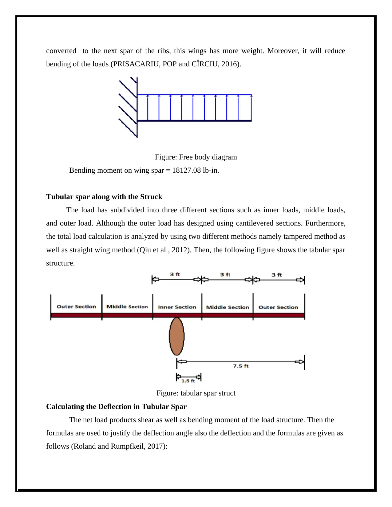
converted to the next spar of the ribs, this wings has more weight. Moreover, it will reduce
bending of the loads (PRISACARIU, POP and CÎRCIU, 2016).
Figure: Free body diagram
Bending moment on wing spar = 18127.08 lb-in.
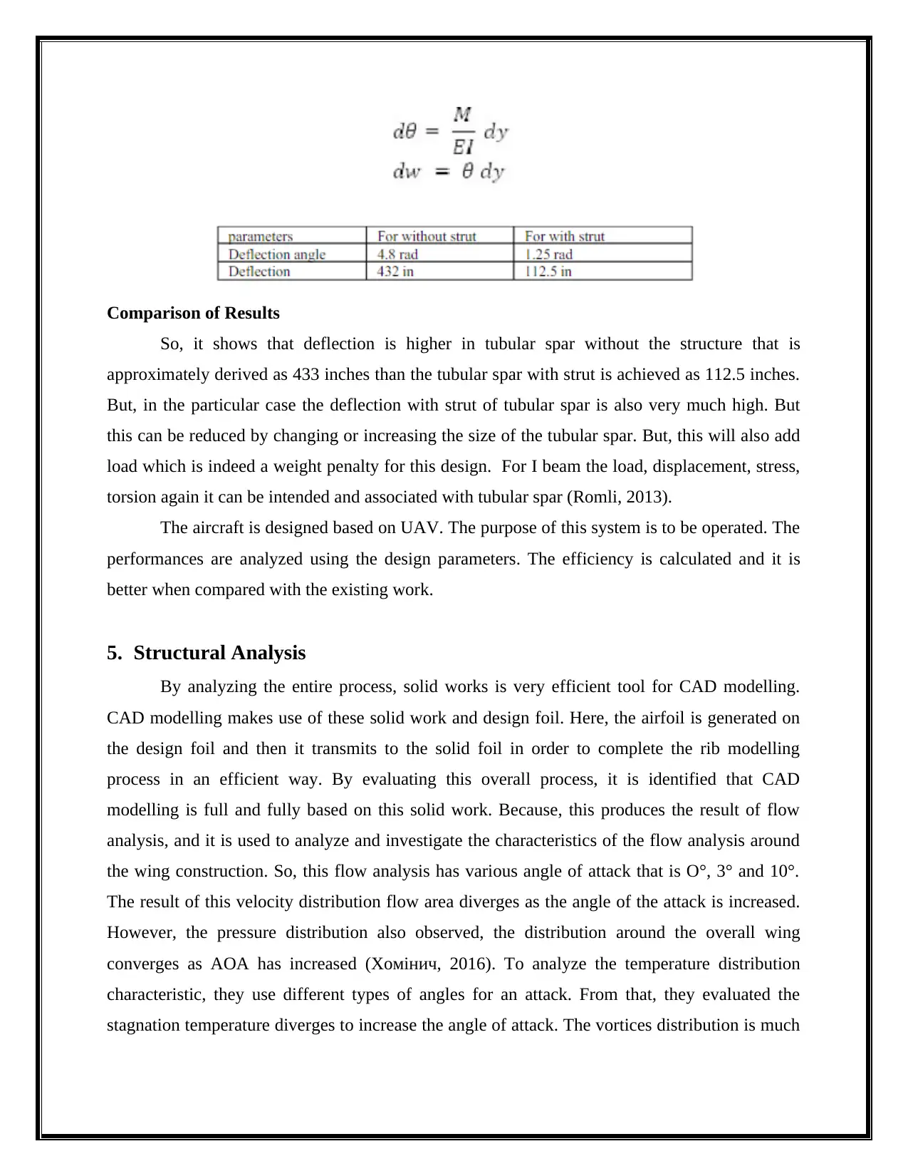
Tubular spar along with the Struck
The load has subdivided into three different sections such as inner loads, middle loads,
and outer load. Although the outer load has designed using cantilevered sections. Furthermore,
the total load calculation is analyzed by using two different methods namely tampered method as
well as straight wing method (Qiu et al., 2012). Then, the following figure shows the tabular spar
structure.
Figure: tabular spar struct
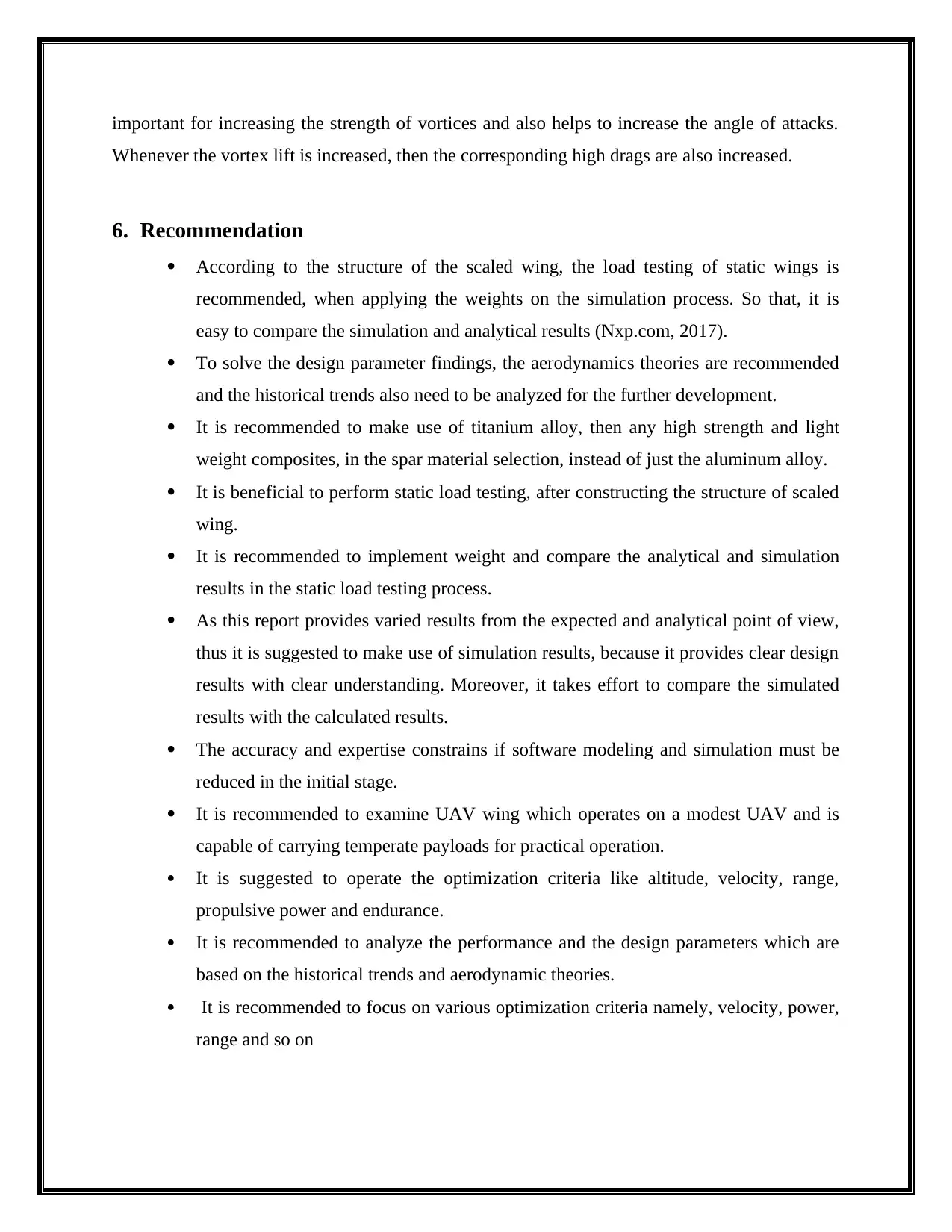
Calculating the Deflection in Tubular Spar
The net load products shear as well as bending moment of the load structure. Then the
formulas are used to justify the deflection angle also the deflection and the formulas are given as
follows (Roland and Rumpfkeil, 2017):
bending of the loads (PRISACARIU, POP and CÎRCIU, 2016).
Figure: Free body diagram
Bending moment on wing spar = 18127.08 lb-in.
Tubular spar along with the Struck
The load has subdivided into three different sections such as inner loads, middle loads,
and outer load. Although the outer load has designed using cantilevered sections. Furthermore,
the total load calculation is analyzed by using two different methods namely tampered method as
well as straight wing method (Qiu et al., 2012). Then, the following figure shows the tabular spar
structure.
Figure: tabular spar struct
Calculating the Deflection in Tubular Spar
The net load products shear as well as bending moment of the load structure. Then the
formulas are used to justify the deflection angle also the deflection and the formulas are given as
follows (Roland and Rumpfkeil, 2017):
⊘ This is a preview!⊘
Do you want full access?
Subscribe today to unlock all pages.
Trusted by 1+ million students worldwide
Comparison of Results
So, it shows that deflection is higher in tubular spar without the structure that is
approximately derived as 433 inches than the tubular spar with strut is achieved as 112.5 inches.
But, in the particular case the deflection with strut of tubular spar is also very much high. But
this can be reduced by changing or increasing the size of the tubular spar. But, this will also add
load which is indeed a weight penalty for this design. For I beam the load, displacement, stress,
torsion again it can be intended and associated with tubular spar (Romli, 2013).
The aircraft is designed based on UAV. The purpose of this system is to be operated. The
performances are analyzed using the design parameters. The efficiency is calculated and it is
better when compared with the existing work.
5. Structural Analysis
By analyzing the entire process, solid works is very efficient tool for CAD modelling.
CAD modelling makes use of these solid work and design foil. Here, the airfoil is generated on
the design foil and then it transmits to the solid foil in order to complete the rib modelling
process in an efficient way. By evaluating this overall process, it is identified that CAD
modelling is full and fully based on this solid work. Because, this produces the result of flow
analysis, and it is used to analyze and investigate the characteristics of the flow analysis around
the wing construction. So, this flow analysis has various angle of attack that is O°, 3° and 10°.
The result of this velocity distribution flow area diverges as the angle of the attack is increased.
However, the pressure distribution also observed, the distribution around the overall wing
converges as AOA has increased (Хомінич, 2016). To analyze the temperature distribution
characteristic, they use different types of angles for an attack. From that, they evaluated the
stagnation temperature diverges to increase the angle of attack. The vortices distribution is much
Paraphrase This Document
Need a fresh take? Get an instant paraphrase of this document with our AI Paraphraser
important for increasing the strength of vortices and also helps to increase the angle of attacks.
Whenever the vortex lift is increased, then the corresponding high drags are also increased.
6. Recommendation
According to the structure of the scaled wing, the load testing of static wings is
recommended, when applying the weights on the simulation process. So that, it is
easy to compare the simulation and analytical results (Nxp.com, 2017).
To solve the design parameter findings, the aerodynamics theories are recommended
and the historical trends also need to be analyzed for the further development.
It is recommended to make use of titanium alloy, then any high strength and light
weight composites, in the spar material selection, instead of just the aluminum alloy.
It is beneficial to perform static load testing, after constructing the structure of scaled
wing.
It is recommended to implement weight and compare the analytical and simulation
results in the static load testing process.
As this report provides varied results from the expected and analytical point of view,
thus it is suggested to make use of simulation results, because it provides clear design
results with clear understanding. Moreover, it takes effort to compare the simulated
results with the calculated results.
The accuracy and expertise constrains if software modeling and simulation must be
reduced in the initial stage.
It is recommended to examine UAV wing which operates on a modest UAV and is
capable of carrying temperate payloads for practical operation.
It is suggested to operate the optimization criteria like altitude, velocity, range,
propulsive power and endurance.
It is recommended to analyze the performance and the design parameters which are
based on the historical trends and aerodynamic theories.
It is recommended to focus on various optimization criteria namely, velocity, power,
range and so on
7. Conclusion
The conceptual design of UAV, parameters of the wing, the design, structure,
characteristics of aerodynamic, load responses and the characteristics of the fluid flow and basic
idea of construction are analyzed and studied. This report focuses on the convergence for the
appropriate design. To enhance the outcome, two unique perspectives of design approaches are
provided. The main definition, the conceptual design is investigated. The problem definition, the
system requirement, the preliminary system design are studied. The detailed system design is
analyzed and discussed. Finally, the appropriate recommendations are provided.
References
Harasani, W., Khalid, M., Arai, N., Fukuda, K. and Hiraoka, K. (2014). Initial conceptual design
and wing aerodynamic analysis of a solar power-based UAV. The Aeronautical Journal,
118(1203), pp.540-554.
Saharudin, M. (2016). Development of tilt-rotor unmanned aerial vehicle (UAV): material
selection and structural analysis on wing design. IOP Conference Series: Materials Science and
Engineering, 152, p.012017.
SHOHAN, A. (2017). Conceptual design, Structural and Flow analysis of an UAV wing. [online]
Academia.edu. Available at:
http://www.academia.edu/29332543/Conceptual_design_Structural_and_Flow_analysis_of_an_
UAV_wing [Accessed 23 Aug. 2017].
SNCF Réseau. (2017). Drones serving the needs of industry. [online] Available at:
https://www.sncf-reseau.fr/en/about/strategy/drones-serving-industry [Accessed 24 Aug. 2017].
Nxp.com. (2017). Unmanned Aerial Vehicles (UAVs)|NXP. [online] Available at:
http://www.nxp.com/applications/solutio ... ICLES-UAVS [Accessed 24 Aug. 2017].
Agte, J., Borer, N. and Weck, O. (2012). Multistate Design Approach to Analysis of Twin-
Engine Aircraft Performance Robustness. Journal of Aircraft, 49(3), pp.781-793.
⊘ This is a preview!⊘
Do you want full access?
Subscribe today to unlock all pages.
Trusted by 1+ million students worldwide
1 out of 14
Related Documents


Your All-in-One AI-Powered Toolkit for Academic Success.
+13062052269
info@desklib.com
Available 24*7 on WhatsApp / Email
![[object Object]](/_next/static/media/star-bottom.7253800d.svg)
Unlock your academic potential
Copyright © 2020–2026 A2Z Services. All Rights Reserved. Developed and managed by ZUCOL.