UEENEEE107A: Analyzing Electrical Drawings, Diagrams, and Specs
VerifiedAdded on 2024/06/10
|28
|5159
|94
Homework Assignment
AI Summary
This assignment solution for UEENEEE107A provides a detailed overview of electrical drawings, diagrams, and job specifications. It includes tasks related to architectural and electrical drawings, circuit and wiring diagrams, building construction drawings, and relevant regulations and standards. The document covers key aspects such as site plans, floor plans, electrical symbols, cable schedules, and switching charts. Furthermore, it addresses questions on hierarchy of control, types of diagrams, job specifications, information sources, and documentation needs for electrical work. The assignment offers a comprehensive understanding of the essential elements required in the electrotechnology industry, providing valuable insights into the planning, execution, and safety aspects of electrical projects. Desklib provides this document as well as a wealth of resources including past papers and solved assignments.

UEENEEE107A
Paraphrase This Document
Need a fresh take? Get an instant paraphrase of this document with our AI Paraphraser
Contents
Written Activity....................................................................................................................................................................... 3
Task 1 - Architectural drawings................................................................................................................................... 3
Task 2 - Electrical drawings........................................................................................................................................... 6
Task 3 - Circuit diagrams................................................................................................................................................ 9
Task 4 - Wiring diagrams............................................................................................................................................. 11
Task 5 - Building construction drawings and diagrams..................................................................................13
Task 6 - Regulation for undertaking electrical work......................................................................................... 17
Task 7 - Standards philosophy and format........................................................................................................... 19
Task 8 - Purpose, format and content of typical job specifications.............................................................22
Task 9 – Procedure......................................................................................................................................................... 23
Question................................................................................................................................................................................... 24
Q1 Discuss the different levels of the hierarchy of control?...........................................................................24
Q2. There are a range of different types of diagrams and schedules that can be used to inform on
work tasks. List six.......................................................................................................................................................... 24
Q3. What information will be included in job specifications?.......................................................................24
Q4. How can you obtain information external to your organization?........................................................25
Q5. What steps are involved in using drawings, diagrams, schedules and manuals to obtain job
information?...................................................................................................................................................................... 25
Q6. Outline the method can be used to identify the range of documentation needs for a specific
job.......................................................................................................................................................................................... 26
Q7. Discuss the content and uses of one type of diagram, drawing, schedule or manual that you
consistently use in your work.................................................................................................................................... 26
Q8. What are the standard fractions used to scale architectural drawings and diagrams
components?..................................................................................................................................................................... 26
Q9. What is the format of typical manuals?........................................................................................................... 27
Q10. When creating freehand drawings in place of formal technical drawings it is essential to
ensure what?..................................................................................................................................................................... 27
Q11. What do you need to keep in mind when transposing freehand drawings to technical
drawings?............................................................................................................................................................................ 27
Q12. Who may be the appropriate persons who you should submit completed drawings to?........27
Q13. Discuss two of the types of electrical licenses in Australia..................................................................28
Q14. When must a Certificate of Compliance be completed?.........................................................................28
Written Activity
Task 1 - Architectural drawings
1. What information should be included in a site plan?
A site plan is a graphical representation of a readable map that shows the arrangement of
landscaping, building along with parking area and any other external feature such as garden,
large trees, power lines, the location of any easements on the land, fencing etc. The
architectural drawings of site plans include following information: building footprints, water
lines, parking area, sanitary, lighting, travel ways, landscaping and garden elements. The site
plan must illustrate the location of road furniture like poles or fence the location of already
located building and parks and the roads which are adjoined to the land etc.
2. What information should be included on a floor plan?
In architectural drawings, the floor plan is designed to show the view from the top and also to
show the relationship between the physical features like rooms, traffic patterns and spaces at
a single level of structure. Floor plan includes the information of facts of equipment like
water heaters, sinks, furnaces etc. To determine the size and length of rooms and walls
respectively, magnitudes are drawn. Complete building or one floor or a single room can be
depicted from the architectural drawing of floor plans.
3. When using an architectural floor plan in order to determine the location and requirements
for the power and lighting or communications/audio/video layouts required in a domestic
installation, what will you need to take into consideration?
For domestic installation, the architectural floor plan is required to find out the power,
audio/video layouts, lighting etc. and the following information is required such as wiring
and circuit requirements for connection, standard symbol, and detail of floor plan.
4. Discuss the following in regards to site plans:
a. Service point
b. Consumers mains
c. Main switchboard
⊘ This is a preview!⊘
Do you want full access?
Subscribe today to unlock all pages.
Trusted by 1+ million students worldwide
d. Distribution boards
e. Builder’s supplies
a. Service Point: The service point shows the exact location of floor plan where electrical wiring
and electrical provider meets.
b. Consumers mains: Consumer mains mean wiring in the premises and installation of the
building of low voltage.
c. Main switchboard: It is an essential part of every electric circuit which supplies electricity
from one or more devices to smaller sources.
d. Distribution board: it is a part of the electric system in which electric power is divided into the
smaller circuit and provides secure fuse to each circuit.
e.Builder’s supplies: Builder requires electrical supply to use the power required for the
construction of the building.
5. What is the most common scale used for floor plans? What does it represent?
The most common scale used for floor plan is ¼ inch which is equivalent to 1 foot. It
represents that 1/4inch drawn in floor plan is equal to 1 foot in real life.
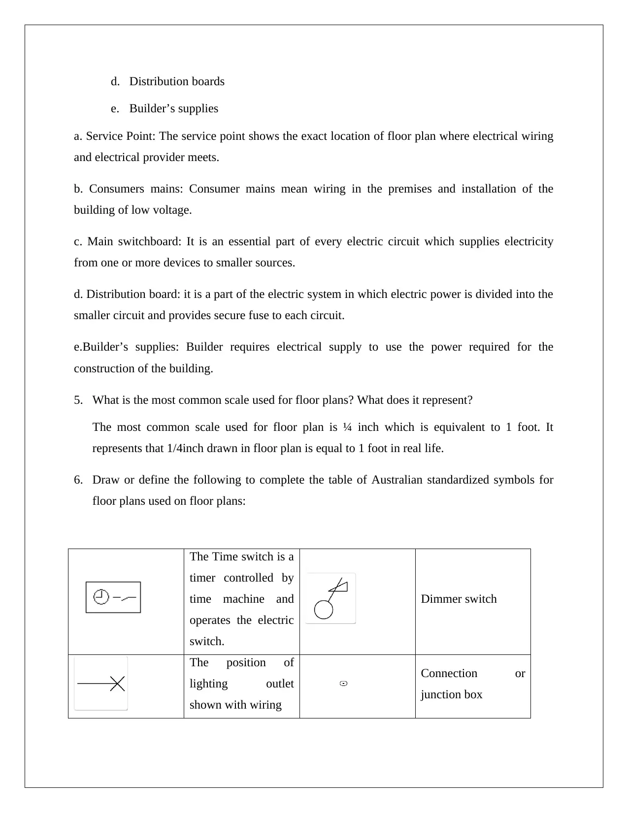
6. Draw or define the following to complete the table of Australian standardized symbols for
floor plans used on floor plans:
The Time switch is a
timer controlled by
time machine and
operates the electric
switch.
Dimmer switch
The position of
lighting outlet
shown with wiring
Connection or
junction box
e. Builder’s supplies
a. Service Point: The service point shows the exact location of floor plan where electrical wiring
and electrical provider meets.
b. Consumers mains: Consumer mains mean wiring in the premises and installation of the
building of low voltage.
c. Main switchboard: It is an essential part of every electric circuit which supplies electricity
from one or more devices to smaller sources.
d. Distribution board: it is a part of the electric system in which electric power is divided into the
smaller circuit and provides secure fuse to each circuit.
e.Builder’s supplies: Builder requires electrical supply to use the power required for the
construction of the building.
5. What is the most common scale used for floor plans? What does it represent?
The most common scale used for floor plan is ¼ inch which is equivalent to 1 foot. It
represents that 1/4inch drawn in floor plan is equal to 1 foot in real life.
6. Draw or define the following to complete the table of Australian standardized symbols for
floor plans used on floor plans:
The Time switch is a
timer controlled by
time machine and
operates the electric
switch.
Dimmer switch
The position of
lighting outlet
shown with wiring
Connection or
junction box
Paraphrase This Document
Need a fresh take? Get an instant paraphrase of this document with our AI Paraphraser
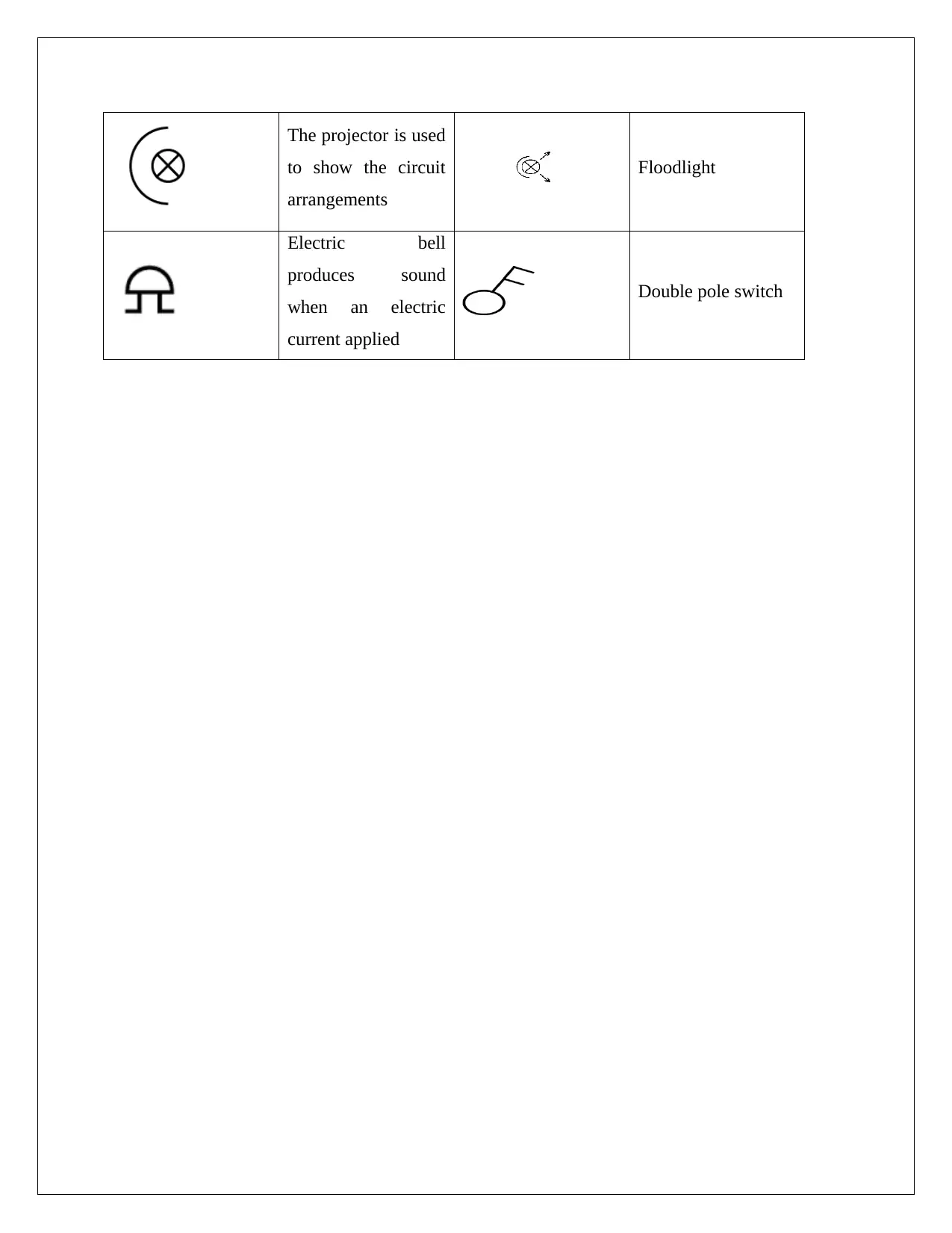
The projector is used
to show the circuit
arrangements
Floodlight
Electric bell
produces sound
when an electric
current applied
Double pole switch
to show the circuit
arrangements
Floodlight
Electric bell
produces sound
when an electric
current applied
Double pole switch
Task 2 - Electrical drawings
1. Describe the purpose of each of the following types of electrical drawings:
a. Block diagrams
b. Circuit diagrams
c. Wiring diagrams
d. Ladder diagrams
a) Block Diagrams: Block Diagrams are used in electronic design to show the relationship
between blocks by connecting them to lines.
b) Circuit Diagrams: A circuit diagram also called the electrical diagram is used to graphically
show the electric circuit.
c) Wiring Diagrams: Wiring diagram is a symbolic illustration of an electric circuit.
d) Ladder Diagrams: In ladder diagrams, functions of the control circuit are represented.
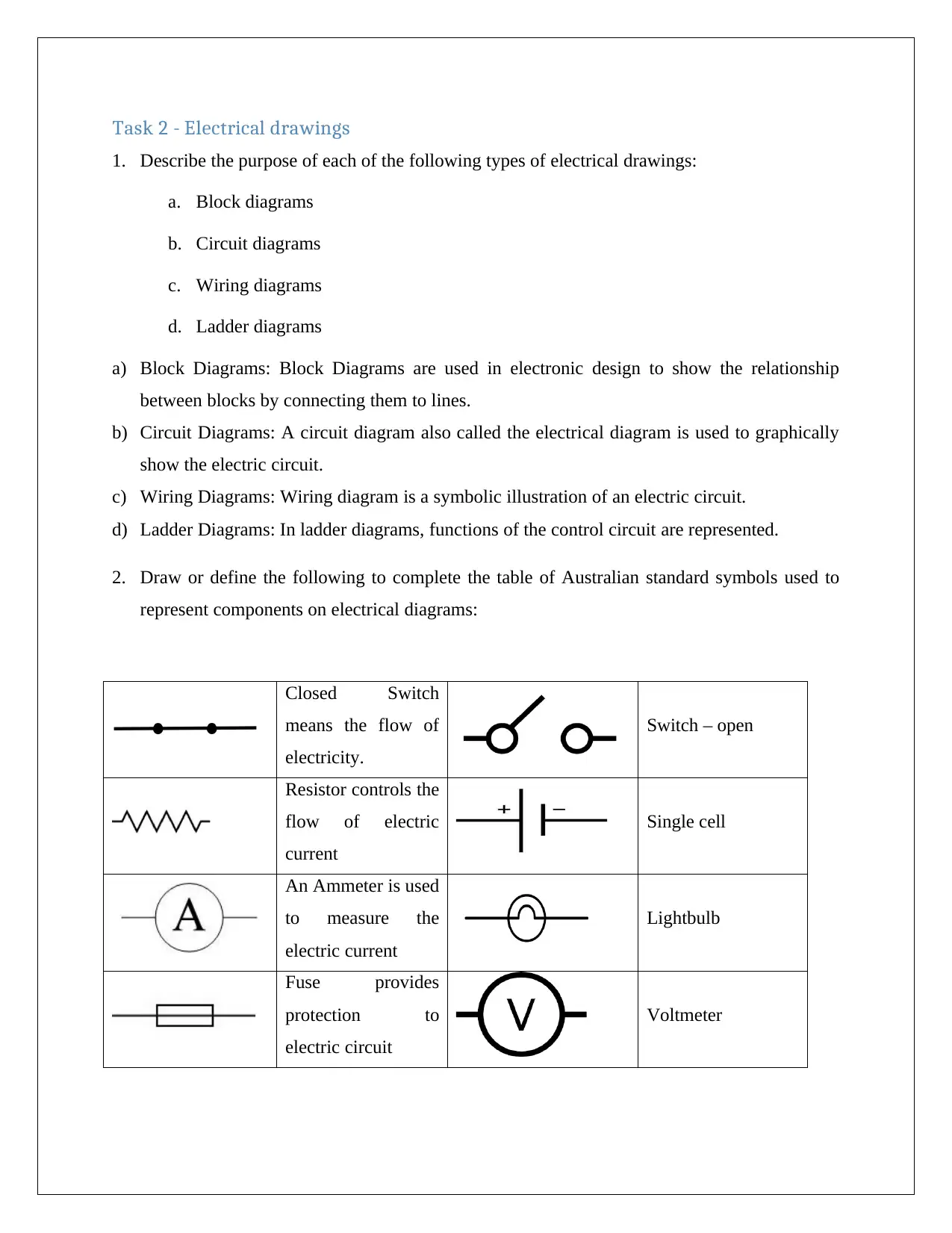
2. Draw or define the following to complete the table of Australian standard symbols used to
represent components on electrical diagrams:
Closed Switch
means the flow of
electricity.
Switch – open
Resistor controls the
flow of electric
current
Single cell
An Ammeter is used
to measure the
electric current
Lightbulb
Fuse provides
protection to
electric circuit
Voltmeter
1. Describe the purpose of each of the following types of electrical drawings:
a. Block diagrams
b. Circuit diagrams
c. Wiring diagrams
d. Ladder diagrams
a) Block Diagrams: Block Diagrams are used in electronic design to show the relationship
between blocks by connecting them to lines.
b) Circuit Diagrams: A circuit diagram also called the electrical diagram is used to graphically
show the electric circuit.
c) Wiring Diagrams: Wiring diagram is a symbolic illustration of an electric circuit.
d) Ladder Diagrams: In ladder diagrams, functions of the control circuit are represented.
2. Draw or define the following to complete the table of Australian standard symbols used to
represent components on electrical diagrams:
Closed Switch
means the flow of
electricity.
Switch – open
Resistor controls the
flow of electric
current
Single cell
An Ammeter is used
to measure the
electric current
Lightbulb
Fuse provides
protection to
electric circuit
Voltmeter
⊘ This is a preview!⊘
Do you want full access?
Subscribe today to unlock all pages.
Trusted by 1+ million students worldwide
3. What are the conventions and used in and the features of circuit diagrams?
To make sure that all workers are using the diagram the incorrect way, standard circuit
diagrams are used with standard symbols. The main components used in circuit diagram
includes Protection devices, Conductors, Device controls, capacitors, diodes, resistors,
inductors, load, transistors, power source, and ground. Circuit diagram includes two main
features: one is that all connections must be in order and second is that all components should
use standard symbols.
4. What is required to convert a circuit diagram to a wiring diagram?
To convert a circuit diagram into wiring diagram, it is necessary to make sure that wiring
diagram must have all the required information and for this, check all connection
requirements, switches required for connection and terminal connections
5. What is a cable schedule?
To complete the installation of specific circuit or wiring task, cable schedule is required that
contains all necessary cables. It can be designed to determine the approximate length,
resources, and materials required for the diagram.
6. What information will be listed on the cable schedule regarding each of the cables included?
The following information is listed on the cable schedule:
Size of each cable
Cable number
Complete detail of resource, endpoint and destination of cable
Each cable’s length
dimensions necessary for each cable
what type of cable is required
7. What steps are involved in developing a cable schedule for a given installation?
Following steps requires in budding a cable plan for given installation:
For each connection, check all requirements of cables.
Paraphrase This Document
Need a fresh take? Get an instant paraphrase of this document with our AI Paraphraser

Check all cable routes and access points required to develop a cable schedule.
Record all cables
Find appropriate specifications for each cable
Make an easy and readable table that includes all information mentioned in above
steps.
Record all cables
Find appropriate specifications for each cable
Make an easy and readable table that includes all information mentioned in above
steps.
Task 3 - Circuit diagrams
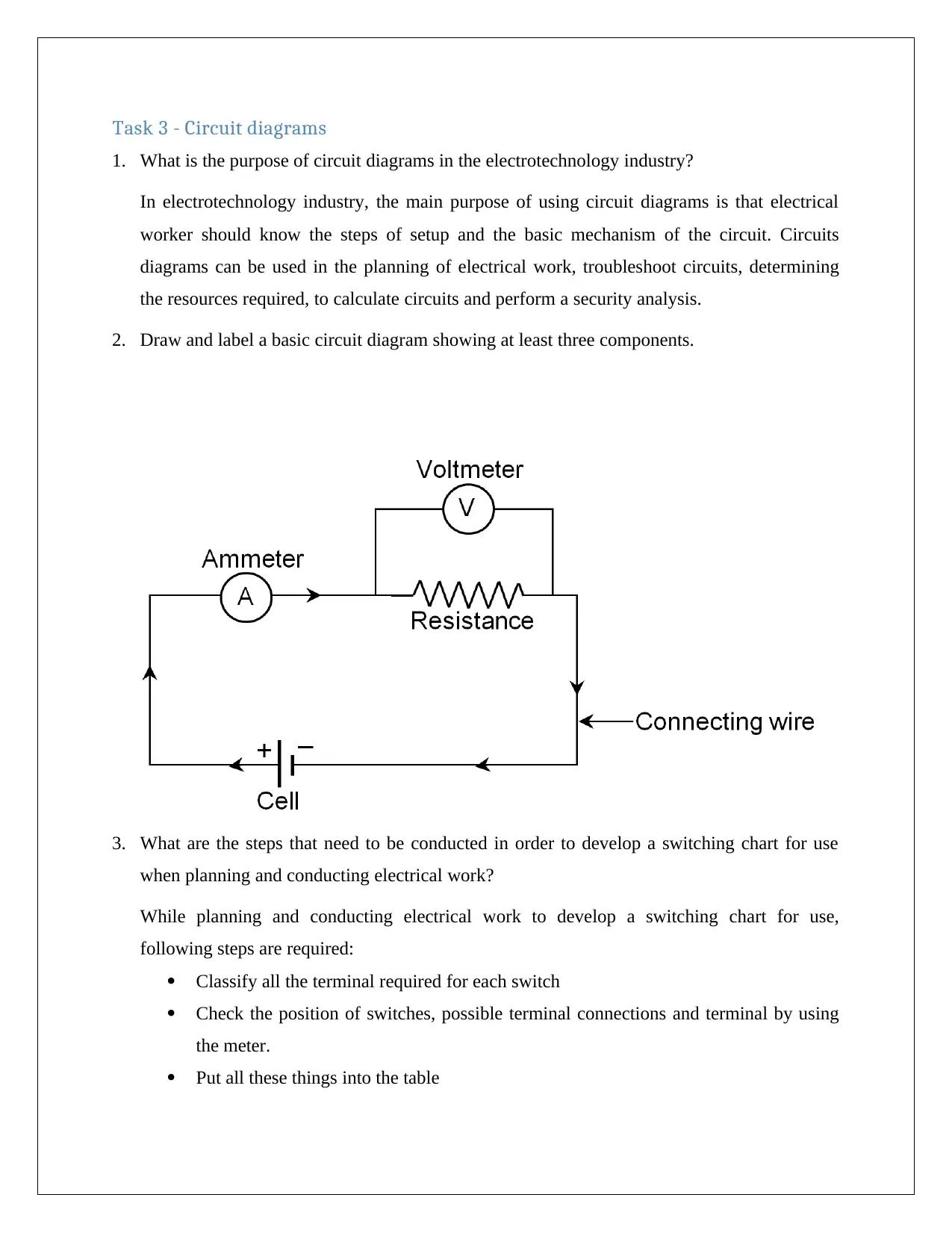
1. What is the purpose of circuit diagrams in the electrotechnology industry?
In electrotechnology industry, the main purpose of using circuit diagrams is that electrical
worker should know the steps of setup and the basic mechanism of the circuit. Circuits
diagrams can be used in the planning of electrical work, troubleshoot circuits, determining
the resources required, to calculate circuits and perform a security analysis.
2. Draw and label a basic circuit diagram showing at least three components.
3. What are the steps that need to be conducted in order to develop a switching chart for use
when planning and conducting electrical work?
While planning and conducting electrical work to develop a switching chart for use,
following steps are required:
Classify all the terminal required for each switch
Check the position of switches, possible terminal connections and terminal by using
the meter.
Put all these things into the table
⊘ This is a preview!⊘
Do you want full access?
Subscribe today to unlock all pages.
Trusted by 1+ million students worldwide

4. What needs to be kept in mind when preparing to connect equipment using circuit diagrams?
While preparing to connect equipment using circuit diagrams, all information must be
consulted and calculations made in connecting equipment must also be performed to make
sure that all terminal connections and details will not show when circuit requirements linked
with circuit diagrams.
While preparing to connect equipment using circuit diagrams, all information must be
consulted and calculations made in connecting equipment must also be performed to make
sure that all terminal connections and details will not show when circuit requirements linked
with circuit diagrams.
Paraphrase This Document
Need a fresh take? Get an instant paraphrase of this document with our AI Paraphraser
Task 4 - Wiring diagrams
1. What is the purpose of wiring diagrams in the electrotechnology industry?
Wiring diagrams can be used to represent the planning of system wiring, house wiring,
device wiring and lighting plans. Its main purpose is to show the symbolic representation of
complete circuit or complete installation of the electrical circuit.
2. What conventions are used in wiring diagrams?
A wiring diagram provides the information on arrangements and positions of devices and end
point of devices. Standard symbols are used in standard wiring diagrams to show the
electrical components. Conventions used in wiring diagrams include resistor, capacitor,
inductors and relays.
3. What are the features of wiring diagrams?
Features of wiring diagrams are:
Connections of terminals
Basic symbols required to connect in circuit
The relationship between devices and connections
Structure of the wiring circuit
4. What can sketch basic wiring assist with?
Some workers draw the basic sketch of the wiring diagram to understand the symbolic
representation of an electrical plan. Sketching the basic wiring diagrams can be very simple
and basic and assist in making plans and development of wiring systems and in
troubleshooting also. Also, sketching of basic wiring diagrams should be drawn with
standard electrical symbols.
5. Draw or define the following to complete the table of Australian standard symbols used in
wiring diagrams
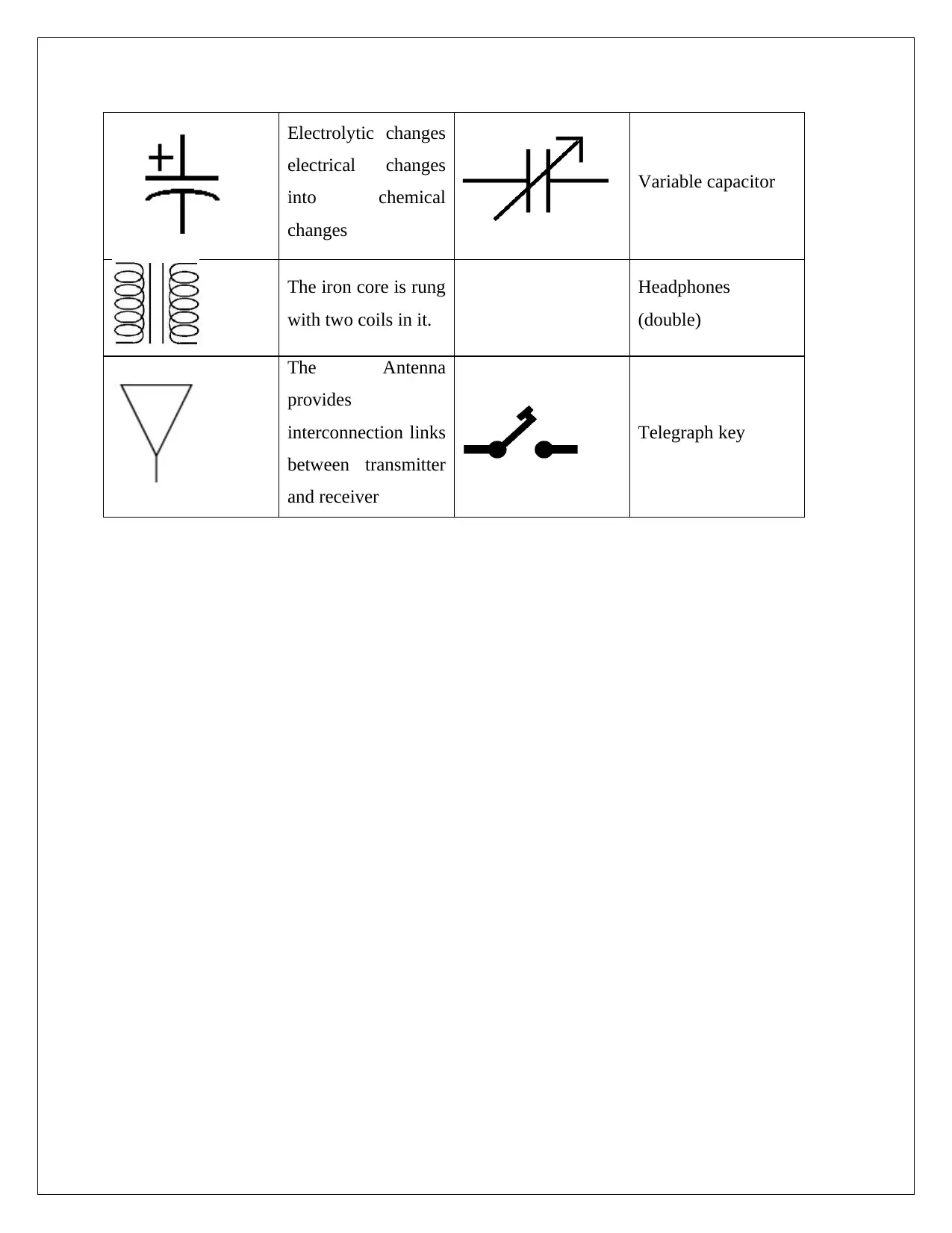
Electrolytic changes
electrical changes
into chemical
changes
Variable capacitor
The iron core is rung
with two coils in it.
Headphones
(double)
The Antenna
provides
interconnection links
between transmitter
and receiver
Telegraph key
electrical changes
into chemical
changes
Variable capacitor
The iron core is rung
with two coils in it.
Headphones
(double)
The Antenna
provides
interconnection links
between transmitter
and receiver
Telegraph key
⊘ This is a preview!⊘
Do you want full access?
Subscribe today to unlock all pages.
Trusted by 1+ million students worldwide
1 out of 28
Related Documents


Your All-in-One AI-Powered Toolkit for Academic Success.
+13062052269
info@desklib.com
Available 24*7 on WhatsApp / Email
![[object Object]](/_next/static/media/star-bottom.7253800d.svg)
Unlock your academic potential
Copyright © 2020–2025 A2Z Services. All Rights Reserved. Developed and managed by ZUCOL.