SC4107 - Research Methodology: Ultrasonic Signal Processing for NDE
VerifiedAdded on 2023/05/28
|16
|3050
|373
Report
AI Summary
This report delves into the application of ultrasonic signal processing for industrial non-destructive evaluation (NDE). It addresses the challenges of detecting echoes in ultrasonic NDE, emphasizing the importance of backscattered echoes for information on defect orientation, boundaries, and sizes. The report outlines the background of ultrasound inspection, focusing on pulse-echo techniques and the impact of noise on measurement accuracy. It details the system description, including data acquisition and positioning subsystems, highlighting the use of FPGA-based systems and components like touchscreen boards, ADC/DAC boards, and Microblaze processors. The implementation process, utilizing C and VHDL languages with Xilinx ISE suite, is also discussed, along with specifications of the FPGA, DAC, and ADC boards. The report further covers the touch-screen subsystem and signal processing on FPGA, including split spectrum processing. It concludes with a project plan outlining key activities and timelines.
RESEARCH METHODOLOGY:
ULTRASONIC SIGNAL PROCESSING FOR INDUSTRIAL NON-DESTRUCTIVE
EVALUATION
Name of Student
Subject Name
Date
ULTRASONIC SIGNAL PROCESSING FOR INDUSTRIAL NON-DESTRUCTIVE
EVALUATION
Name of Student
Subject Name
Date
Paraphrase This Document
Need a fresh take? Get an instant paraphrase of this document with our AI Paraphraser
Introduction
The concept of the ultrasonic non-destructive assessment essentially applied in the failure
analysis as well as quality assessment. The application has vital application in various industries
such as bridge structures, microelectronic, manufacturing, aircraft structures as well as
packaging. Preferably, it is important that ultrasonic NDE faces the challenge of been detected
with the echoes. The recorded echoes tend to be random as well as interfere with the makeable
elements and can even be contaminated by the overall noise. Therefore, there are various
challenges in recording the backscattered echoes in the process. Conversely, the importance of
recording the backscattered echoes cannot be underestimated since they have desired
information. Some of the key information associated with the process include orientation,
boundaries as well as defect sizes. Furthermore, the analogy of the ultrasonic processes often
manifested in material characterization as well as in the overall structural health monitoring. In
recent days, developers have come up with different designs and modifications for the algorithm
signal processes (Iyer, Sinha, Tittmann and Pedrick 2012 p.135). The design includes both the
nonlinear and the non-stationary ultrasonic signals behavior in line with the NDE application.
Furthermore, there has been extensive research on different aspects in line with the ultrasonic
signal processing. Some of the vital areas mainly discussed in the processes include chirplet
signal decomposition, empirical mode decomposition, Hilbert-huang transform, Fractional
Fourier transforms as well as active noise cancellation. Other than the benefits of developing
algorithms in signal processing of ultrasonic in the industrial applications, there are also different
problems which one is likely to encounter in the process. The key challenge is on the
implementation bit of the algorithms in the hardware concept. Preferably, there is vast
understanding that NDE requires numerous and in-depth fieldworks for one to be able to
understand the NDR operators nature. Notably, ultrasonic processes have got wide range of
applications and these often have immense advantages in long run.
Background
Ultrasound inspection has paramount application in the detection of the elementary and internal
discontinuities in various substances. The application is vital and it is applied for both
components and equipment. There is wide application the pulse-echo and this is grounded on the
fact that the application is simple. Preferably, pulse-echo test tend to have one transducer in the
system. This is used for receiving as well as sending the ultrasonic waves. Also, the pulse-echo is
used for checking for the dimensions as well as for verifying for the parametric location. Noise
is an essential factor which one must consider in conducting the ultrasonic testing. The factor is
an essential ingredient which not only affects the accuracy but also the reliability of
measurements recorded. This is considered in both the acoustic and electronic devices. The
element plays an essential role in dealing with computational intelligence as well as digital signal
processing (Zhang, Yang and Fan 2010 p.529).
Aims and Objectives
This thesis research aims at exploring the non-destructive evaluation using the concept of the
ultrasonic signals as well as processing. Furthermore, the study also incorporates the utilization
of the transforms and the signal features in the appraisal concept. In essence, this study mainly
conducted in line with the yield detection and techniques. There is the application of the linear
discriminant analysis or LDA which is referred for the study and the concept regards the overall
performance of various classifiers mainly compared and examined in the process (Manjula,
Vijayarekha and Venkatraman 2018 p.264).
Methodology
System Description
⊘ This is a preview!⊘
Do you want full access?
Subscribe today to unlock all pages.
Trusted by 1+ million students worldwide
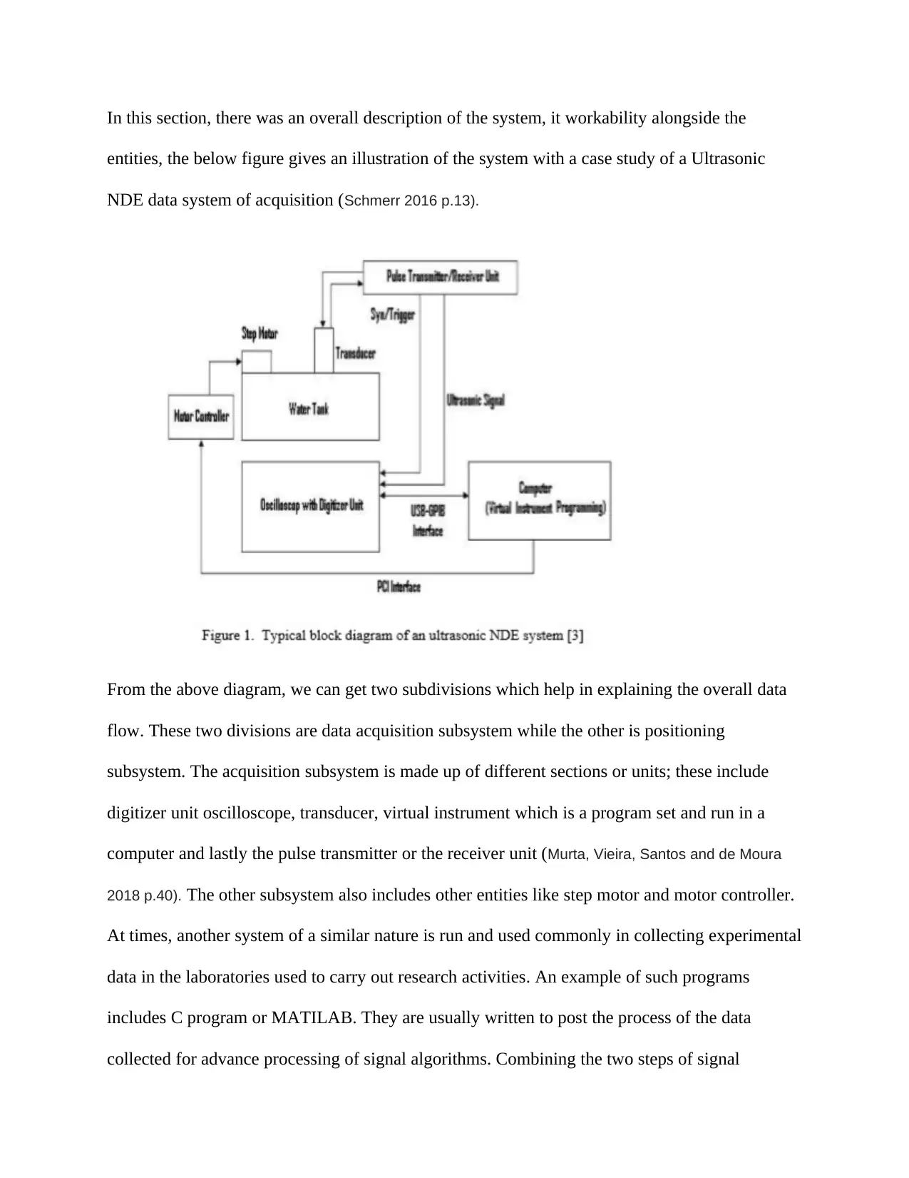
In this section, there was an overall description of the system, it workability alongside the
entities, the below figure gives an illustration of the system with a case study of a Ultrasonic
NDE data system of acquisition (Schmerr 2016 p.13).
From the above diagram, we can get two subdivisions which help in explaining the overall data
flow. These two divisions are data acquisition subsystem while the other is positioning
subsystem. The acquisition subsystem is made up of different sections or units; these include
digitizer unit oscilloscope, transducer, virtual instrument which is a program set and run in a
computer and lastly the pulse transmitter or the receiver unit (Murta, Vieira, Santos and de Moura
2018 p.40). The other subsystem also includes other entities like step motor and motor controller.
At times, another system of a similar nature is run and used commonly in collecting experimental
data in the laboratories used to carry out research activities. An example of such programs
includes C program or MATILAB. They are usually written to post the process of the data
collected for advance processing of signal algorithms. Combining the two steps of signal
Paraphrase This Document
Need a fresh take? Get an instant paraphrase of this document with our AI Paraphraser
processing and data acquisition always pose a major challenge thus to curb this; a specified
system algorithm is designed carefully for use.
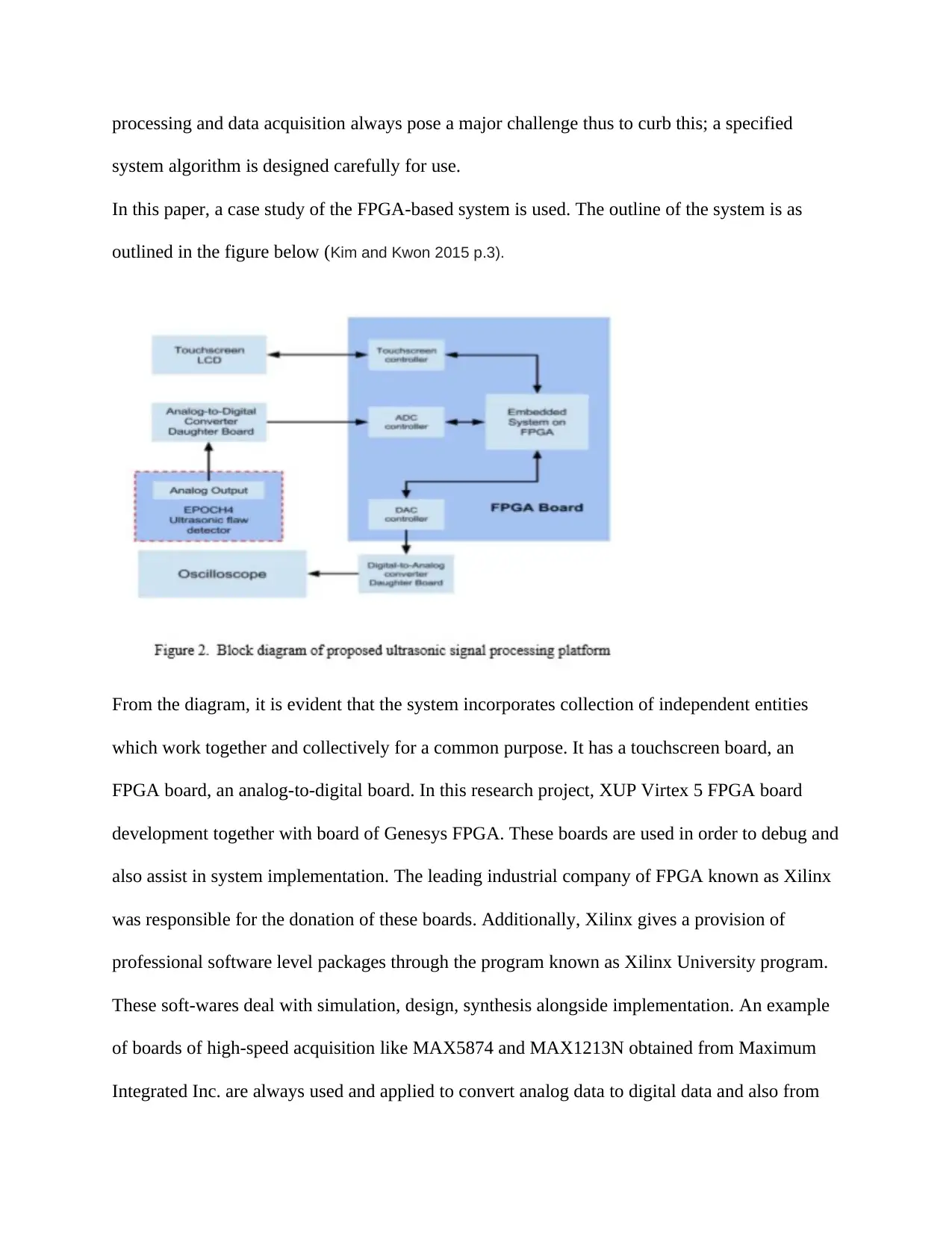
In this paper, a case study of the FPGA-based system is used. The outline of the system is as
outlined in the figure below (Kim and Kwon 2015 p.3).
From the diagram, it is evident that the system incorporates collection of independent entities
which work together and collectively for a common purpose. It has a touchscreen board, an
FPGA board, an analog-to-digital board. In this research project, XUP Virtex 5 FPGA board
development together with board of Genesys FPGA. These boards are used in order to debug and
also assist in system implementation. The leading industrial company of FPGA known as Xilinx
was responsible for the donation of these boards. Additionally, Xilinx gives a provision of
professional software level packages through the program known as Xilinx University program.
These soft-wares deal with simulation, design, synthesis alongside implementation. An example
of boards of high-speed acquisition like MAX5874 and MAX1213N obtained from Maximum
Integrated Inc. are always used and applied to convert analog data to digital data and also from
system algorithm is designed carefully for use.
In this paper, a case study of the FPGA-based system is used. The outline of the system is as
outlined in the figure below (Kim and Kwon 2015 p.3).
From the diagram, it is evident that the system incorporates collection of independent entities
which work together and collectively for a common purpose. It has a touchscreen board, an
FPGA board, an analog-to-digital board. In this research project, XUP Virtex 5 FPGA board
development together with board of Genesys FPGA. These boards are used in order to debug and
also assist in system implementation. The leading industrial company of FPGA known as Xilinx
was responsible for the donation of these boards. Additionally, Xilinx gives a provision of
professional software level packages through the program known as Xilinx University program.
These soft-wares deal with simulation, design, synthesis alongside implementation. An example
of boards of high-speed acquisition like MAX5874 and MAX1213N obtained from Maximum
Integrated Inc. are always used and applied to convert analog data to digital data and also from
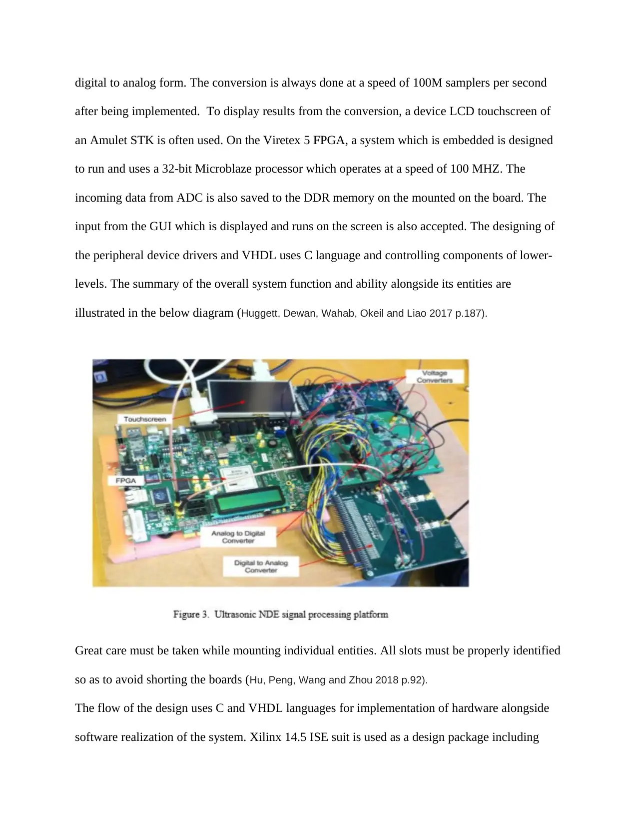
digital to analog form. The conversion is always done at a speed of 100M samplers per second
after being implemented. To display results from the conversion, a device LCD touchscreen of
an Amulet STK is often used. On the Viretex 5 FPGA, a system which is embedded is designed
to run and uses a 32-bit Microblaze processor which operates at a speed of 100 MHZ. The
incoming data from ADC is also saved to the DDR memory on the mounted on the board. The
input from the GUI which is displayed and runs on the screen is also accepted. The designing of
the peripheral device drivers and VHDL uses C language and controlling components of lower-
levels. The summary of the overall system function and ability alongside its entities are
illustrated in the below diagram (Huggett, Dewan, Wahab, Okeil and Liao 2017 p.187).
Great care must be taken while mounting individual entities. All slots must be properly identified
so as to avoid shorting the boards (Hu, Peng, Wang and Zhou 2018 p.92).
The flow of the design uses C and VHDL languages for implementation of hardware alongside
software realization of the system. Xilinx 14.5 ISE suit is used as a design package including
⊘ This is a preview!⊘
Do you want full access?
Subscribe today to unlock all pages.
Trusted by 1+ million students worldwide
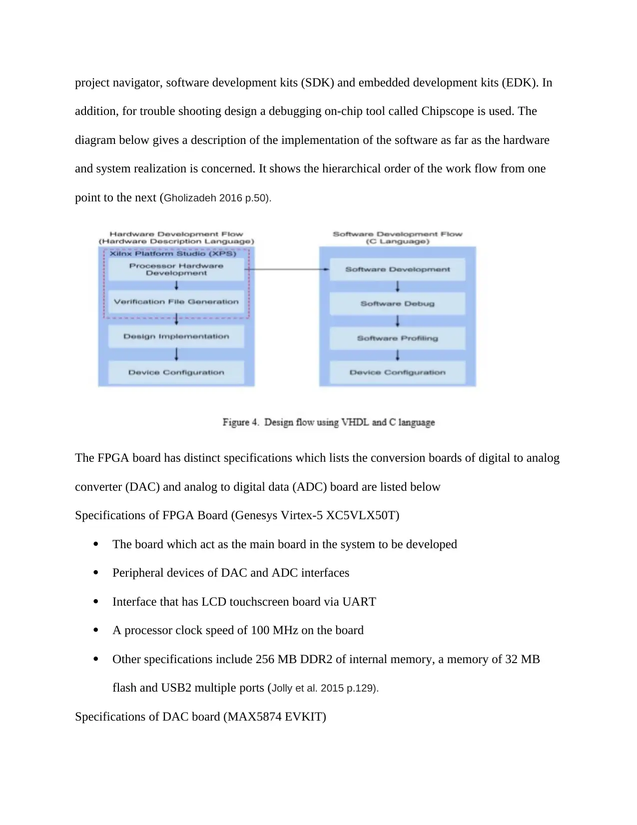
project navigator, software development kits (SDK) and embedded development kits (EDK). In
addition, for trouble shooting design a debugging on-chip tool called Chipscope is used. The
diagram below gives a description of the implementation of the software as far as the hardware
and system realization is concerned. It shows the hierarchical order of the work flow from one
point to the next (Gholizadeh 2016 p.50).
The FPGA board has distinct specifications which lists the conversion boards of digital to analog
converter (DAC) and analog to digital data (ADC) board are listed below
Specifications of FPGA Board (Genesys Virtex-5 XC5VLX50T)
The board which act as the main board in the system to be developed
Peripheral devices of DAC and ADC interfaces
Interface that has LCD touchscreen board via UART
A processor clock speed of 100 MHz on the board
Other specifications include 256 MB DDR2 of internal memory, a memory of 32 MB
flash and USB2 multiple ports (Jolly et al. 2015 p.129).
Specifications of DAC board (MAX5874 EVKIT)
Paraphrase This Document
Need a fresh take? Get an instant paraphrase of this document with our AI Paraphraser
MAX5874: A 14-bit, performance of a high-dynamic on DAC obtained from Maxim
Integrated, Inc.
A 200 M samples per second updates supporter.
An operation of below 3.3V and 1.8V supplies provided by the FPGA board and a
MAX1536 voltage converter.
A 100 MHz clock signal controller from the FPGA board.
A single-ended output analog signal between 0 and 2Vpp
Specifications of ADC board (MAX1213N EVKIT)
MAX1213N: 12-bit low power ADC obtained from Maxim Integrated, Inc.
Sampling rate supporter of up to a speed of 170 M samples per second.
Operation rate of less than 3.3V and 1.8V supplies which is provided by the FPGA board
alongside a MAX1536 voltage converter.
Controlled by a processor clocks peed of 100 MHz signal from the FPGA board.
Analog input signal acceptor of single end occurring between 0 and 2Vpp (EPOCH 4
analog signal source provided by ultrasonic flaw detector)
Output signal of 12 differential LVDS2.5
In the course of the research study, there are some key elements which are vital to the
connections and general input layout. The daughter boards must be well connected in order to
give a proper signal coordination. The main board links all of them together with FPGA and
collectively the signals are transmitted. Much time is taken in finding connection faults. Some of
the observations generated from this are:
The analog ground and the digital ground are to be separated for the better control of the noise
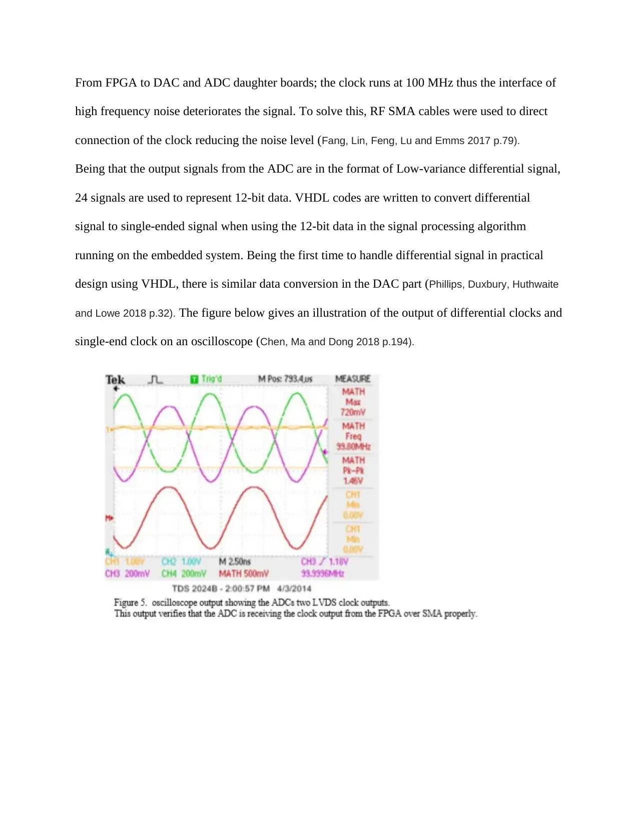
From FPGA to DAC and ADC daughter boards; the clock runs at 100 MHz thus the interface of
high frequency noise deteriorates the signal. To solve this, RF SMA cables were used to direct
connection of the clock reducing the noise level (Fang, Lin, Feng, Lu and Emms 2017 p.79).
Being that the output signals from the ADC are in the format of Low-variance differential signal,
24 signals are used to represent 12-bit data. VHDL codes are written to convert differential
signal to single-ended signal when using the 12-bit data in the signal processing algorithm
running on the embedded system. Being the first time to handle differential signal in practical
design using VHDL, there is similar data conversion in the DAC part (Phillips, Duxbury, Huthwaite
and Lowe 2018 p.32). The figure below gives an illustration of the output of differential clocks and
single-end clock on an oscilloscope (Chen, Ma and Dong 2018 p.194).
⊘ This is a preview!⊘
Do you want full access?
Subscribe today to unlock all pages.
Trusted by 1+ million students worldwide
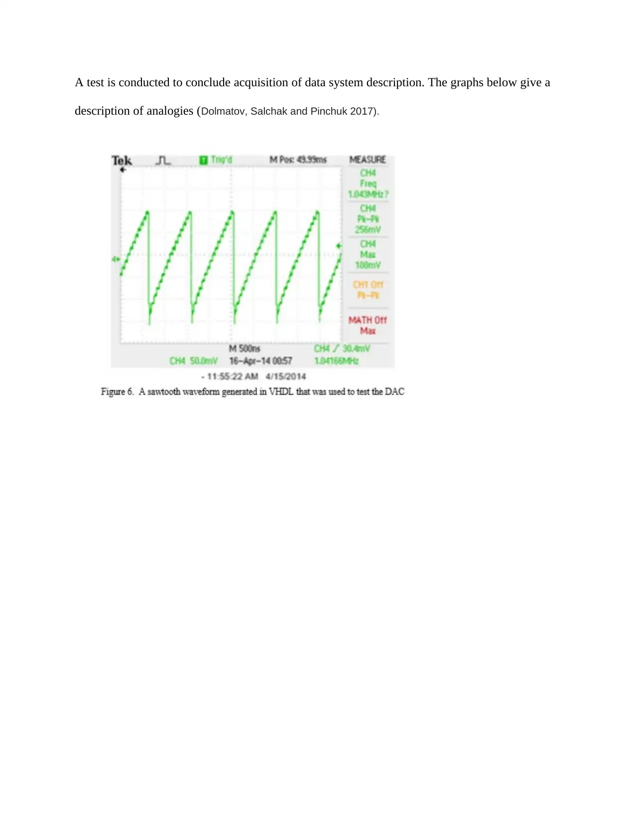
A test is conducted to conclude acquisition of data system description. The graphs below give a
description of analogies (Dolmatov, Salchak and Pinchuk 2017).
description of analogies (Dolmatov, Salchak and Pinchuk 2017).
Paraphrase This Document
Need a fresh take? Get an instant paraphrase of this document with our AI Paraphraser
Touch-screen subsystem
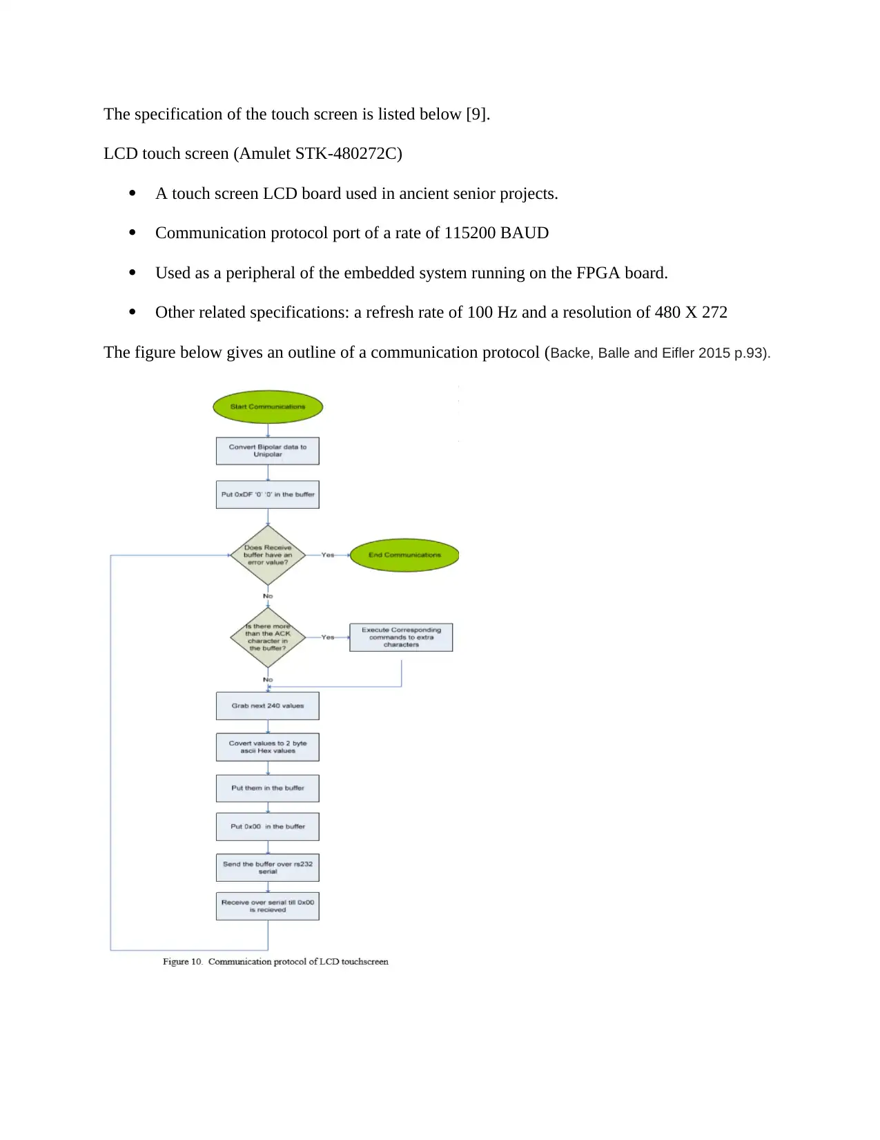
The specification of the touch screen is listed below [9].
LCD touch screen (Amulet STK-480272C)
A touch screen LCD board used in ancient senior projects.
Communication protocol port of a rate of 115200 BAUD
Used as a peripheral of the embedded system running on the FPGA board.
Other related specifications: a refresh rate of 100 Hz and a resolution of 480 X 272
The figure below gives an outline of a communication protocol (Backe, Balle and Eifler 2015 p.93).
⊘ This is a preview!⊘
Do you want full access?
Subscribe today to unlock all pages.
Trusted by 1+ million students worldwide
1 out of 16

Your All-in-One AI-Powered Toolkit for Academic Success.
+13062052269
info@desklib.com
Available 24*7 on WhatsApp / Email
![[object Object]](/_next/static/media/star-bottom.7253800d.svg)
Unlock your academic potential
Copyright © 2020–2026 A2Z Services. All Rights Reserved. Developed and managed by ZUCOL.