UML Diagram & Case Diagram: Mobile Application System Design Project

Verified

Added on  2023/02/01

|22
|1705
|98
Project
AI Summary
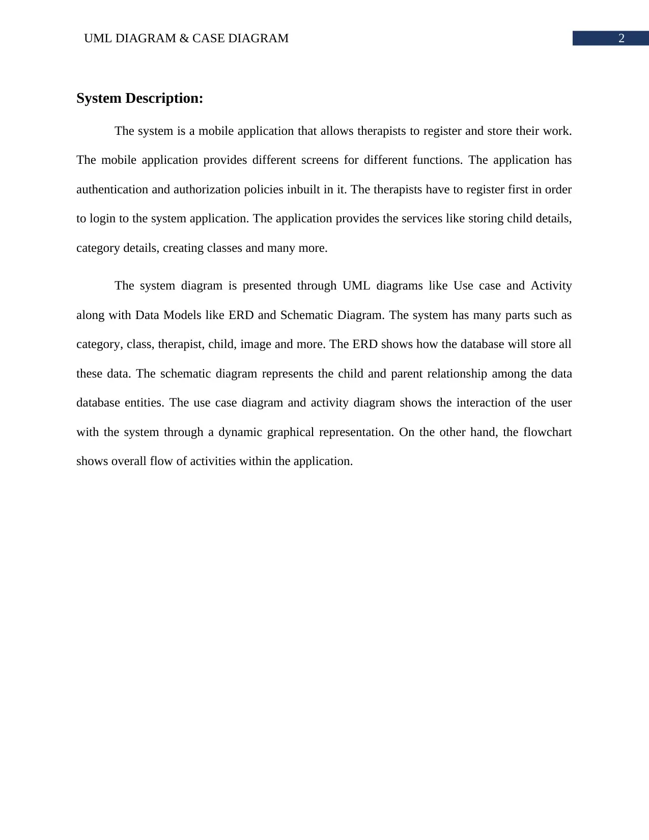
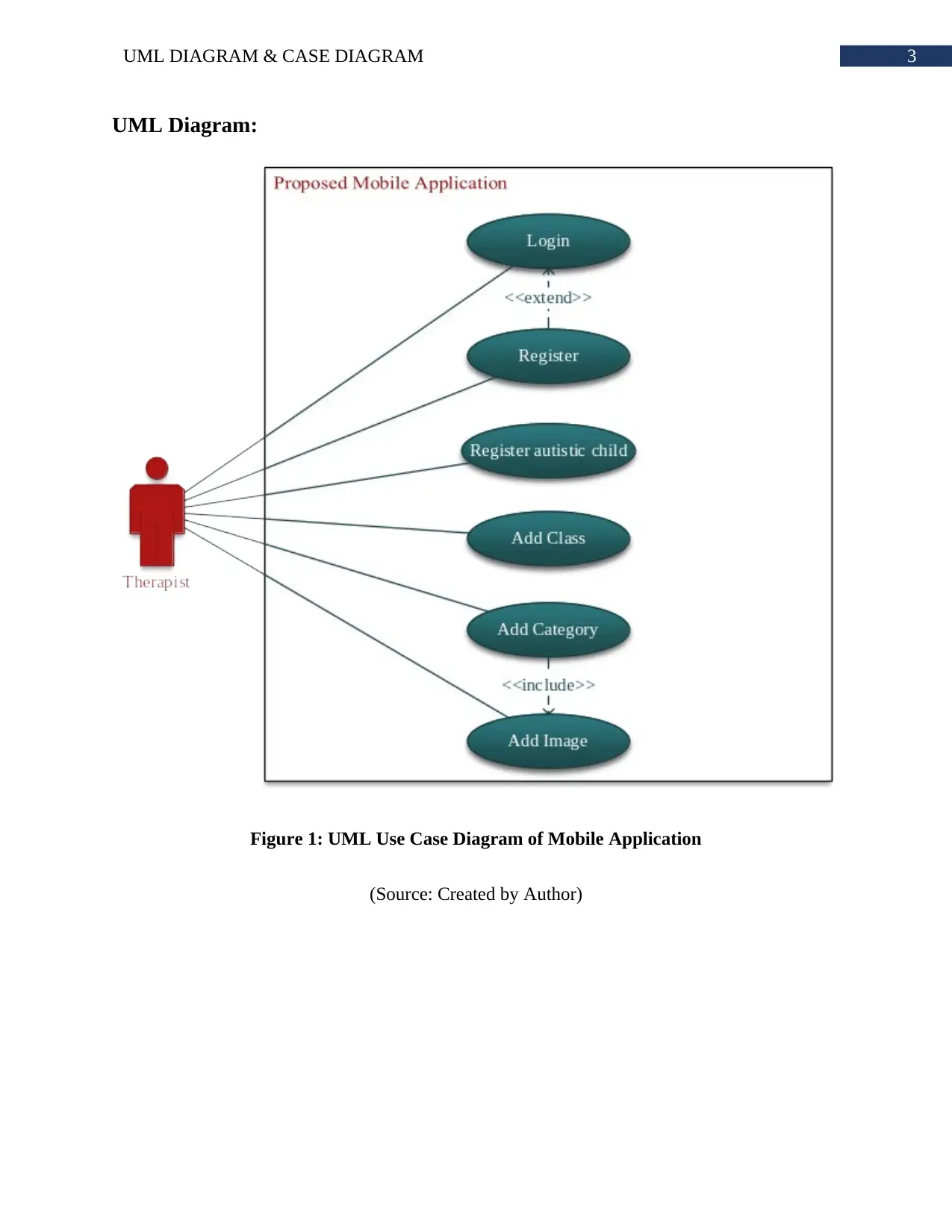
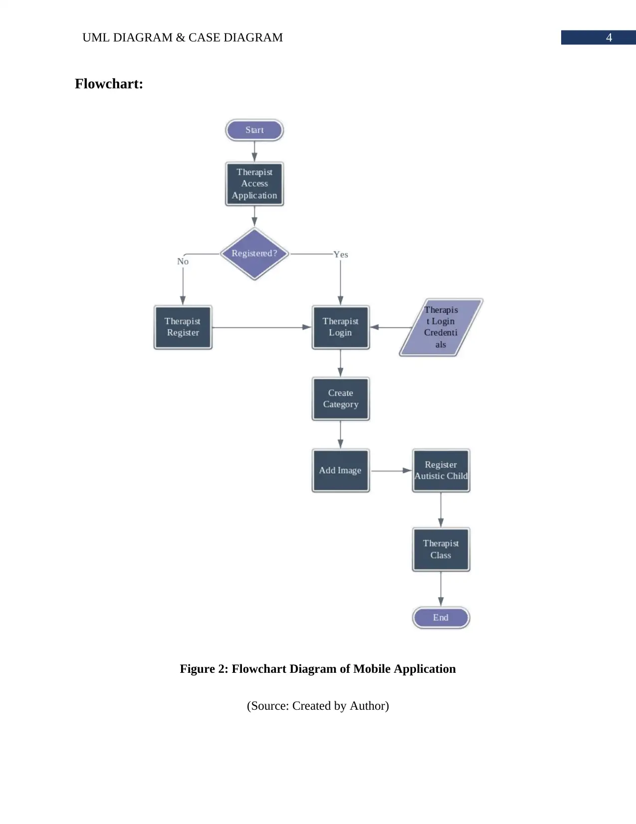
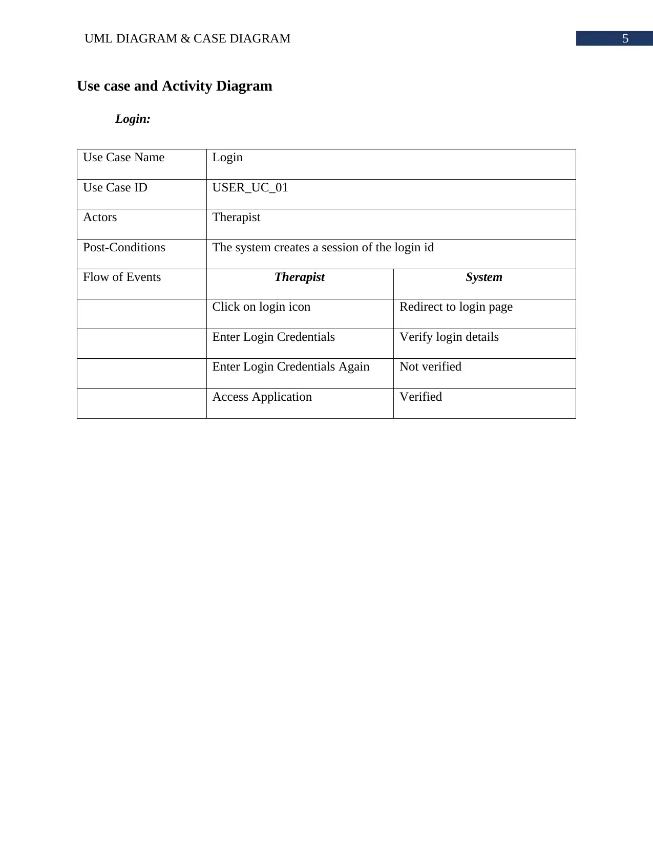
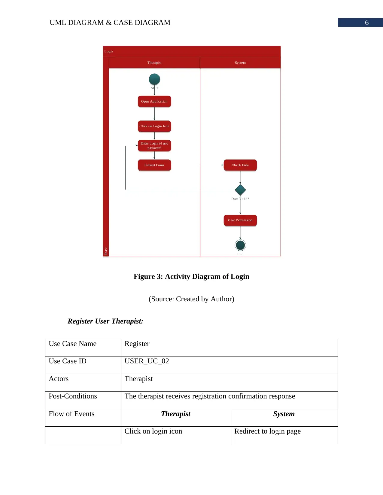
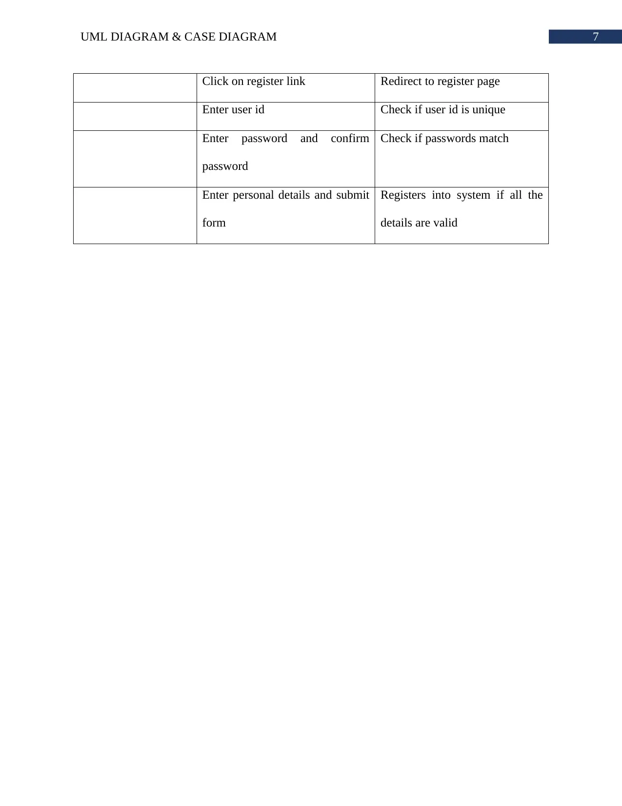
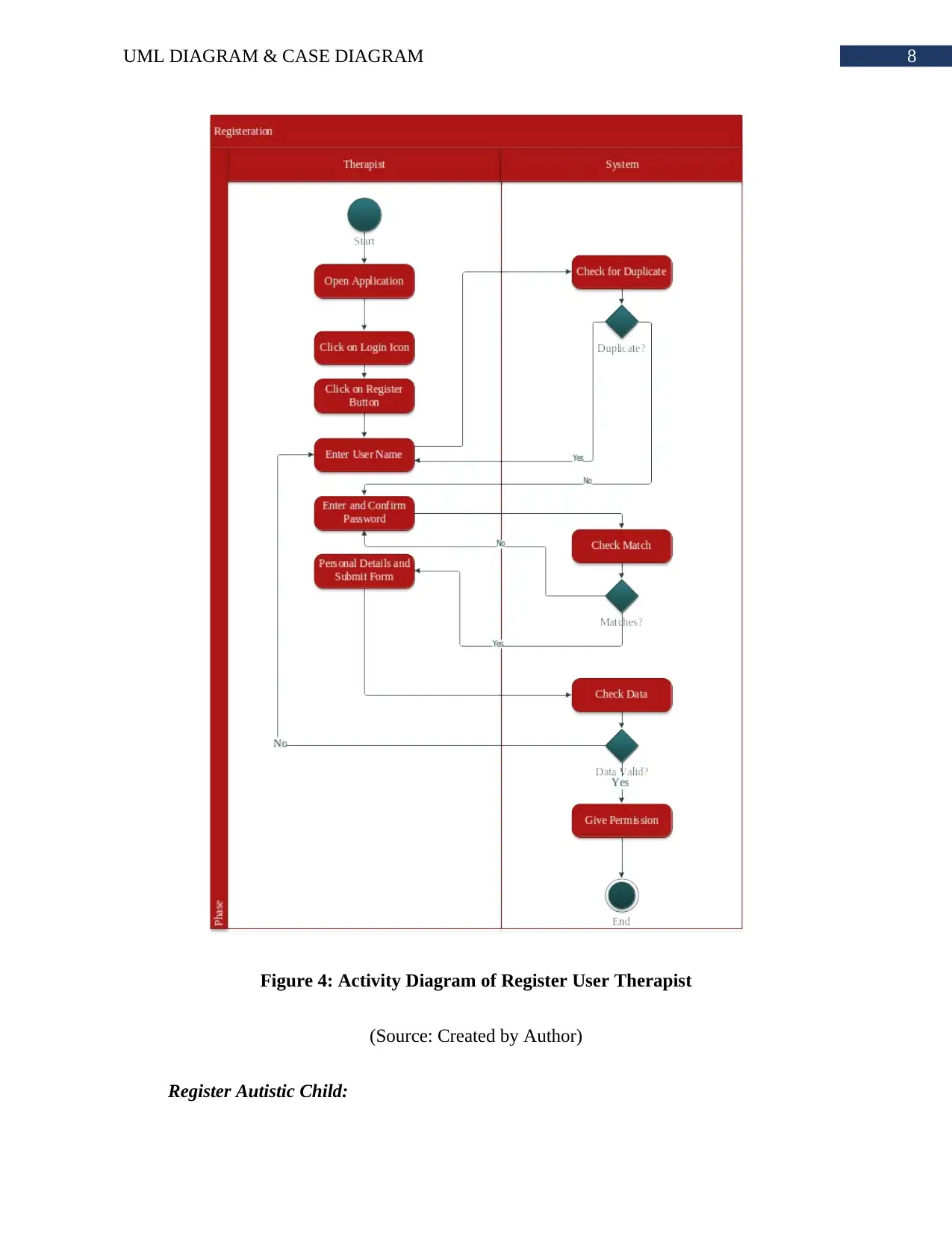
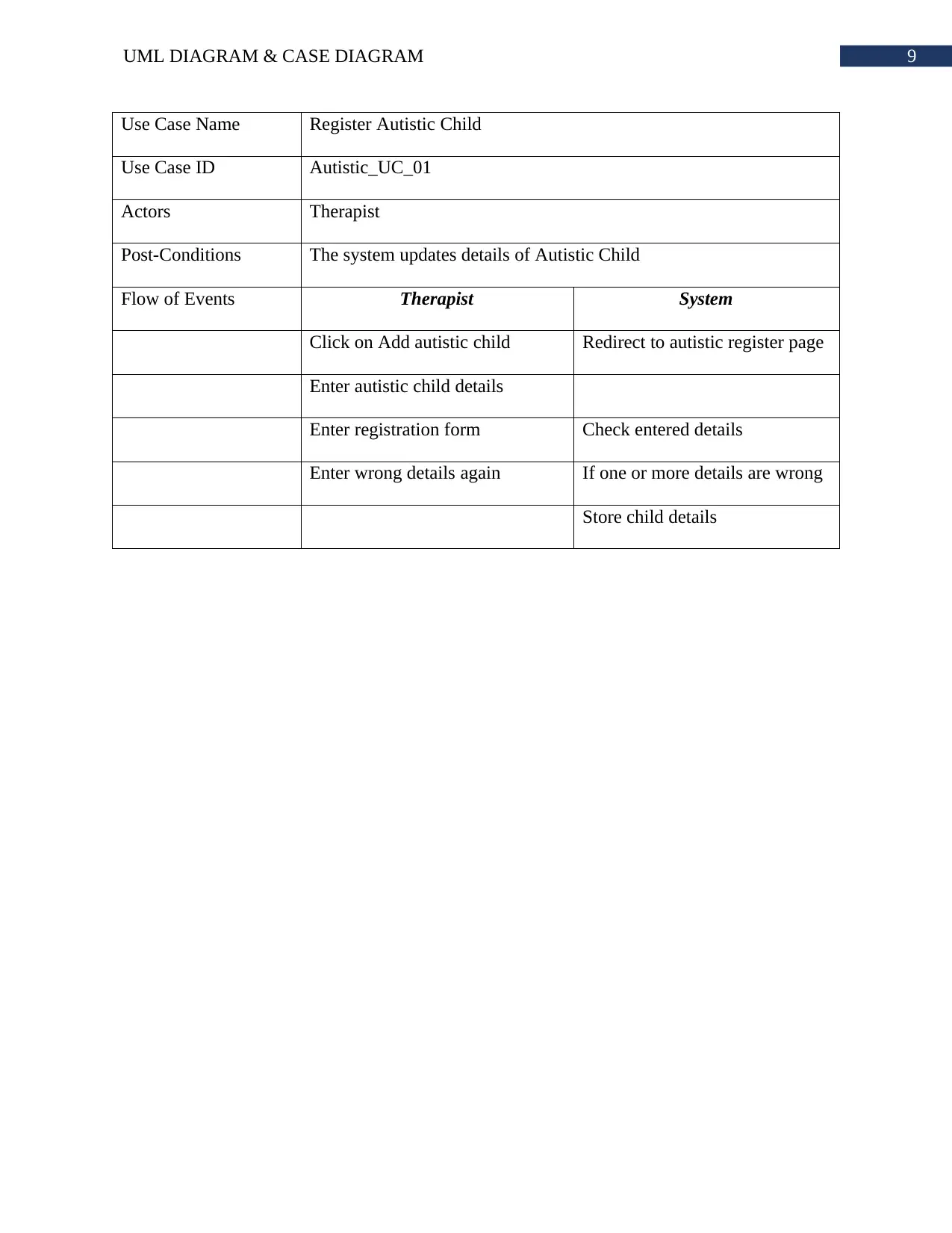
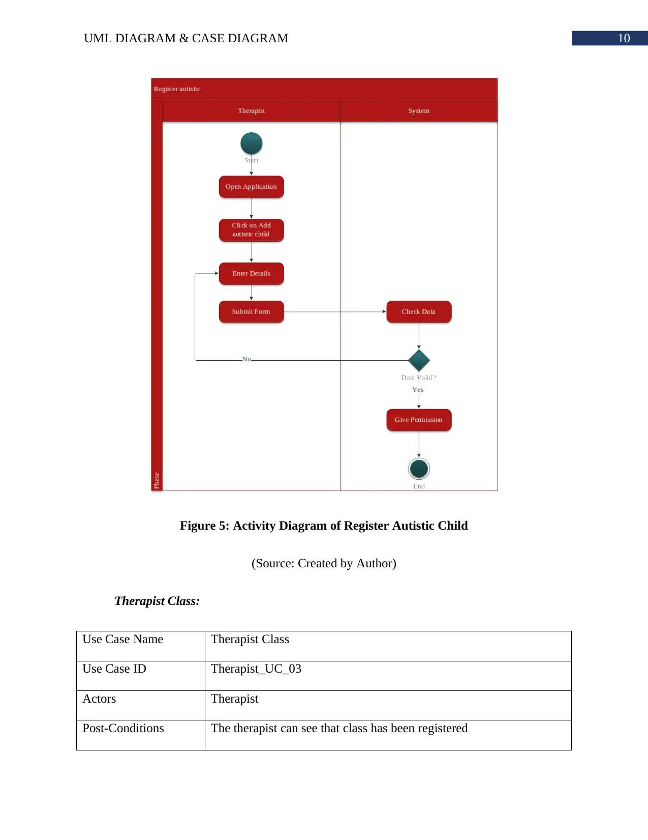
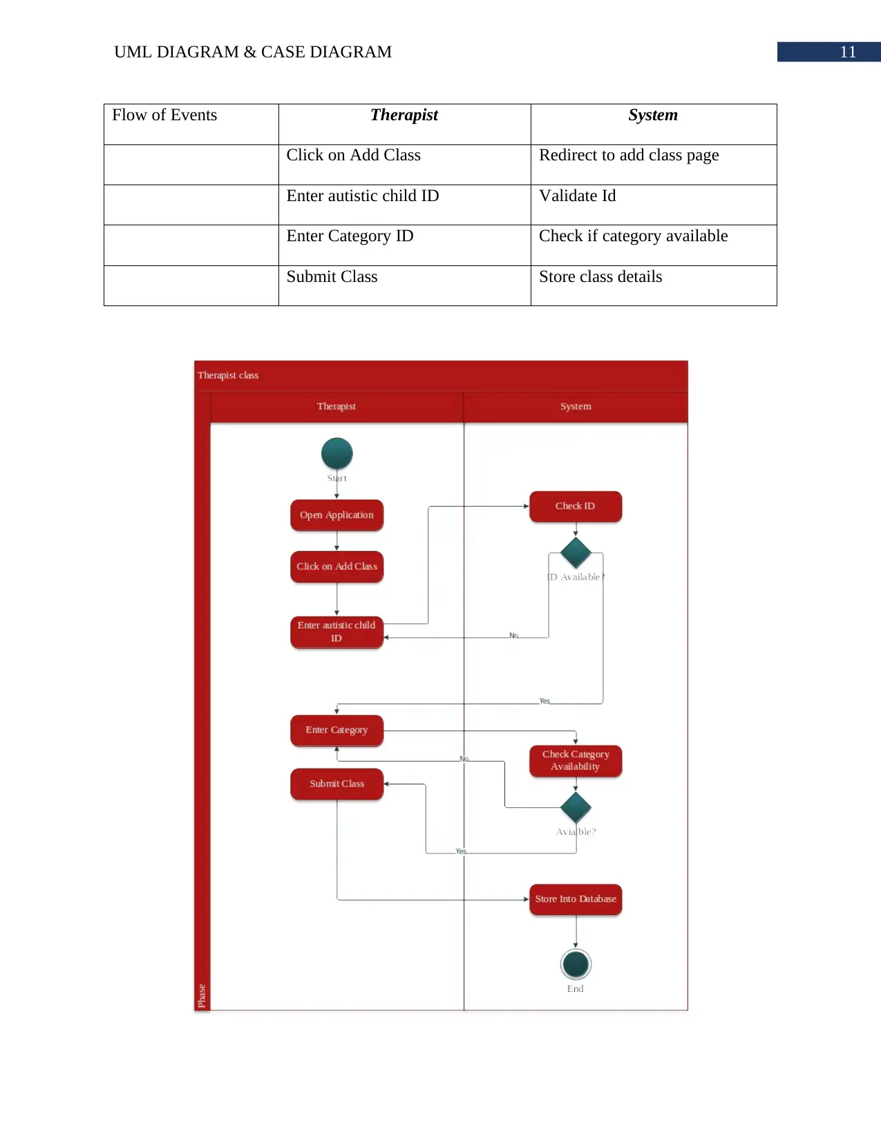
This project provides a comprehensive system design for a mobile application, employing a variety of UML diagrams to illustrate different aspects of the system. The project begins with a system description, outlining the application's functionality, which allows therapists to register and manage their work. It then presents a use case diagram depicting the interactions between the therapist and the system. Following this, the project includes a flowchart that visualizes the overall flow of activities within the application. The core of the project consists of detailed use case and activity diagrams for key functionalities like login, user registration, registering autistic children, creating therapist classes, adding categories, and adding images. The project also covers database design, including normalization to ensure data integrity, an entity-relationship diagram (ERD) to represent the database structure, and a schematic diagram that illustrates the relationships between database entities. The project also includes a bibliography of relevant resources.
tabler-icon-diamond-filled.svg

Contribute Materials

Your contribution can guide someone’s learning journey. Share your documents today.
Document Page
Running head: UML DIAGRAM & CASE DIAGRAM
UML Diagram & Case Diagram
Name of the Student
Name of the University
Author’s note:
tabler-icon-diamond-filled.svg

Secure Best Marks with AI Grader

Need help grading? Try our AI Grader for instant feedback on your assignments.
Document Page
1UML DIAGRAM & CASE DIAGRAM
Table of Contents
System Description:.........................................................................................................................2
UML Diagram:................................................................................................................................3
Flowchart:........................................................................................................................................4
Use case and Activity Diagram.......................................................................................................5
Normalization:...............................................................................................................................15
Entity Relationship Diagram:........................................................................................................18
Schematic Diagram:.......................................................................................................................19
Bibliography:.................................................................................................................................20
Document Page
2UML DIAGRAM & CASE DIAGRAM
System Description:
The system is a mobile application that allows therapists to register and store their work.
The mobile application provides different screens for different functions. The application has
authentication and authorization policies inbuilt in it. The therapists have to register first in order
to login to the system application. The application provides the services like storing child details,
category details, creating classes and many more.
The system diagram is presented through UML diagrams like Use case and Activity
along with Data Models like ERD and Schematic Diagram. The system has many parts such as
category, class, therapist, child, image and more. The ERD shows how the database will store all
these data. The schematic diagram represents the child and parent relationship among the data
database entities. The use case diagram and activity diagram shows the interaction of the user
with the system through a dynamic graphical representation. On the other hand, the flowchart
shows overall flow of activities within the application.
Document Page
3UML DIAGRAM & CASE DIAGRAM
UML Diagram:
Figure 1: UML Use Case Diagram of Mobile Application
(Source: Created by Author)
tabler-icon-diamond-filled.svg

Secure Best Marks with AI Grader

Need help grading? Try our AI Grader for instant feedback on your assignments.
Document Page
4UML DIAGRAM & CASE DIAGRAM
Flowchart:
Figure 2: Flowchart Diagram of Mobile Application
(Source: Created by Author)
Document Page
5UML DIAGRAM & CASE DIAGRAM
Use case and Activity Diagram
Login:
Use Case Name Login
Use Case ID USER_UC_01
Actors Therapist
Post-Conditions The system creates a session of the login id
Flow of Events Therapist System
Click on login icon Redirect to login page
Enter Login Credentials Verify login details
Enter Login Credentials Again Not verified
Access Application Verified
Document Page
6UML DIAGRAM & CASE DIAGRAM
Figure 3: Activity Diagram of Login
(Source: Created by Author)
Register User Therapist:
Use Case Name Register
Use Case ID USER_UC_02
Actors Therapist
Post-Conditions The therapist receives registration confirmation response
Flow of Events Therapist System
Click on login icon Redirect to login page
tabler-icon-diamond-filled.svg

Paraphrase This Document

Need a fresh take? Get an instant paraphrase of this document with our AI Paraphraser
Document Page
7UML DIAGRAM & CASE DIAGRAM
Click on register link Redirect to register page
Enter user id Check if user id is unique
Enter password and confirm
password
Check if passwords match
Enter personal details and submit
form
Registers into system if all the
details are valid
Document Page
8UML DIAGRAM & CASE DIAGRAM
Figure 4: Activity Diagram of Register User Therapist
(Source: Created by Author)
Register Autistic Child:
Document Page
9UML DIAGRAM & CASE DIAGRAM
Use Case Name Register Autistic Child
Use Case ID Autistic_UC_01
Actors Therapist
Post-Conditions The system updates details of Autistic Child
Flow of Events Therapist System
Click on Add autistic child Redirect to autistic register page
Enter autistic child details
Enter registration form Check entered details
Enter wrong details again If one or more details are wrong
Store child details
tabler-icon-diamond-filled.svg

Secure Best Marks with AI Grader

Need help grading? Try our AI Grader for instant feedback on your assignments.
Document Page
10UML DIAGRAM & CASE DIAGRAM
Figure 5: Activity Diagram of Register Autistic Child
(Source: Created by Author)
Therapist Class:
Use Case Name Therapist Class
Use Case ID Therapist_UC_03
Actors Therapist
Post-Conditions The therapist can see that class has been registered
Document Page
11UML DIAGRAM & CASE DIAGRAM
Flow of Events Therapist System
Click on Add Class Redirect to add class page
Enter autistic child ID Validate Id
Enter Category ID Check if category available
Submit Class Store class details
Document Page
12UML DIAGRAM & CASE DIAGRAM
Figure 6: Activity Diagram of Register Autistic Child
(Source: Created by Author)
Add Category:
Use Case Name Add Category
Use Case ID Therapist_UC_04
Actors Therapist
Post-Conditions A new category is added to be linked to class
Flow of Events Therapist System
Click on Add Category Show category registration form
Enter Category Details Check format of input data
Submit Form Store category into system
tabler-icon-diamond-filled.svg

Paraphrase This Document

Need a fresh take? Get an instant paraphrase of this document with our AI Paraphraser
Document Page
13UML DIAGRAM & CASE DIAGRAM
Figure 7: Activity Diagram of Add Category
(Source: Created by Author)
Add Image:
Use Case Name Add Image
Use Case ID Therapist_UC_04_Sub_01
Actors Therapist
Post-Conditions An icon will be linked with category
Document Page
14UML DIAGRAM & CASE DIAGRAM
Flow of Events Therapist System
Add Category Category added and system asks
to add image to category
Click on Add Image Show upload image option
Re-upload image Image not supported
Image stored and linked with
category
Document Page
15UML DIAGRAM & CASE DIAGRAM
Figure 8: Activity Diagram of Add Image
(Source: Created by Author)
Normalization:
Therapist_id Class_id Child_id Categiry_id Image_id
1 101 201 301 401
tabler-icon-diamond-filled.svg

Secure Best Marks with AI Grader

Need help grading? Try our AI Grader for instant feedback on your assignments.
Document Page
16UML DIAGRAM & CASE DIAGRAM
102 202 302 402
2 103 201 301 401
The above table shows that there are multivalued attributes. In order to make the table in
first normal form, the multivalued attributes needs to be converted into atomic attribute. The
table will look like below in first normal form.
Therapist_id Class_id Child_id Categiry_id Image_id
1 101 201 301 401
1 102 202 302 402
2 103 201 301 401
As per the description of the system, there will be only one icon per category. Therefore,
the images are associated with the category. In order to make the tables in second normal form,
each partial dependency needs to be removed. Therefore, after removing the partial dependency
of image_id on category_id, there will be three tables.
Therapist_id Class_id Child_id Categiry_id
1 101 201 301
1 102 202 302
2 103 201 301
Categiry_id Image_id
301 401
Document Page
17UML DIAGRAM & CASE DIAGRAM
302 402
Image_id Description
401 A
402 B
The third normal form removes transitive dependency from the database tables. If all the
transitive dependencies are removed then therapist, child and category will have a different table.
These tables will be connected to each other by having foreign key in the Class table. Therefore,
total number of tables in the database will be five.
Class_id Therapist_id Child_id Categiry_id Class_description
101 1 201 301 A
102 1 202 302 V
103 2 201 301 D
Child_id Name
201 A
202 B
Therapist_id Therapist_name
1 A
Document Page
18UML DIAGRAM & CASE DIAGRAM
2 C
Categiry_id Image_id name
301 401 A
302 402 B
Image_id Description
401 A
402 B
Entity Relationship Diagram:
tabler-icon-diamond-filled.svg

Paraphrase This Document

Need a fresh take? Get an instant paraphrase of this document with our AI Paraphraser
Document Page
19UML DIAGRAM & CASE DIAGRAM
Figure 9: Entity Relationship Diagram of Proposed Mobile Application
(Source: Created by Author)
Schematic Diagram:
Figure 10: Schematic Diagram of Proposed Mobile Application Database
(Source: Created by Author)
Document Page
20UML DIAGRAM & CASE DIAGRAM
Bibliography:
Al-Masree, H.K., 2015. Extracting Entity Relationship Diagram (ERD) from relational database
schema. International Journal of Database Theory and Application, 8(3), pp.15-26.
Arora, P.K. and Bhatia, R., 2018. Agent-Based Regression Test Case Generation using Class
Diagram, Use cases and Activity Diagram. Procedia Computer Science, 125, pp.747-753.
Carrion, D., Migliaccio, F., Minini, G. and Zambrano, C., 2016. From historical documents to
GIS: A spatial database for medieval fiscal data in Southern Italy. Historical Methods: A Journal
of Quantitative and Interdisciplinary History, 49(1), pp.1-10.
Dick, J., Hull, E. and Jackson, K., 2017. Requirements engineering. Springer.
Felderer, M. and Herrmann, A., 2018. Comprehensibility of system models during test design: a
controlled experiment comparing UML activity diagrams and state machines. Software Quality
Journal, pp.1-23.
Jagtap, S., Gawde, V., Pawar, R., Shendge, S. and Avhad, P., 2016. Generate Test Cases From
UML Use Case and State Chart Diagrams. International Research Journal of Engineering and
Technology (IRJET), 3, pp.873-881.
Karim, S., Liawatimena, S., Trisetyarso, A., Abbas, B.S. and Suparta, W., 2017, November.
Automating functional and structural software size measurement based on XML structure of
UML sequence diagram. In 2017 IEEE International Conference on Cybernetics and
Computational Intelligence (CyberneticsCom) (pp. 24-28). IEEE.
Document Page
21UML DIAGRAM & CASE DIAGRAM
Khurana, N., Chhillar, R.S. and Chhillar, U., 2016. A Novel Technique for Generation and
Optimization of Test Cases Using Use Case, Sequence, Activity Diagram and Genetic
Algorithm. JSW, 11(3), pp.242-250.
Kruse, S.L.K. and Wells, M.G., 2016. Optionality of ERD Relationships: Project for the
Introduction to Database Course. In Proceedings of the EDSIG Conference ISSN (Vol. 2473, p.
3857).
Kumar, B. and Singh, K., 2015. Testing uml designs using class, sequence and activity
diagrams. International Journal for Innovative Research in Science and Technology, 2(3), pp.71-
81.
Mai, P.X., Goknil, A., Shar, L.K., Pastore, F., Briand, L.C. and Shaame, S., 2018. Modeling
security and privacy requirements: a use case-driven approach. Information and Software
Technology, 100, pp.165-182.
Nassif, A.B., Capretz, L.F. and Ho, D., 2016. Enhancing use case points estimation method using
soft computing techniques. arXiv preprint arXiv:1612.01078.
Zhang, F., Ma, Z.M. and Cheng, J., 2016. Enhanced entity-relationship modeling with
description logic. Knowledge-Based Systems, 93, pp.12-32.
chevron_up_icon
1 out of 22
circle_padding
hide_on_mobile
zoom_out_icon
logo.png

Your All-in-One AI-Powered Toolkit for Academic Success.

Available 24*7 on WhatsApp / Email

[object Object]