IMAT5205 Systems Analysis: The Role of UML in Project Lifecycles

Verified

Added on  2023/05/30

|10
|1930
|137
Essay
AI Summary
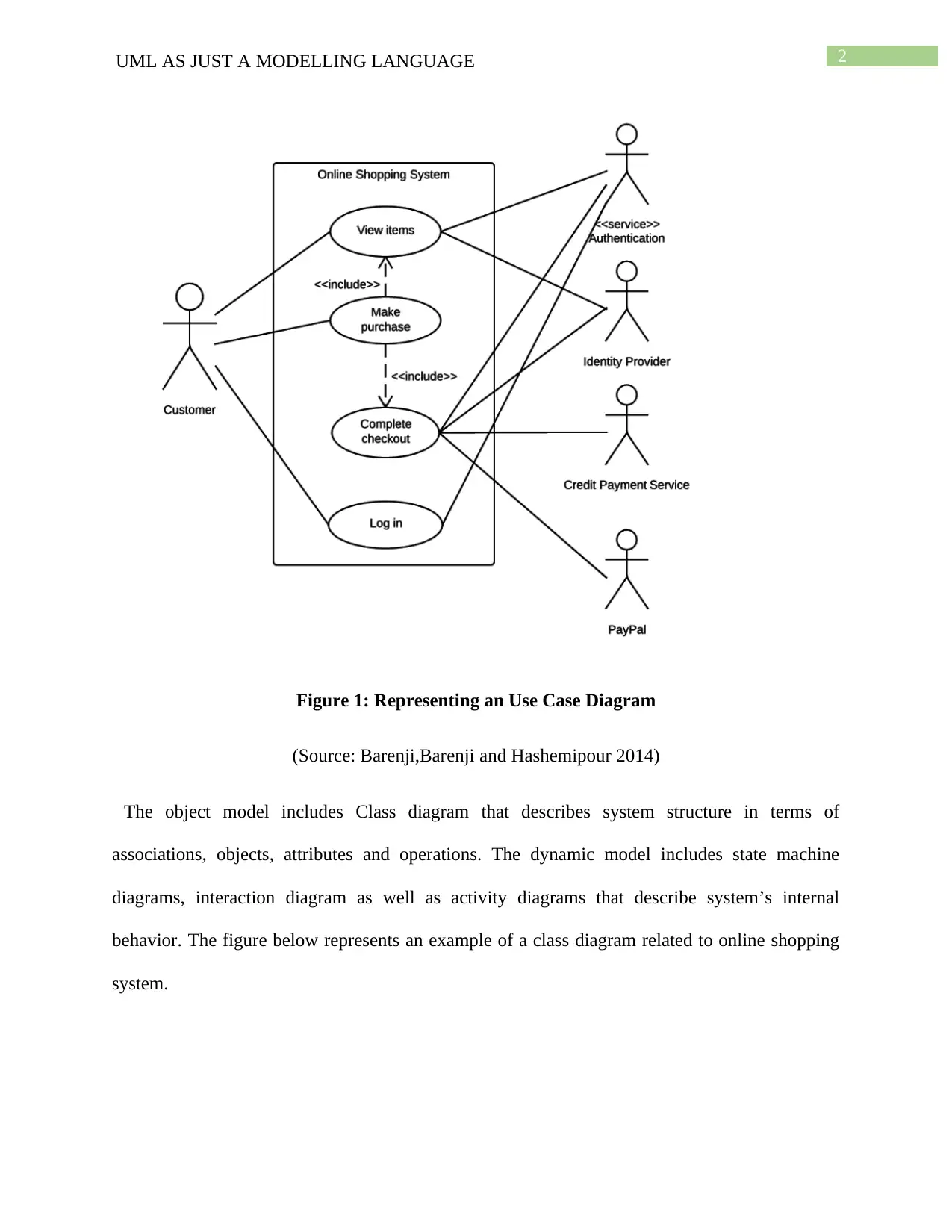
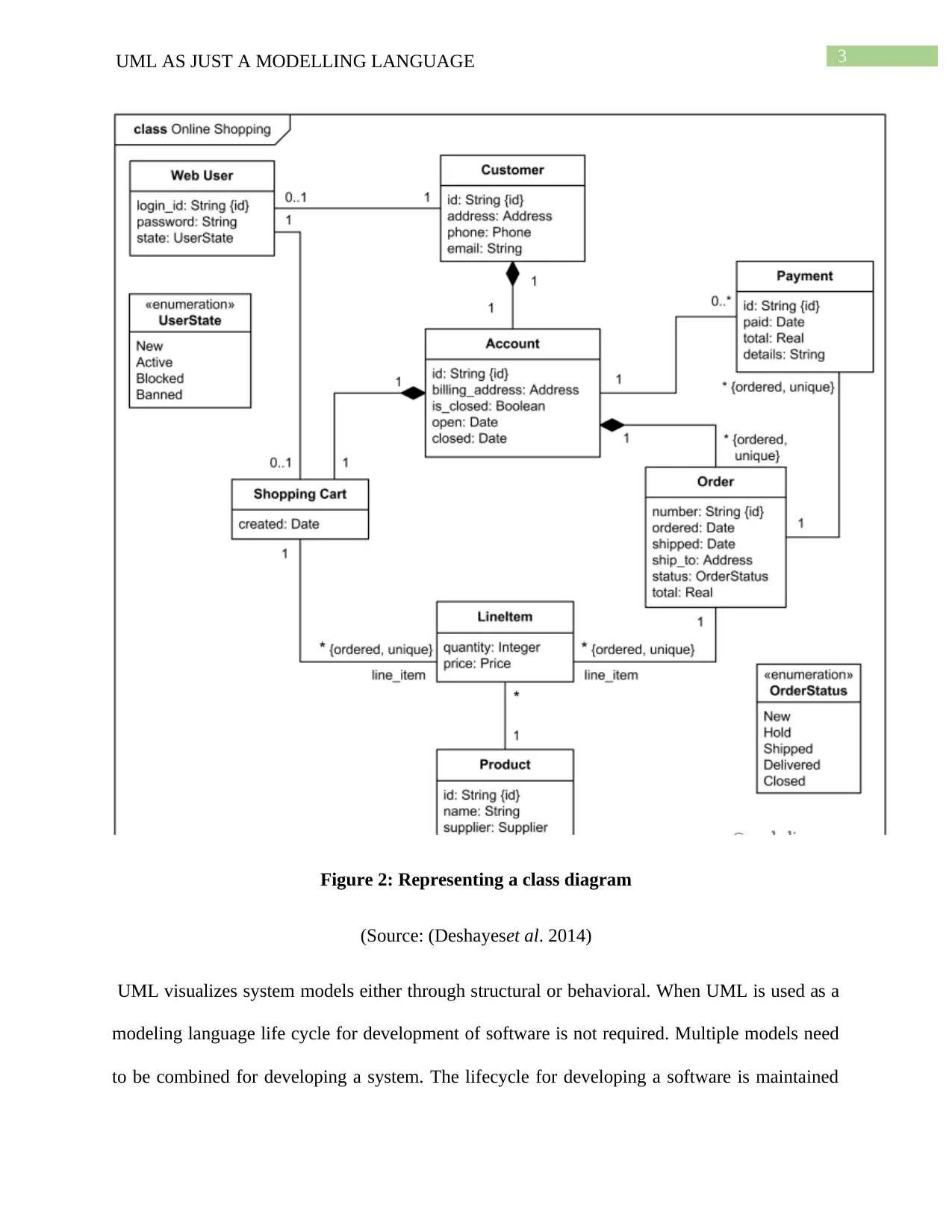
This essay explores the application of Unified Modeling Language (UML) as a modeling language within the context of project development lifecycles, particularly focusing on iterative and incremental approaches. It examines UML's role in system development, highlighting its three system models: object, dynamic, and functional, with use case and class diagrams illustrating online shopping systems. The discussion addresses whether UML should be exclusively used in iterative and incremental project lifecycles, emphasizing its process-independent nature while advocating for its suitability in use case-driven, architecture-centric processes. The essay further elaborates on the four phases of object-oriented development—Inception, Elaboration, Construction, and Transition—and concludes that UML diagrams are essential for defining project structure, class relationships, and the various stages of project development, especially in iterative lifecycles where requirements can be modified and UML classes adjusted accordingly, enabling successful software development through proper methodology selection. Desklib provides a platform to access similar solved assignments.
Document Page
Running Head: UML AS JUST A MODELLING LANGUAGE
UML as a Modelling Language
Name of the student:
Name of the university:
Author note:
tabler-icon-diamond-filled.svg

Paraphrase This Document

Need a fresh take? Get an instant paraphrase of this document with our AI Paraphraser
Document Page
1UML AS JUST A MODELLING LANGUAGE
Introduction:
This assignment will focus on the topic whether UML should be used only when the
project life-cycle is iterative and incremental. Deshayes et al. (2014) cited that UML is also
known as Unified Modelling Language. It is a modeling language that includes a set of diagrams.
By designing UML diagram software and system developers can construct specific visual design
for a particular software designing aspects. For example, if software designer want to develop a
program for railway ticket booking system,UML diagram helps to build an outline for that
particular ticket booking system (Torchianoet al. 2013). It is a collection of engineering practices
that prove successful in modeling complex and large systems. Graphical notations are mostly
used in UML to portray the design of software projects. It is mostly used in developing software
development processes and object oriented software. The system’s architectural blueprints are
visualized in a diagram using UML. The diagram might include components of the system,
describe running of the system and interaction of the components with one another. The
following paragraphs will enlighten on use of UML to define project life-cycle.
Discussion:
UML as just a modeling language:
UML as a modeling language is used for system development. It focuses on three
different system models. They are object model, dynamic model as well as functional model.
Functional model consists of Use Case diagram that describes system functionality using user
point of view (Mahmood and Lai 2013). The figure below represents an example of a use case
diagram related to online shopping.
Document Page
2UML AS JUST A MODELLING LANGUAGE
Figure 1: Representing an Use Case Diagram
(Source: Barenji,Barenji and Hashemipour 2014)
The object model includes Class diagram that describes system structure in terms of
associations, objects, attributes and operations. The dynamic model includes state machine
diagrams, interaction diagram as well as activity diagrams that describe system’s internal
behavior. The figure below represents an example of a class diagram related to online shopping
system.
Document Page
3UML AS JUST A MODELLING LANGUAGE
Figure 2: Representing a class diagram
(Source: (Deshayeset al. 2014)
UML visualizes system models either through structural or behavioral. When UML is used as a
modeling language life cycle for development of software is not required. Multiple models need
to be combined for developing a system. The lifecycle for developing a software is maintained
tabler-icon-diamond-filled.svg

Paraphrase This Document

Need a fresh take? Get an instant paraphrase of this document with our AI Paraphraser
Document Page
4UML AS JUST A MODELLING LANGUAGE
by implementing different UML models in the development process (Torchianoet al. 2013).
UML as a modeling language consists of various diagrams that can be used to develop software.
They are package diagram, composite diagram, object diagram, deployment diagram as well as
component diagram.
Life cycle in project development:
Project development is defined as a systematic process that consists of various
developmental stages. The total time taken in developing the project from initiation to
completion is known as the lifecycle of the project (Burghard,Stieglbauer and Korošec2016).
The project of developing the software should aim in meeting all requirements of the client. The
requirements should be analyzed before software design. Developing a software should also
follow a project life cycle. It has been argued that UML is not just a modeling language and can
be used in describing project lifecycle (Deshayeset al. 2014). However, others argue that it can
only be used when the project lifecycle is incremental and iterative.
Use of UML in project development lifecycle:
Unified Modeling Language is mainly process-independent, which means that it is not
tied to software development lifecycle. However, UML should be used in processes that will be
use case driven, incremental and iterative and architecture centric (Barenji,Barenji and
Hashemipour 2014). It is true that UML should be used only when the project life cycle is
incremental and iterative.
Stream of executable releases are managed by iterative process. Incremental process
involves continuous integration of system architecture so as to produce the releases. Each release
are improved in an incremental way than the previous release. This reduces the risk to the
Document Page
5UML AS JUST A MODELLING LANGUAGE
success of project. Software development lifecycle consists of four phases mainly inception,
transition, construction and elaboration (Lopataet al. 2015). The behavioral requirements of the
project can be structured using UML Case diagram. The UML diagram answers questions of the
project like who are the team members, the objectives of the project and what are the
qualifications and experience of the team members who are doing the project. UML diagrams are
included in system requirements specification document. The incremental and iterative
development approach starts with subdividing our project into small binary deliverables
(Deshayeset al. 2014). Therefore UML finds application here where the project is broken down
into short deliverables and each project can be represented by a diagram. There are certain rules
that should be followed while creating UML diagram of the project (Burghard,Stieglbauer and
Korošec2016). They are the diagram should be vertical and should represent features of the
project. Additionally they should be demonstrable and executable, simple and complete as well
as they should be same in terms of manpower.
The four phases that are included in the life cycle of Object-Oriented development are
Inception, Elaboration, Construction and Transition (Barenji,Barenji and Hashemipour2014).
Inception is the first process where the project team members and customers agree on what topic
to be built. Elaboration is the second process where architecture and design needs to be
confirmed by the team members. Construction is the third process where the functional system
creates iterative implementation (Mahmood and Lai 2013). The last process is transition where
team and customer choose the defect correction, delivery and tunes to ensure customer
acceptance.
Different form of communication dominates each of these phase. The flow of
communication varies with that of phase. The communication focuses outward toward the
Document Page
6UML AS JUST A MODELLING LANGUAGE
customer anyone who represents the users in the inception phase(Benavides et al. 2013). The
customers can be either a contracting agency, the users themselves or the marketing department.
The communication focuses inward in the construction and elaboration phases (Shaker 2013).
The communication again focuses outward in the transition phase. The communication between
the customer and the team is maintained in each phase. The difference between the phases is a
matter of emphasis.
Figure 3: Phases in Object-Oriented Development
(Source:Torchianoet al. 2013)
A use case diagram is designed to demonstrate or visualize for a particular system
behavior along with its users specifications. By designing a use case diagram for a particular
system, software developer can demonstrate the system’s functionalities, classes, attributes, etc.
The design in addition show the way objects of the elements collaborate and accomplish the
behavior documented in the before use case diagram (Benavides et al. 2013). The process view
is another version of design view. The implementation view is also called physical view and
implementation view captures the file that are consisted in the system and the way these files are
tabler-icon-diamond-filled.svg

Paraphrase This Document

Need a fresh take? Get an instant paraphrase of this document with our AI Paraphraser
Document Page
7UML AS JUST A MODELLING LANGUAGE
related to the design.The project management stakeholders communicate between themselves by
using UML artifacts that includes deployment diagrams.
Conclusion:
From the above discussions, it can be concluded that the UML diagram should be used
when the project life cycle is incremental and iterative. UMLs are required for developing the
project structure. Relation between different classes of the software is defined by UML
diagrams. The attributes of the different classes are defined in the UML diagram. The various
stages of development of the project is defined by the project development lifecycle. The
development of software consists of five stages. Requirement analysis is one of the stages in
project development that is displayed in the UML diagram. The client can modify the
requirements in iterative lifecycle of the project. The UML classes can be modified in this case.
In other words, the structure of the program is defined by the UML language. UML has the
ability to design a software. The abstraction in the software is represented graphically. It can be
concluded that the software development can be done by using UML diagrams that describes
project lifecycle of the development activities. The successful development of the project can be
achieved by proper selection of project methodologies.
Document Page
8UML AS JUST A MODELLING LANGUAGE
References:
Barenji, A.V., Barenji, R.V. and Hashemipour, M., 2014. A frameworks for structural modelling
of an RFID-enabled intelligent distributed manufacturing control system. South African Journal
of Industrial Engineering, 25(2), pp.48-66.
Benavides, D., Felfernig, A., Galindo, J.A. and Reinfrank, F., 2013, June. Automated analysis in
feature modelling and product configuration. In International Conference on Software Reuse (pp.
160-175). Springer, Berlin, Heidelberg.
Burghard, C., Stieglbauer, G. and Korošec, R., 2016. Introducing MDML-A Domain-specific
Modelling Language for Automotive Measurement Devices. In Joint Proceedings of the
International Workshop on Quality Assurance in Computer Vision and the International
Workshop on Digital Eco-Systems co-located with the 28th International Conference on Testing
Software and Systems (ICTSS) (pp. 28-31).
Deshayes, R., Meyers, B., Mens, T. and Vangheluwe, H., 2014. ProMoBox in Practice: A Case
Study on the GISMO Domain-Specific Modelling Language. In MPM@ MoDELS(pp. 21-30).
Lopata, A., Ambraziunas, M., Veitaite, I., Masteika, S. and Butleris, R., 2015. SysML and UML
models usage in knowledge based MDA process. Elektronikairelektrotechnika, 21(2), pp.50-58.
Mahmood, S. and Lai, R., 2013. RE-UML: A component-based system requirements analysis
language. The Computer Journal, 56(7), pp.901-922.
Shaker, P., 2013. A feature-oriented modelling language and a feature-interaction taxonomy for
product-line requirements.
Document Page
9UML AS JUST A MODELLING LANGUAGE
Torchiano, M., Tomassetti, F., Ricca, F., Tiso, A. and Reggio, G., 2013. Relevance, benefits, and
problems of software modelling and model driven techniques—A survey in the Italian
industry. Journal of Systems and Software, 86(8), pp.2110-2126.
chevron_up_icon
1 out of 10
circle_padding
hide_on_mobile
zoom_out_icon
[object Object]