IMAT5205 - System Analysis and Design: UML Modeling for Tour System
VerifiedAdded on 2023/05/30
|10
|2362
|199
Report
AI Summary
This report provides a comprehensive analysis and design of a Tour Management System for World Wide Coach Tours, utilizing UML diagrams such as analysis class diagrams, sequence diagrams, and communication diagrams to model the 'Record New Tour' use case. It evaluates the role of CASE tools in system development, highlighting their impact on system analysts and designers. The report also emphasizes the importance of UML modeling in enhancing system quality and facilitating communication between IT and business teams. Concluding with the significance of various diagrams in system analysis and the benefits of CASE tools in reducing development time and improving product quality.

SYSTEM ANALYSIS AND DESIGN 1
System Analysis and Design
Student Name
Institutional Affiliation
System Analysis and Design
Student Name
Institutional Affiliation
Paraphrase This Document
Need a fresh take? Get an instant paraphrase of this document with our AI Paraphraser
SYSTEM ANALYSIS AND DESIGN 2
Table of Contents
Introduction......................................................................................................................................3
Part 1. Use Case Realization for the ‘Record New Tour’ Use Case................................................3
Analysis Class Diagram...............................................................................................................3
Communication Diagram.............................................................................................................5
Part 2. Sequence Diagram................................................................................................................7
Part 3. Evaluation.............................................................................................................................8
Conclusion.......................................................................................................................................9
Reference List................................................................................................................................11
SYSTEM ANALYSIS AND DESIGN 3
Introduction
World Wide Coach Tours is a tour guide company that is in UK and operate coach tours within
UK and in other cities in Europe. The company has existing systems in place that are used to
mange the various aspects of the business such as booking details, tour information, driver
information among others. The company would like to develop a comprehensive Tour
Management System that will meet the new requirements. This document will describe analysis
class diagram, sequence diagram, and communication diagram got the ‘Record New Tour’ use
case. Also, CASE tools will be discussed in relation to the roles of system analysts and
designers.
Part 1. Use Case Realization for the ‘Record New Tour’ Use Case
Analysis Class Diagram
Analysis class diagram is used in mapping clearly the structure of a system by modelling system
operations, attributes, classes, and object relationships (Ambler, 2017). It is quite simple creating
an activity diagram, but it is important to understand how the system operates. Analysis class
diagrams are very important in system analysis because they describe information system data
models regardless of its complexity, give a better understanding of application schematics,
creates comprehensive charts that highlights the specific sections to be implemented, offer
implementation-independent explanation of system components, and express system need
visually and share such information across the business (Turan, 2015).
⊘ This is a preview!⊘
Do you want full access?
Subscribe today to unlock all pages.
Trusted by 1+ million students worldwide

SYSTEM ANALYSIS AND DESIGN 4
Figure 1: Analysis Class Diagram
(Source: Author)
Summary
Before drawing the activity class diagram, it was necessary to understand its various
components. The primary component of an activity is the activity itself which is a function
carried out by the system. After determining the different activities within the system, it is
important to understand how they are associated with conditions and constraints. One was to
identify the actions- a series of steps that a program or a user takes to carry out a specific
activity. These actions are represented using round-edged rectangles. Secondly, was to identify
the different decision nodes of the system. These are conditional branches in the system flow that
are symbolized by a diamond (Ma and Liu, 2011). Thirdly, it is necessary to determine the
Paraphrase This Document
Need a fresh take? Get an instant paraphrase of this document with our AI Paraphraser
SYSTEM ANALYSIS AND DESIGN 5
different system control flows that show flow between steps. Additionally, it is necessary to
identify the start node and the end node representing the beginning and the final step in the
activity respectively. The activity class diagram was made by joining and connecting the
different activity states. All the action flows are symbolized by arrows showing transition from
one state to another. It is important to make such choices to ensure that a proper and well-
structured activity class diagram is drawn and conveys relevant and clear message to the target
audience.
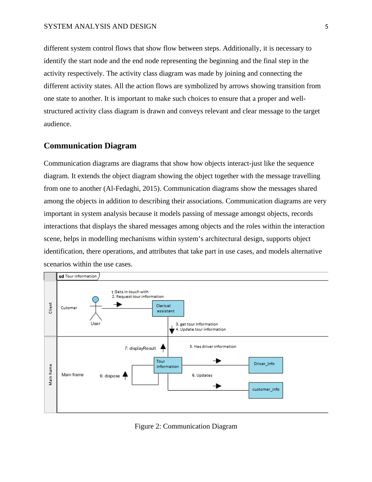
Communication Diagram
Communication diagrams are diagrams that show how objects interact-just like the sequence
diagram. It extends the object diagram showing the object together with the message travelling
from one to another (Al-Fedaghi, 2015). Communication diagrams show the messages shared
among the objects in addition to describing their associations. Communication diagrams are very
important in system analysis because it models passing of message amongst objects, records
interactions that displays the shared messages among objects and the roles within the interaction
scene, helps in modelling mechanisms within system’s architectural design, supports object
identification, there operations, and attributes that take part in use cases, and models alternative
scenarios within the use cases.
Figure 2: Communication Diagram
different system control flows that show flow between steps. Additionally, it is necessary to
identify the start node and the end node representing the beginning and the final step in the
activity respectively. The activity class diagram was made by joining and connecting the
different activity states. All the action flows are symbolized by arrows showing transition from
one state to another. It is important to make such choices to ensure that a proper and well-
structured activity class diagram is drawn and conveys relevant and clear message to the target
audience.
Communication Diagram
Communication diagrams are diagrams that show how objects interact-just like the sequence
diagram. It extends the object diagram showing the object together with the message travelling
from one to another (Al-Fedaghi, 2015). Communication diagrams show the messages shared
among the objects in addition to describing their associations. Communication diagrams are very
important in system analysis because it models passing of message amongst objects, records
interactions that displays the shared messages among objects and the roles within the interaction
scene, helps in modelling mechanisms within system’s architectural design, supports object
identification, there operations, and attributes that take part in use cases, and models alternative
scenarios within the use cases.
Figure 2: Communication Diagram
SYSTEM ANALYSIS AND DESIGN 6
(Source: Author)
Summary
Communication diagrams offers benefits almost like those of a sequence diagram. However, it is
important to establish how the various components interact and communicate with one another
rather than focusing on the sequence of events as in the case of a sequence diagram. First, while
drawing a communication diagram, I modelled the logic of sophisticated operations, functions,
and/or procedures to reduce the complexity. Secondly, it was important to determine how
commands and instructions are sent and received between process components or objects to
make it easy to identify if the commands have been sent or not (Biswal, Barpanda and
Mohapatra, 2010). Thirdly, it is necessary to visualize the consequences of specific interactions
among the different process components to have all the possible outcomes associated with a
specific interaction. By making the above decisions, drawing the communication diagram
became easier.
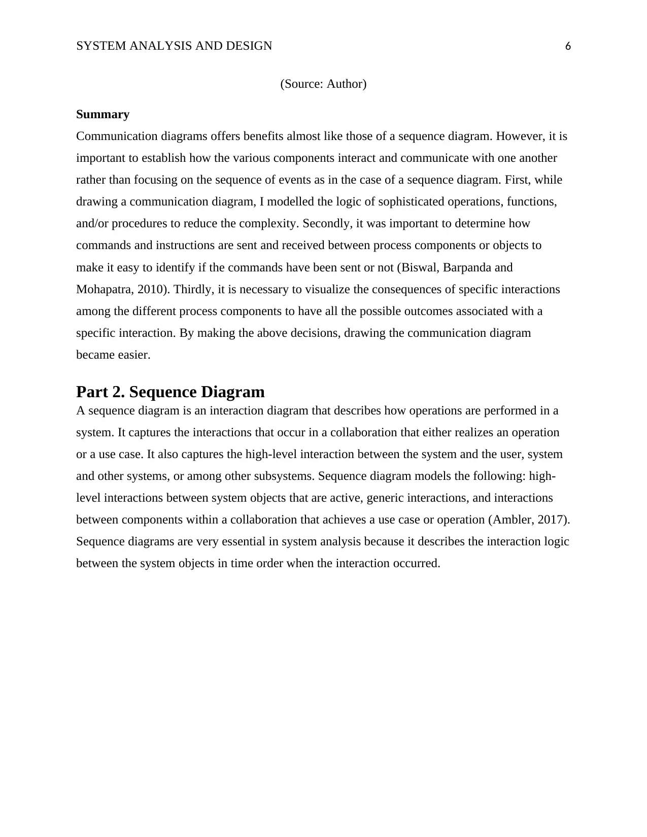
Part 2. Sequence Diagram
A sequence diagram is an interaction diagram that describes how operations are performed in a
system. It captures the interactions that occur in a collaboration that either realizes an operation
or a use case. It also captures the high-level interaction between the system and the user, system
and other systems, or among other subsystems. Sequence diagram models the following: high-
level interactions between system objects that are active, generic interactions, and interactions
between components within a collaboration that achieves a use case or operation (Ambler, 2017).
Sequence diagrams are very essential in system analysis because it describes the interaction logic
between the system objects in time order when the interaction occurred.
(Source: Author)
Summary
Communication diagrams offers benefits almost like those of a sequence diagram. However, it is
important to establish how the various components interact and communicate with one another
rather than focusing on the sequence of events as in the case of a sequence diagram. First, while
drawing a communication diagram, I modelled the logic of sophisticated operations, functions,
and/or procedures to reduce the complexity. Secondly, it was important to determine how
commands and instructions are sent and received between process components or objects to
make it easy to identify if the commands have been sent or not (Biswal, Barpanda and
Mohapatra, 2010). Thirdly, it is necessary to visualize the consequences of specific interactions
among the different process components to have all the possible outcomes associated with a
specific interaction. By making the above decisions, drawing the communication diagram
became easier.
Part 2. Sequence Diagram
A sequence diagram is an interaction diagram that describes how operations are performed in a
system. It captures the interactions that occur in a collaboration that either realizes an operation
or a use case. It also captures the high-level interaction between the system and the user, system
and other systems, or among other subsystems. Sequence diagram models the following: high-
level interactions between system objects that are active, generic interactions, and interactions
between components within a collaboration that achieves a use case or operation (Ambler, 2017).
Sequence diagrams are very essential in system analysis because it describes the interaction logic
between the system objects in time order when the interaction occurred.
⊘ This is a preview!⊘
Do you want full access?
Subscribe today to unlock all pages.
Trusted by 1+ million students worldwide
SYSTEM ANALYSIS AND DESIGN 7
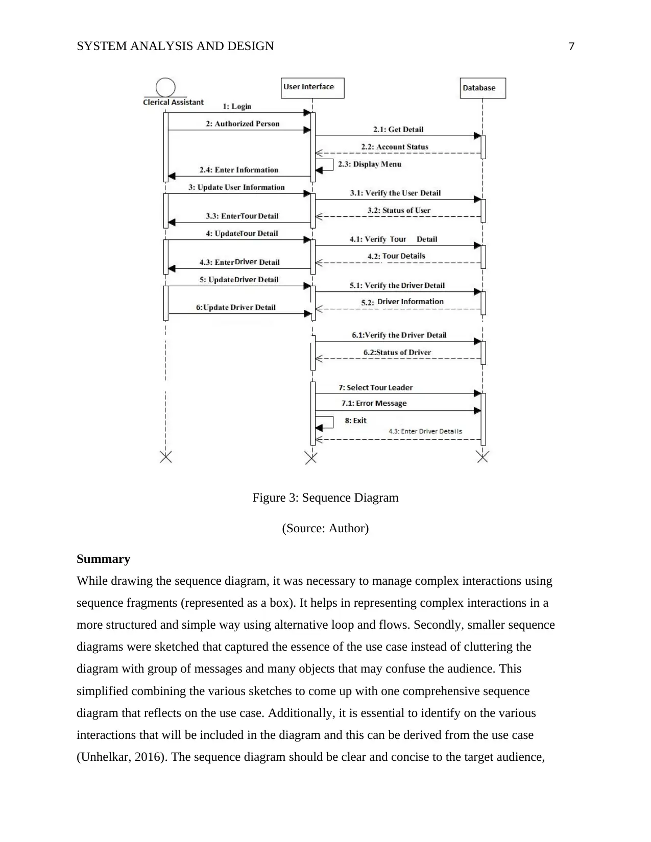
Figure 3: Sequence Diagram
(Source: Author)
Summary
While drawing the sequence diagram, it was necessary to manage complex interactions using
sequence fragments (represented as a box). It helps in representing complex interactions in a
more structured and simple way using alternative loop and flows. Secondly, smaller sequence
diagrams were sketched that captured the essence of the use case instead of cluttering the
diagram with group of messages and many objects that may confuse the audience. This
simplified combining the various sketches to come up with one comprehensive sequence
diagram that reflects on the use case. Additionally, it is essential to identify on the various
interactions that will be included in the diagram and this can be derived from the use case
(Unhelkar, 2016). The sequence diagram should be clear and concise to the target audience,
Paraphrase This Document
Need a fresh take? Get an instant paraphrase of this document with our AI Paraphraser
SYSTEM ANALYSIS AND DESIGN 8
therefore avoid using many details or too much information in the diagram. It was also ensured
that no blank spaces existed between the use case text and the message arrow to ensure that the
audience could read the diagram easily.
Part 3. Evaluation
A Computer-Aided Software Engineering (CASE) tool refers to automated software tools that
are used to develop and maintain different system projects. They are used to automated system
development life cycle activities and can be used by system analysts, engineers, and project
managers during development of a software system as that of the World-Wide Tours case (Biffl,
et al., 2009). There exist several CASE tools that can be used to simplify the system
development process such as design tools, analysis tools, documentation tools, database
management tools, project management tools among others. All these tools can be adopted to
accelerate the development of the World-Wide Tours System. The CASE tools support
numerous activities in SDLC including planning, analysis, design, implementation, testing,
maintenance, and documentation process.
Many system designers and analysts are still resisting the use of CASE tools because of the fear
of losing control of the analysis and design processes. Even though these tools reduce money and
time spent of projects and improved system quality, designers still prefer the use of the
traditional pen and paper. However, CASE tools do not necessarily replace system analysts and
designers, but it makes their work easier (Novakovic, Deletic and Deletic, 2010). CASE tools
enable the designers to input system requirements and the CASE tool can help generate the code.
This will facilitate the designer to focus more on system architecture rather than code. Many
CASE tools support reverse engineering where code of an existing system can be converted to
design specifications. CASE tools offer better synchronization of the model design and
implementation. With CASE tools analysts will have less work to do because much of the tasks
is done by the software. Some of the tasks supported by CASE tools that were being done by
system analysts and designers previously include requirement analysis, design specifications,
better documentation among others. However, these CASE tools should be used properly if the
development team wants to achieve the most ideal outcome. This can be achieved by ensuring
that the most appropriate and relevant CASE tool has been chosen and necessary training has
been carried out for the development team. As such, system analysts and designers are still
crucial in the development process.

SYSTEM ANALYSIS AND DESIGN 9
System analysts and designers have in the recent past greatly adopted UML modelling in system
development. This is because UML is a powerful tool that enhances the quality of system
analysis and design resulting to development of a quality system (Wells, 2009). By employing
the use of UML modelling regularly and repeatedly in analysis and design, a greater insight will
be attained between the IT team and the business team concerning the requirements and
processes that needs to take place within the system to address those requirements. UML
modelling, by use case analysis, can be used to validate the requirements derived from the
overall system objectives. System requirements can further be refined subsequently using
sequence diagrams, class diagrams, use case scenarios, state chart diagrams and many other
UML models. Better results can be achieved through iteration of these processes to get a more
detailed system design with concise and clear relationships defined in the UML documents.
Therefore, UML modelling is a great tool for system analysts and designers to come up with
more comprehensive requirements and system design that can be translated into development of
a quality software or application system. UML diagrams are very important because they give a
rough picture of how the system will look like or operate in ensuring that the business
requirements have been met (Sharma, 2018).
Conclusion
There are several diagrams that are very important in system analysis such as analysis class
diagram which is used they describe information system data models regardless of its
complexity, give a better understanding of application schematics, creates comprehensive charts
that highlights the specific sections to be implemented. Another diagram is the communication
diagrams which is used to model how messages are passed amongst objects, records interactions
that displays the shared messages among objects and the roles within the interaction scene, helps
in modelling mechanisms within system’s architectural design, supports object identification,
there operations, and attributes that take part in use cases, and models alternative scenarios
within the use cases. Additionally, CASE tools can be employed in system analysis to reduce the
time and cost in system development and improve the quality of the product developed.
⊘ This is a preview!⊘
Do you want full access?
Subscribe today to unlock all pages.
Trusted by 1+ million students worldwide

SYSTEM ANALYSIS AND DESIGN 10
Reference List
Al-Fedaghi, S. (2015). On Collaboration in Software: Annotation vs. Flow-Based Diagrams.
Journal of Software, 10(11), 1327–1335. http://doi.org/10.17706//jsw.10.11.1327-1335
Ambler, S. W. (2017). UML Use-Case Diagrams. The Elements of UML™ 2.0 Style, 33–46.
http://doi.org/10.1017/cbo9780511817533.005
Biffl, S., Ferstl, C., Höllwieser, C., & Moser, T. (2009). EVALUATION OF CASE TOOL
METHODS AND PROCESSES - An Analysis of Eight Open-source CASE Tools. Proceedings
of the 11th International Conference on Enterprise Information.
http://doi.org/10.5220/0001865700410048
Biswal, B. N., Barpanda, S. S., & Mohapatra, D. P. (2010). A Novel Approach for Optimized
Test Case Generation Using Activity and Collaboration Diagram. International Journal of
Computer Applications, 1(14), 67–71. http://doi.org/10.5120/299-463
Ma, Q., & Liu, L. (2011). The Technology Acceptance Model. End-User Computing.
http://doi.org/10.4018/9781599049458.ch079
Novakovic, I., Deletic, V., & Deletic, M. (2010). Information system development with the
enhancement of CASE tools functionality. Facta Universitatis - Series: Electronics and
Energetics, 23(1), 55–61. http://doi.org/10.2298/fuee1001055n
Sharma, M. (2018). Role of CASE tools in system development. Retrieved December 23, 2018,
from http://www.biyanicolleges.org/role-of-case-tools-in-system-development/
Turan, M. (2015). Integrating Software Metrics with UML Class Diagrams. Lecture Notes on
Software Engineering, 3(3), 220–224. http://doi.org/10.7763/lnse.2015.v3.194
Unhelkar, B. (2016). Activity Diagrams, Interaction Overview Diagrams, and Business Process
Models. Software Engineering with UML, 109–126. http://doi.org/10.1201/9781351235181-7
Wells, C. J. (2009). CASE Tools. Retrieved December 23, 2018, from
http://www.technologyuk.net/software-development/sad/case-tools.shtml
1 out of 10
Related Documents


Your All-in-One AI-Powered Toolkit for Academic Success.
+13062052269
info@desklib.com
Available 24*7 on WhatsApp / Email
![[object Object]](/_next/static/media/star-bottom.7253800d.svg)
Unlock your academic potential
Copyright © 2020–2026 A2Z Services. All Rights Reserved. Developed and managed by ZUCOL.