Exploring 3-Bit Analog-to-Digital Converter Design and Function

Verified

Added on  2023/06/11

|4
|507
|368
Report
AI Summary
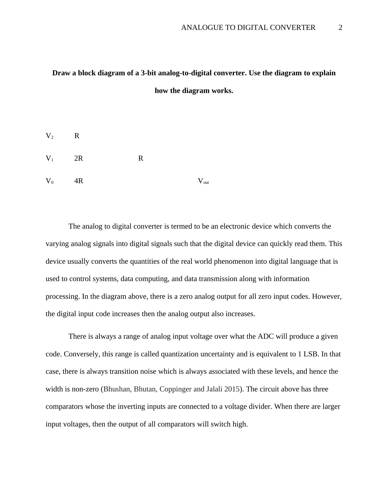
This report details the functionality of a 3-bit analog-to-digital converter (ADC), explaining how it converts analog signals into digital signals. It includes a block diagram illustrating the components, such as comparators and a voltage divider, and describes how the ADC operates. The document explains the concept of quantization uncertainty and transition noise associated with ADC levels. It also provides an example calculation for converting a specific voltage (7/16 volts) using a resolution of 1/8 volts per bit, along with the number of clock cycles required for the conversion, emphasizing the step-by-step MSB conversion process. The report references research on time-stretched analog-to-digital conversion and asynchronous analog-to-digital converters.
tabler-icon-diamond-filled.svg

Contribute Materials

Your contribution can guide someone’s learning journey. Share your documents today.
Document Page
ANALOGUE TO DIGITAL CONVERTER 1
Analogue to Digital Converter
Student’s Name
Institutional Affiliation
Date
tabler-icon-diamond-filled.svg

Secure Best Marks with AI Grader

Need help grading? Try our AI Grader for instant feedback on your assignments.
Document Page
ANALOGUE TO DIGITAL CONVERTER 2
Draw a block diagram of a 3-bit analog-to-digital converter. Use the diagram to explain
how the diagram works.
V2 R
V1 2R R
V0 4R Vout
The analog to digital converter is termed to be an electronic device which converts the
varying analog signals into digital signals such that the digital device can quickly read them. This
device usually converts the quantities of the real world phenomenon into digital language that is
used to control systems, data computing, and data transmission along with information
processing. In the diagram above, there is a zero analog output for all zero input codes. However,
the digital input code increases then the analog output also increases.
There is always a range of analog input voltage over what the ADC will produce a given
code. Conversely, this range is called quantization uncertainty and is equivalent to 1 LSB. In that
case, there is always transition noise which is always associated with these levels, and hence the
width is non-zero (Bhushan, Bhutan, Coppinger and Jalali 2015). The circuit above has three
comparators whose the inverting inputs are connected to a voltage divider. When there are larger
input voltages, then the output of all comparators will switch high.
Document Page
ANALOGUE TO DIGITAL CONVERTER 3
Assume a resolution of 1/8 volts per bit, show how the 3-bit ADC will convert 7/16 volts.
Since n is the number of bits in the ADC. This ADC has therefore 3 bits. In that case,
there are 23 = 8 states
(7/15)/8 = 0.0583mV
Calculate also the number of clock cycles required to perform the conversion
A 3-bit conversion usually takes at least two clock cycles which is equivalent to 1.5 us.
For the case of this conversion, it will, therefore, require three clock cycles to perform the
conversion. As an illustration, it always performs the MSB conversion where it asks if the value
is more than half of the reference voltage and hence sets the MSB to 1 if yes (Ahn and Kim
2014). After that, it subtracts either half the reference from input value and does that for every
bit.
Document Page
ANALOGUE TO DIGITAL CONVERTER 4
References
Bhushan, A. S., Coppi Bhutan, A.S., Coppinger, F. and Jalali, B., 2015. Time-stretched analog-
to-digital conversion. Electronics Letters, 34(9), pp.839-841. nger, F., & Jalali, B. (1998).
Time-stretched analog-to-digital conversion. Electronics Letters, 34(9), 839-841.
Ahn, S.J. and Kim, D.M., 2014. Asynchronous analog-to-digital converter for single-electron
circuits. Electronics Letters, 34(2), pp.172-173.
chevron_up_icon
1 out of 4
circle_padding
hide_on_mobile
zoom_out_icon
logo.png

Your All-in-One AI-Powered Toolkit for Academic Success.

Available 24*7 on WhatsApp / Email

[object Object]