University E-Food Cart System: Analysis and Design Report
VerifiedAdded on 2022/10/02
|15
|1286
|204
Report
AI Summary
This report presents the analysis and design of an E-Food Cart food delivery system, developed to streamline food ordering from a college canteen. The report begins with an introduction, followed by a discussion of system analysis and design concepts, and the System Development Life Cycle (SDLC). It then delves into system modeling, utilizing various diagrammatic tools like Use Case, Sequence, Data Flow Diagram (DFD), and Entity Relationship Diagram (ERD) to illustrate the system's functionality, data flow, and database structure. The report also includes interface mockups for the menu, login, and order report. The conclusion summarizes the successful application of these analysis and design techniques, highlighting the importance of SDLC in developing the system, and the use of modelling techniques to define the direction and goals of the system.
Running head: E-FOOD CART: FOOD DELIVERY SYSTEM: ANALYSIS AND DESIGN
E-Food Cart: Food Delivery System: Analysis and Design
Name of the Student
Name of the University
Author Note
E-Food Cart: Food Delivery System: Analysis and Design
Name of the Student
Name of the University
Author Note
Paraphrase This Document
Need a fresh take? Get an instant paraphrase of this document with our AI Paraphraser
1E-FOOD CART: FOOD DELIVERY SYSTEM: ANALYSIS AND DESIGN
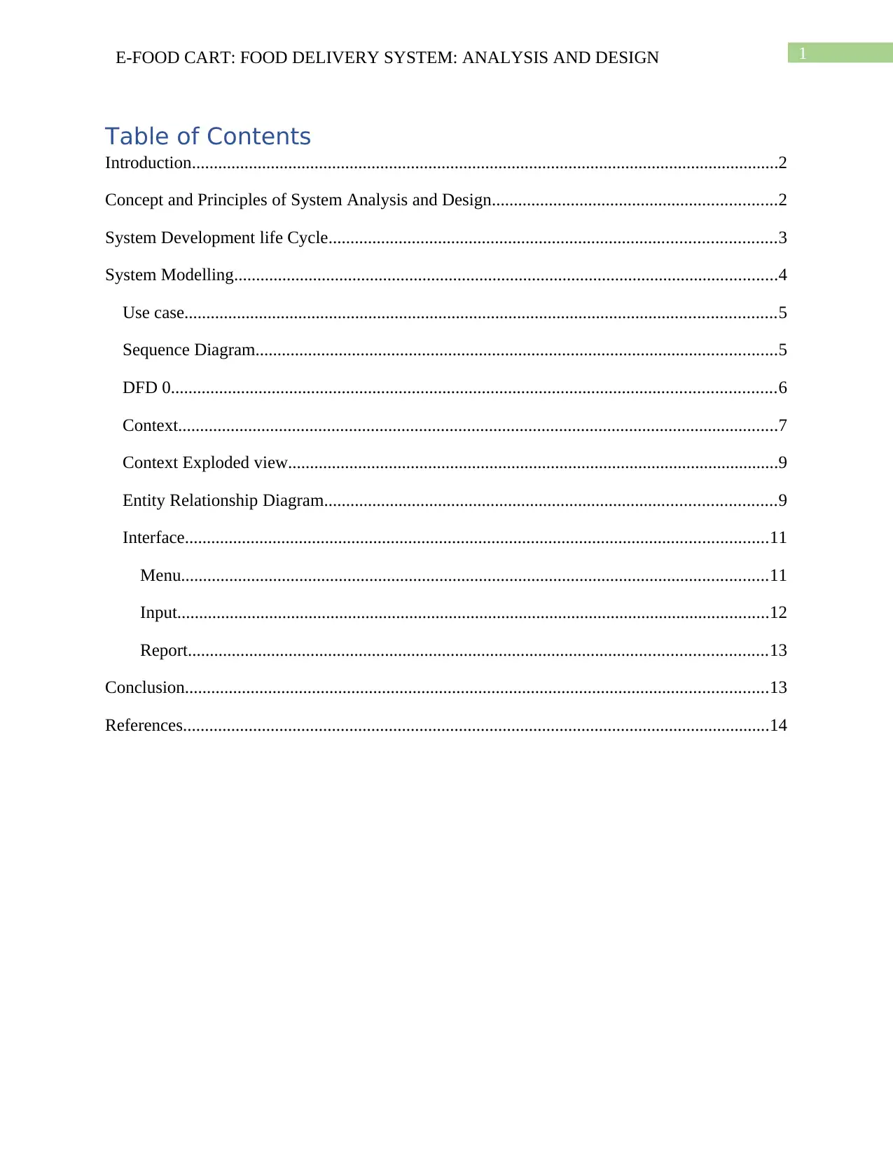
Table of Contents
Introduction......................................................................................................................................2
Concept and Principles of System Analysis and Design.................................................................2
System Development life Cycle......................................................................................................3
System Modelling............................................................................................................................4
Use case.......................................................................................................................................5
Sequence Diagram.......................................................................................................................5
DFD 0..........................................................................................................................................6
Context.........................................................................................................................................7
Context Exploded view................................................................................................................9
Entity Relationship Diagram.......................................................................................................9
Interface.....................................................................................................................................11
Menu......................................................................................................................................11
Input.......................................................................................................................................12
Report....................................................................................................................................13
Conclusion.....................................................................................................................................13
References......................................................................................................................................14
2E-FOOD CART: FOOD DELIVERY SYSTEM: ANALYSIS AND DESIGN
Introduction
A system is developed after the full analysis of its users and objectives. On the basis of
the analysis the design has been included in the system development. Also, the whole
development is no a single and easy task. The development is divided in to several parts as
stages. Different stages provide the different aspects of outputs of the system. In this case of E-
food cart, a system is needed to be developed that delivers the food items from the canteen of the
college to the student’s room directly. The system is needed to receive the orders through online
where a student can log in and order. Tracking and cart features are also to be provided in the
proposed system. The report intends to discuss the analysis and design for the newly proposed
system E-FoodCart. The design has been done using some modern modelling techniques.
Concept and Principles of System Analysis and Design
Analysis and design of system is a process of gathering the factual data, identifying the
system requirements, its problems and the solution. The main purpose of the system analysis is
to identifying the usability of the system where the objectives of the systems are defined. Later
all the objectives define collectively a particular goal for the system development (Dennis,
Wixom and Roth 2018). Where the Design refers to the system design where the different type
of designs is developed with the help of the modern modelling techniques. A system can
interaction, interdependence, integration, central objective etc. as the properties. Design helps in
finding and correcting and analytical errors of the developing system (Johansson‐Sköldberg,
Woodilla and Çetinkaya 2013). The system development is a long a restless process, hence the
development happens in steps or stages or phases.
⊘ This is a preview!⊘
Do you want full access?
Subscribe today to unlock all pages.

Trusted by 1+ million students worldwide
3E-FOOD CART: FOOD DELIVERY SYSTEM: ANALYSIS AND DESIGN
System Development life Cycle (SDLC)
SDLC is the whole time period that a system takes to become fully developed or ready
for deployment. The SDLC consists some important stages for the system development that
requires for the new system. The no and type of phases totally depends on the type of project,
however, there are some predefined models are present for the system development (Mishra and
Dubey 2013). The models are waterfall, spiral, dynamic systems development methodology
(DSDM) etc. The waterfall model is very widely used method for the system development. The
development is consisting of six phases named analysis, design, integration, implementation and
testing, deployment and maintenance. All these phases are achieved step by step in the waterfall
model. Each phase’s output is Next’s input for the initiation of the phase (Kumar and Yadav
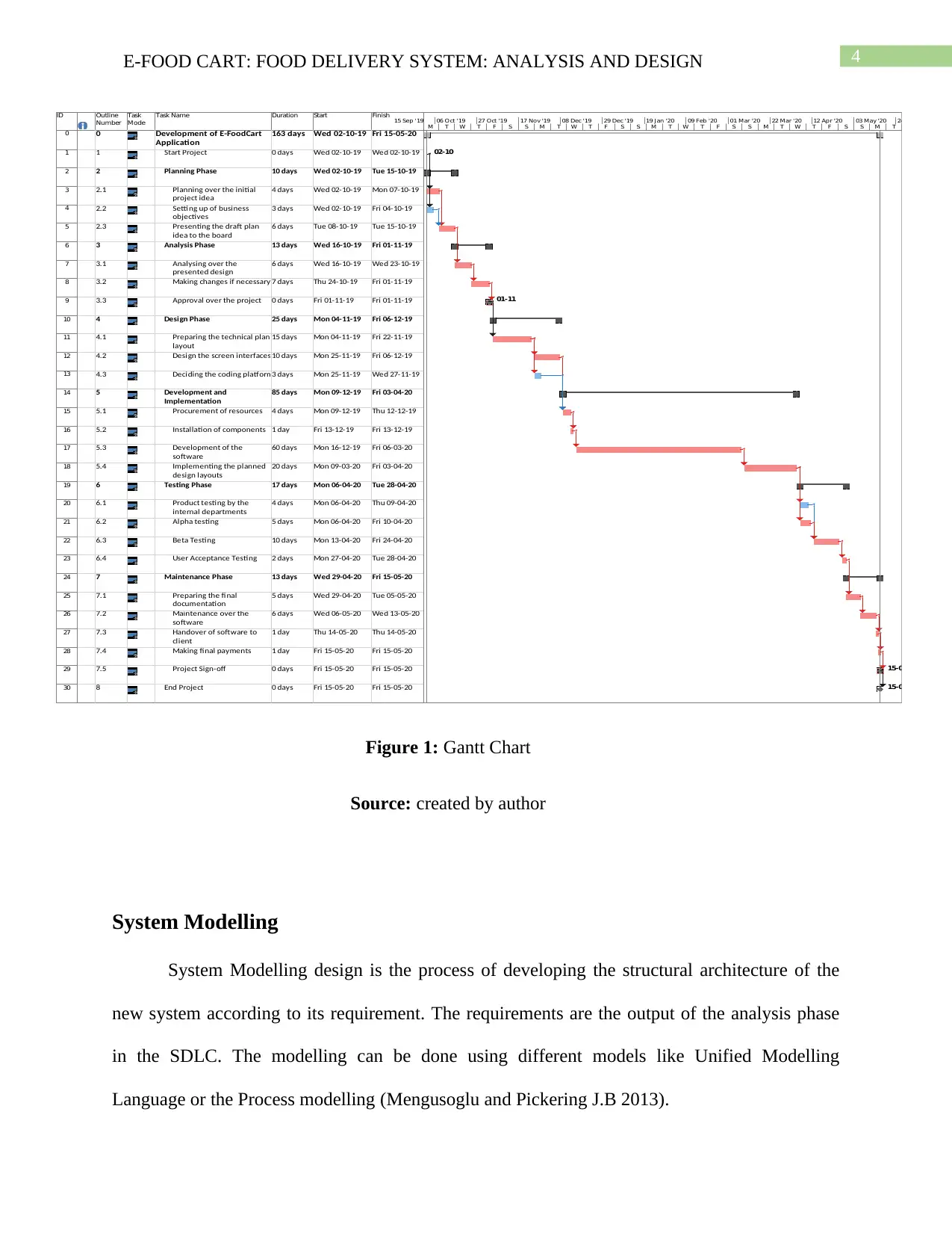
2017). The Gantt in figure 1. Showing the phases and its software development life cycle
timeline.
Paraphrase This Document
Need a fresh take? Get an instant paraphrase of this document with our AI Paraphraser
4E-FOOD CART: FOOD DELIVERY SYSTEM: ANALYSIS AND DESIGN
ID Outline
Number
Task
Mode
Task Name Duration Start Finish
0 0 Development of E-FoodCart
Application
163 days Wed 02-10-19 Fri 15-05-20
1 1 Start Project 0 days Wed 02-10-19 Wed 02-10-19
2 2 Planning Phase 10 days Wed 02-10-19 Tue 15-10-19
3 2.1 Planning over the initial
project idea
4 days Wed 02-10-19 Mon 07-10-19
4 2.2 Setting up of business
objectives
3 days Wed 02-10-19 Fri 04-10-19
5 2.3 Presenting the draft plan
idea to the board
6 days Tue 08-10-19 Tue 15-10-19
6 3 Analysis Phase 13 days Wed 16-10-19 Fri 01-11-19
7 3.1 Analysing over the
presented design
6 days Wed 16-10-19 Wed 23-10-19
8 3.2 Making changes if necessary 7 days Thu 24-10-19 Fri 01-11-19
9 3.3 Approval over the project 0 days Fri 01-11-19 Fri 01-11-19
10 4 Design Phase 25 days Mon 04-11-19 Fri 06-12-19
11 4.1 Preparing the technical plan
layout
15 days Mon 04-11-19 Fri 22-11-19
12 4.2 Design the screen interfaces10 days Mon 25-11-19 Fri 06-12-19
13 4.3 Deciding the coding platform3 days Mon 25-11-19 Wed 27-11-19
14 5 Development and
Implementation
85 days Mon 09-12-19 Fri 03-04-20
15 5.1 Procurement of resources 4 days Mon 09-12-19 Thu 12-12-19
16 5.2 Installation of components 1 day Fri 13-12-19 Fri 13-12-19
17 5.3 Development of the
software
60 days Mon 16-12-19 Fri 06-03-20
18 5.4 Implementing the planned
design layouts
20 days Mon 09-03-20 Fri 03-04-20
19 6 Testing Phase 17 days Mon 06-04-20 Tue 28-04-20
20 6.1 Product testing by the
internal departments
4 days Mon 06-04-20 Thu 09-04-20
21 6.2 Alpha testing 5 days Mon 06-04-20 Fri 10-04-20
22 6.3 Beta Testing 10 days Mon 13-04-20 Fri 24-04-20
23 6.4 User Acceptance Testing 2 days Mon 27-04-20 Tue 28-04-20
24 7 Maintenance Phase 13 days Wed 29-04-20 Fri 15-05-20
25 7.1 Preparing the final
documentation
5 days Wed 29-04-20 Tue 05-05-20
26 7.2 Maintenance over the
software
6 days Wed 06-05-20 Wed 13-05-20
27 7.3 Handover of software to
client
1 day Thu 14-05-20 Thu 14-05-20
28 7.4 Making final payments 1 day Fri 15-05-20 Fri 15-05-20
29 7.5 Project Sign-off 0 days Fri 15-05-20 Fri 15-05-20
30 8 End Project 0 days Fri 15-05-20 Fri 15-05-20
02-10
01-11
15-05
15-05
M T W T F S S M T W T F S S M T W T F S S M T W T F S S M T
15 Sep '19 06 Oct '19 27 Oct '19 17 Nov '19 08 Dec '19 29 Dec '19 19 Jan '20 09 Feb '20 01 Mar '20 22 Mar '20 12 Apr '20 03 May '20 24 May '20
Figure 1: Gantt Chart
Source: created by author
System Modelling
System Modelling design is the process of developing the structural architecture of the
new system according to its requirement. The requirements are the output of the analysis phase
in the SDLC. The modelling can be done using different models like Unified Modelling
Language or the Process modelling (Mengusoglu and Pickering J.B 2013).
5E-FOOD CART: FOOD DELIVERY SYSTEM: ANALYSIS AND DESIGN
Use case
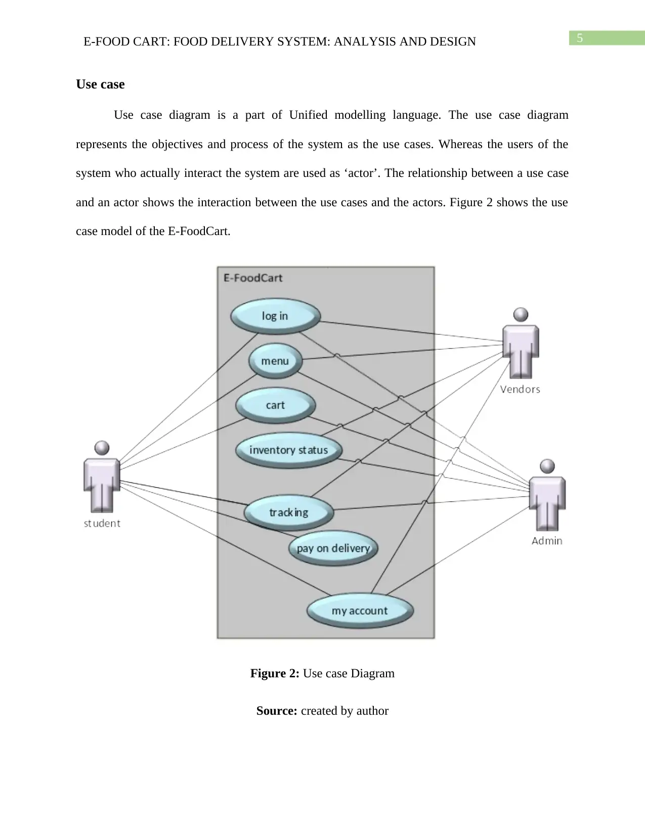
Use case diagram is a part of Unified modelling language. The use case diagram
represents the objectives and process of the system as the use cases. Whereas the users of the
system who actually interact the system are used as ‘actor’. The relationship between a use case
and an actor shows the interaction between the use cases and the actors. Figure 2 shows the use
case model of the E-FoodCart.
Figure 2: Use case Diagram
Source: created by author
⊘ This is a preview!⊘
Do you want full access?
Subscribe today to unlock all pages.

Trusted by 1+ million students worldwide
6E-FOOD CART: FOOD DELIVERY SYSTEM: ANALYSIS AND DESIGN
Sequence Diagram
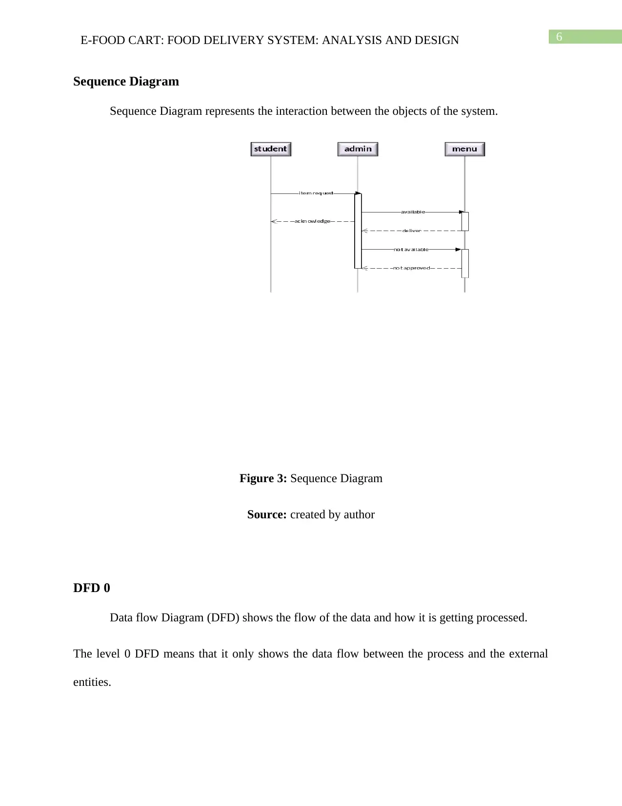
Sequence Diagram represents the interaction between the objects of the system.
Figure 3: Sequence Diagram
Source: created by author
DFD 0
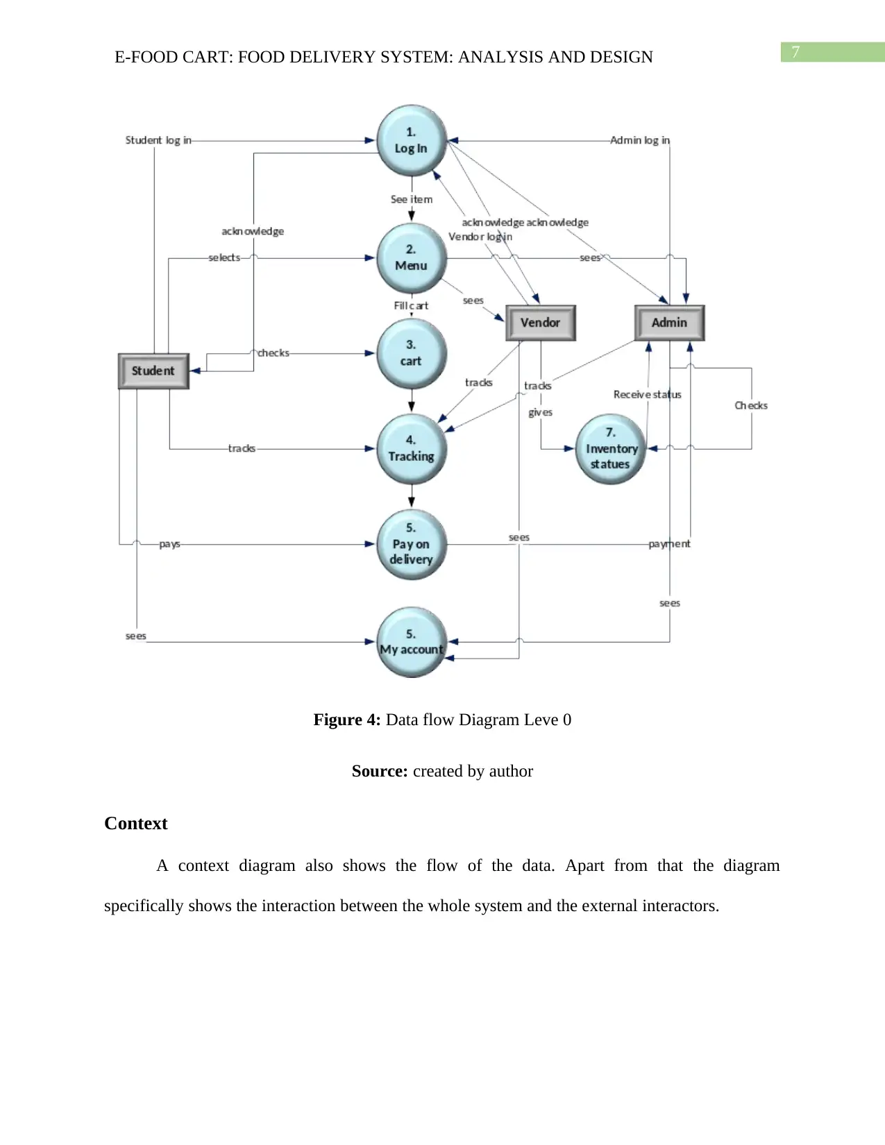
Data flow Diagram (DFD) shows the flow of the data and how it is getting processed.
The level 0 DFD means that it only shows the data flow between the process and the external
entities.
Paraphrase This Document
Need a fresh take? Get an instant paraphrase of this document with our AI Paraphraser
7E-FOOD CART: FOOD DELIVERY SYSTEM: ANALYSIS AND DESIGN
Figure 4: Data flow Diagram Leve 0
Source: created by author
Context
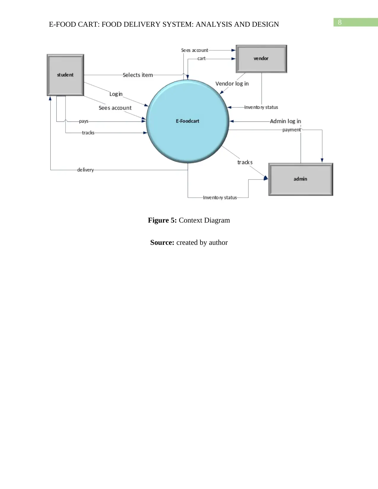
A context diagram also shows the flow of the data. Apart from that the diagram
specifically shows the interaction between the whole system and the external interactors.
Figure 4: Data flow Diagram Leve 0
Source: created by author
Context
A context diagram also shows the flow of the data. Apart from that the diagram
specifically shows the interaction between the whole system and the external interactors.
8E-FOOD CART: FOOD DELIVERY SYSTEM: ANALYSIS AND DESIGN
Figure 5: Context Diagram
Source: created by author
Figure 5: Context Diagram
Source: created by author
⊘ This is a preview!⊘
Do you want full access?
Subscribe today to unlock all pages.

Trusted by 1+ million students worldwide
9E-FOOD CART: FOOD DELIVERY SYSTEM: ANALYSIS AND DESIGN
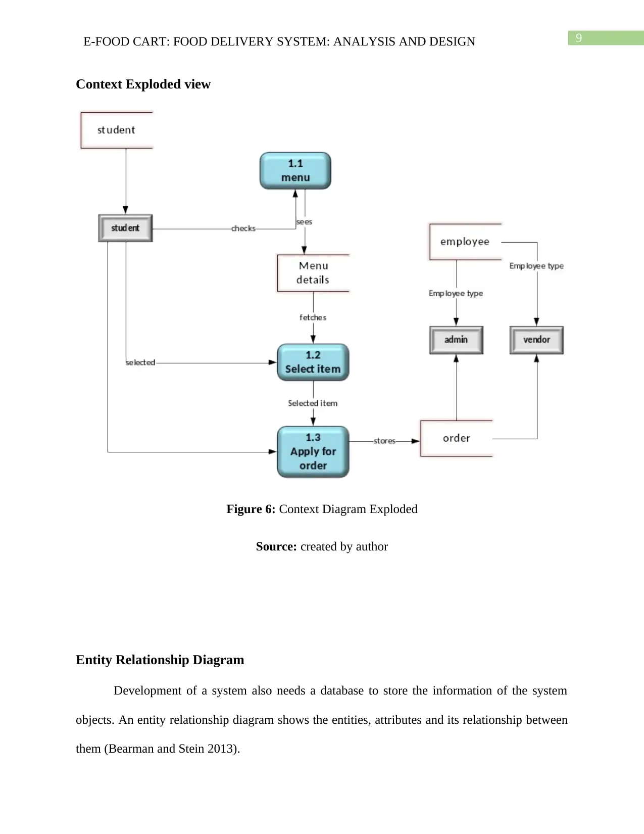
Context Exploded view
Figure 6: Context Diagram Exploded
Source: created by author
Entity Relationship Diagram
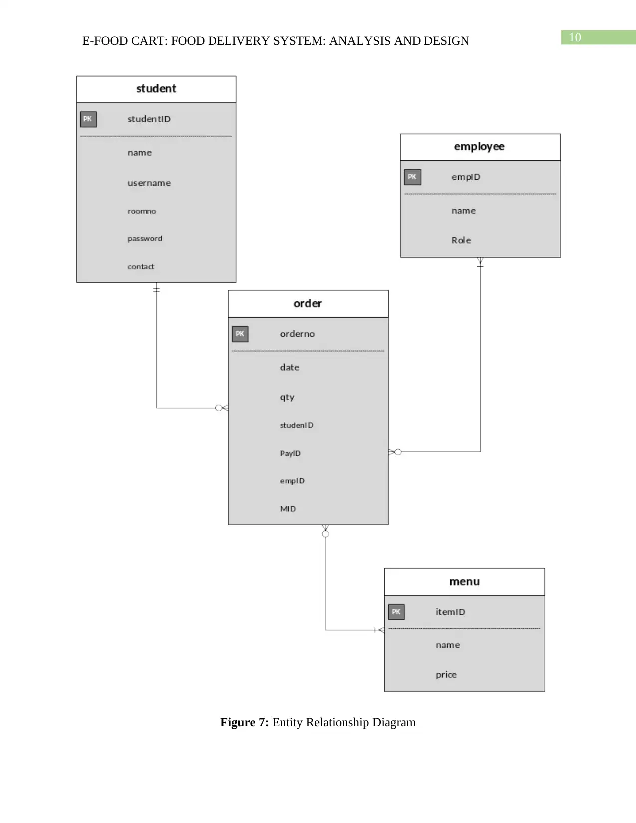
Development of a system also needs a database to store the information of the system
objects. An entity relationship diagram shows the entities, attributes and its relationship between
them (Bearman and Stein 2013).
Paraphrase This Document
Need a fresh take? Get an instant paraphrase of this document with our AI Paraphraser
10E-FOOD CART: FOOD DELIVERY SYSTEM: ANALYSIS AND DESIGN
Figure 7: Entity Relationship Diagram
Figure 7: Entity Relationship Diagram
11E-FOOD CART: FOOD DELIVERY SYSTEM: ANALYSIS AND DESIGN
Source: created by author
Interface
Menu
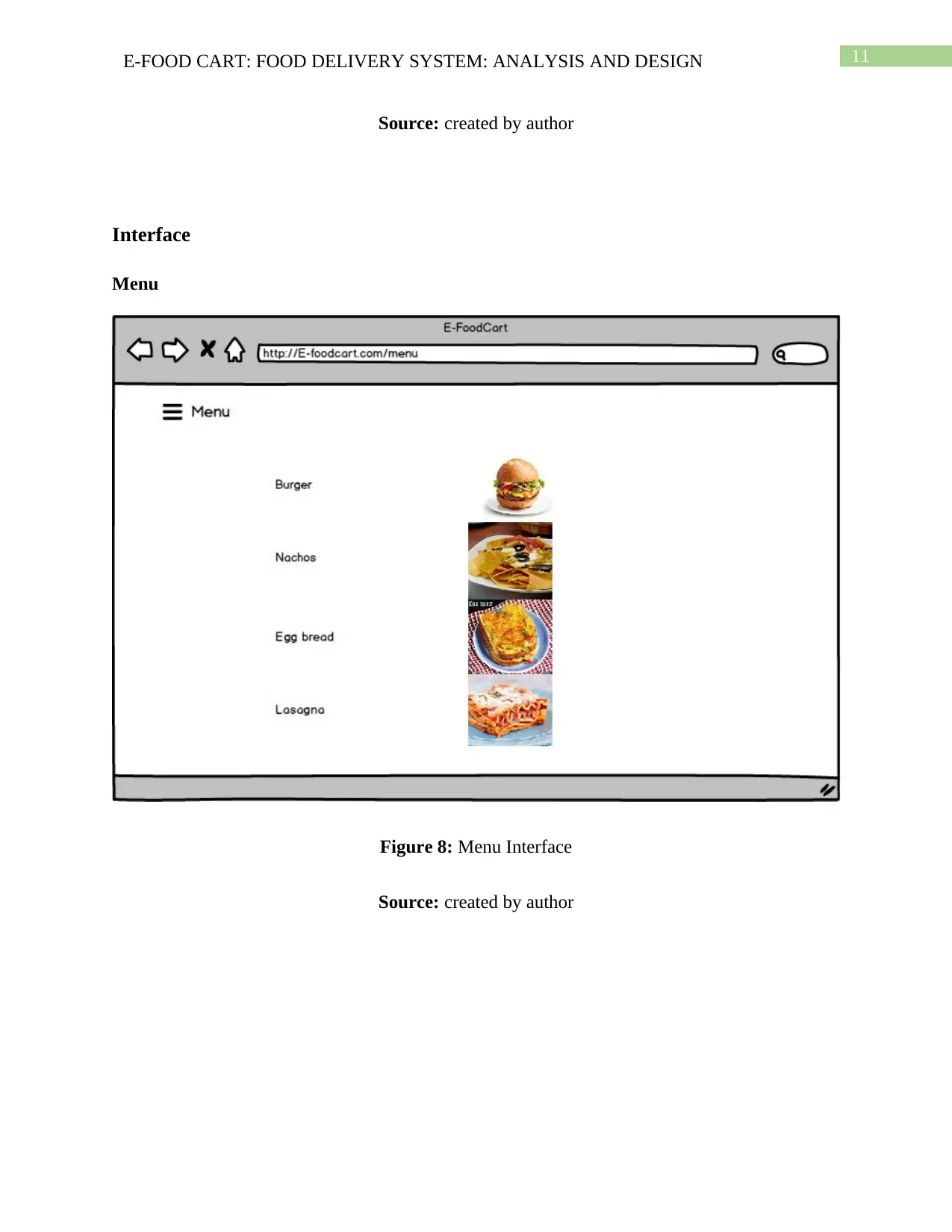
Figure 8: Menu Interface
Source: created by author
Source: created by author
Interface
Menu
Figure 8: Menu Interface
Source: created by author
⊘ This is a preview!⊘
Do you want full access?
Subscribe today to unlock all pages.

Trusted by 1+ million students worldwide
1 out of 15
Related Documents
Your All-in-One AI-Powered Toolkit for Academic Success.
+13062052269
info@desklib.com
Available 24*7 on WhatsApp / Email
![[object Object]](/_next/static/media/star-bottom.7253800d.svg)
Unlock your academic potential
Copyright © 2020–2026 A2Z Services. All Rights Reserved. Developed and managed by ZUCOL.


