Comprehensive Report: Transmission Gear Ratios and Vehicle Dynamics

Verified

Added on  2020/04/21

|8
|1934
|81
Report
AI Summary
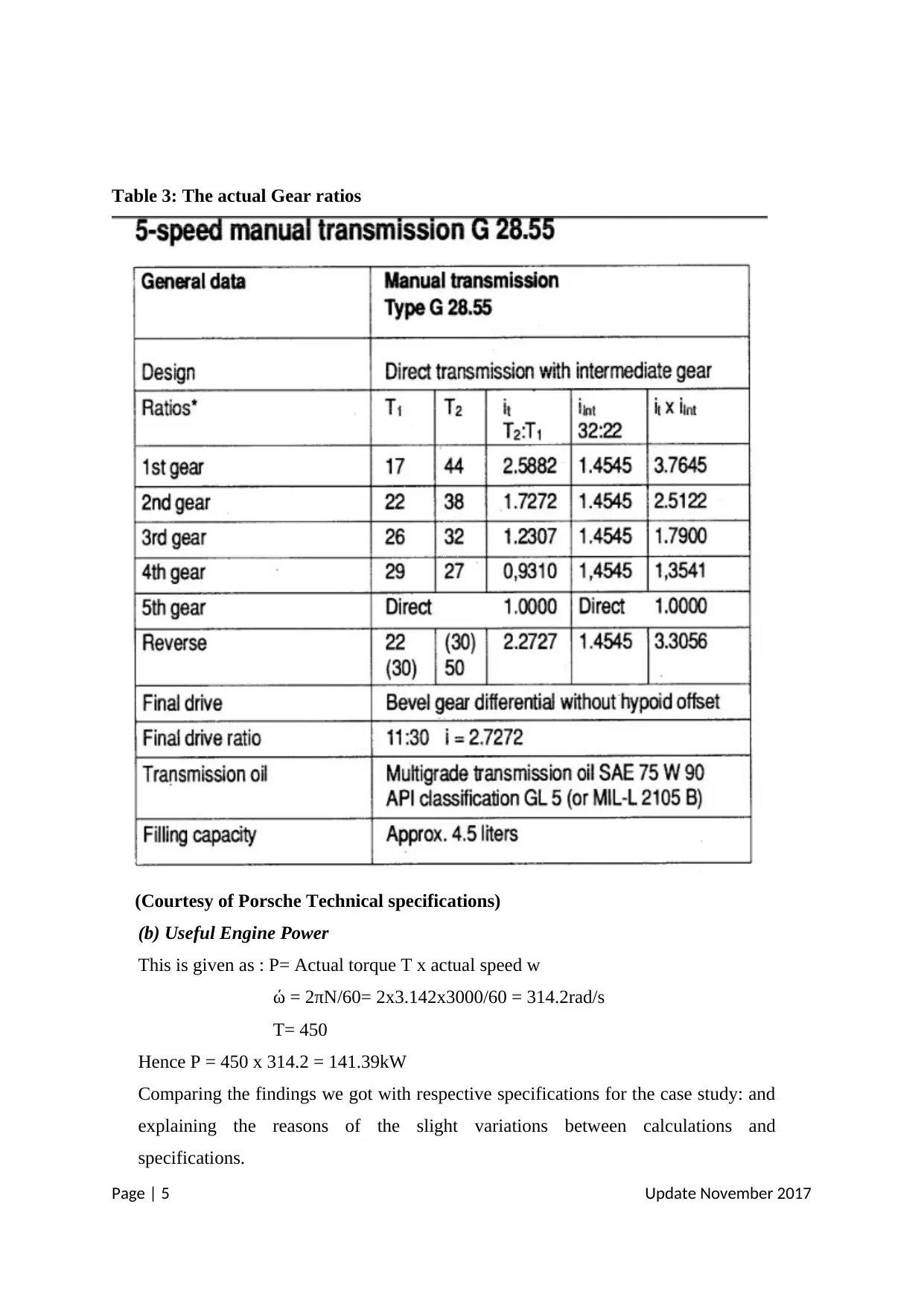
This report provides a detailed analysis of vehicle dynamics, specifically focusing on the power and transmission system of a vehicle. The study examines the design, construction, and operating conditions of various transmissions, with a 1990 Porsche 928 S4 (5-speed manual) serving as a case study. The report investigates the relationship between gear ratios, engine power, and output torque through analytical calculations and comparisons with manufacturer specifications. Key aspects include the calculation of useful engine power, the analysis of gear ratios, and the evaluation of driving scenarios, such as climbing gradients. The report concludes by highlighting the slight discrepancies between calculated and manufacturer-provided parameters, attributing these to testing methodologies, and emphasizing the value of the technical information for improving transmission efficiency. References to relevant technical manuals and specifications are also included.
tabler-icon-diamond-filled.svg

Contribute Materials

Your contribution can guide someone’s learning journey. Share your documents today.
Document Page
Project 2 Report on Transmission gear ratios via Vehicle Dynamic
Prepared by: Group X
Dated:
EXECUTIVE SUMMARY
The report hereinafter entails a comprehensive work done in the area of vehicle
dynamics; specifically the power and transmission system of the vehicle. It seeks to
uncover different aspects such as the design, construction and operating conditions of a
range of transmissions. A case study is selected from which critical technical
information is derived as provided in this report.
CHAPTER 1: INTRODUCTION
The transmission system is a critical component of the vehicle as it guarantees
movement of vehicle from one point to another. Because of the prohibitive speed and
torque that results from the engine, these two parameters are normally passed through a
special box within the mechanically connected powering system of the vehicle. This
special box is known as the gearbox. It houses a set of gears that engage with each other
to transmit the required torque, power and speed to the wheel drive via the clutch. Now,
there are basically two modes of transmission which are being used today; namely:
Manual and automatic transmissions. The former will be the focus of discussion in this
report. Notably, a 5-speed manual transmission is chosen; specifically we did select the
1990 made Porsche car (928 S4) of engine type: M28.42. In this report, therefore, a
greater effort is made in comparing and contrasting the design, construction features and
the operating principles of the transmission. More specifically, we paid a special interest
in discovering the relationship between gear ratios, maximum engine power and output
torque of the selected vehicle model. This is done using an analytical approach where
various vehicle dynamics are considered.
Page | 1 Update November 2017
tabler-icon-diamond-filled.svg

Secure Best Marks with AI Grader

Need help grading? Try our AI Grader for instant feedback on your assignments.
Document Page
CHAPTER 2: ANALYSIS AND DISCUSSION
2.1 The Case Study
This section presents the selected case study which entails, as mentioned earlier, a 1990 made
Porsche 928 S4 with an engine of type: M 28.42. This car is still considered a sly automobile
that can roar miles while conserving its fuel consumption. It comes built with a staggering V-
8 engine design. Due to its affordable price and fuel economy, the car dominated the scene
for a very long time. Notably, the car has a 5-speed manual transmission and the critical input
parameters as provided by the Porsche Technical Specifications (1992) are given in the table
1:
Table 1: Input Parameters of the Porsche 1990; 928 S 4
Input parameters Actual Values
Engine Max Power 235kW
Max. Engine Torque 450Nm at max. 3000 rpm
Top Vehicle Speed 275 km/hr
Height 1282mm
Track 1551mm
Body Drag Coefficient 0.457
Wheel/Tires details-
Wheel base
2500mm
Rolling resistance coefficient values at extreme
driving conditions?
0.34
Curb & Gross Weights 1580kg; 1920kg
Final Drive Ratio 2.7272
Page | 2 Update November 2017
Document Page
Engine Layout & estimated Drive train Efficiency V-8 design with 80 % DTE
In our calculations, the following assumptions were made:
Take-off Engine Torque at 80% of Max Engine Torque
Take-off Engine Torque available at 2000 rpm engine speed
Transfer Box Hi Ratio: 1:1
Max Gradient Climbable for Hi Range in 1st Speed gear: 30 %
Max Gradient Climbable for Lo Range in 1st Speed gear: 70 %
And the Gearbox Speed Steps as percentages of the total gearbox gearing
range:
1-2 step : 48%
2-3 step : 30%
3-4 step : 15%
4-5 step : 7%
2.2 The Vehicle Driving Conditions and Applications
The drive train mechanism is composed of the clutch, gearbox transmission, drive shaft
and differential. Its functionality, according to Global Fundamentals (2001) is to
facilitate required torque transfers to the wheel drive, either 4 wheel or front/rear wheel
drives. The clutch is normally placed between the transmission and the engine; if the
driver wants to shift gears, she would disengage the clutch and pressure on the plate is
released while allowing the engine to run and at the same time the gear selector is
actuated to make the shift possible. Then, the driver engages the clutch to apply pressure
on the plate and once again a mechanical connection is created between the engine and
the transmission. The gearbox transmission houses a set of gears that must be engaged at
different times to ensure required power and torque are transmitted. The gear ratio
selection for manual transmission is normally done via a hand lever while the clutch is
being disengaged to allow engine run without stopping during ride condition and also
minimize wear as this is normally accompanied by greater frictional forces as the change
occurs (Global Fundamentals, 2001). But, how are the forward and reverse drives
achieved in this case? Now, inside the gearbox, there is an idler gear such that to achieve
reverse drive, the idler gear meshes with gear1&2 synchronizer which is located at the
drive pinion while the drive gear is mated with the main shaft hence facilitating reverse
Page | 3 Update November 2017
Document Page
movement (Viosin, 2008). Figure 1 illustrates the gearbox transmission where it can be
noted that the gear selector is actuated by a system of lever.
Figure 1: Gearbox transmission (Courtesy of Howstuffworks 2003)
2.3 Design Calculations
(a) Table 2: Gear ratios
Ratios T1 T2 It Int
(34:22)
It xIint
1st Gear 17 47 2.765 1.545 4.272
2ndGear 22 38 1.727 1.545 2.668
3rd Gear 26 34 1.308 1.545 2.020
4th Gear 29 25 0.862 1.545 1.332
5th Gear 35 16 0.457 1.545 0.7061
Drive
Ratio
Page | 4 Update November 2017
tabler-icon-diamond-filled.svg

Secure Best Marks with AI Grader

Need help grading? Try our AI Grader for instant feedback on your assignments.
Document Page
Table 3: The actual Gear ratios
(Courtesy of Porsche Technical specifications)
(b) Useful Engine Power
This is given as : P= Actual torque T x actual speed w
ώ = 2πN/60= 2x3.142x3000/60 = 314.2rad/s
T= 450
Hence P = 450 x 314.2 = 141.39kW
Comparing the findings we got with respective specifications for the case study: and
explaining the reasons of the slight variations between calculations and
specifications.
Page | 5 Update November 2017
Document Page
The variations could as well be explained: due to the losses along the transmission
line, the input power can never be the same as the actual power involved in the
transmission; it is normally lower than the one specified in table 1.
(c) Transfer Box Lo range Ratio.
(Product of driven T2 for G1 toG3/product of Driver T1)
= (17x22x26) /(47x38x34)=0.1601
2.4 Driving scenarios:
Suppose now the driver wanted to climb a 90% gradient, but s/he could not
negotiate this gradient with the vehicle fully laden to gross weight. S/he thought
about the following tactics:
1. Decreasing the total mass of the vehicle and trying in 4 Lo Range. For this tactic,
what is the minimum weight to be off loaded?
The effective speed for this case = 0.48x0.3x 0.15x2000= 43.2 rpm
Next we will calculate the climbing resistance to know whether this is possible
or not:
The Climbing Resistance Force 𝐹𝑔𝑟𝑎𝑑 gravitational results from the force acting
against the vehicle when climbing a steep gradient, in this case, gradient is 0.9 and
this is given as:
𝐹𝑔𝑟𝑎𝑑 =𝑚 ×𝑔 ×𝑠𝑖𝑛𝛼
𝑓 = The coefficient of rolling = 𝑓𝑙𝑜𝑤=0.034 (for critical condition)
𝑚= Vehicle Gross mass, in Kgs = 1684kg
𝑔 = Gravitational Force (9.81 𝑚/𝑠2)
𝛼 = Gradient angle, in degrees (90%Max) = (49.5 Degrees)
𝐹𝑔𝑟𝑎𝑑 =1684×9.81×𝑠𝑖𝑛 49.5° = 12.56kN
While the driving force Fd= Pactual/velocity
Assume the average velocity at which the car is climbing the hill is
1/3 of the maximum speed attainable hence Vh= 275km/hrx 1/3=
91.67km/hr= 25.46m/s
Fd= 141.39kW/25.6m/s= 5.52kN
Page | 6 Update November 2017
Document Page
For better results, we may need to shed off (12.56-5.52)= 7.04; in
fact 7.5kN will have to be shed off. However, the driver may need
to press on the accelerator to increase the speed slightly; however
low gear ratios are known to surmount such hilly landscapes due
to relatively higher torque.
2. Shifting transfer box into 4 Lo and deflating all tires, but keeping vehicle fully laden.
Is this possible? And if so, how much at least s/he must deflate? (expressed in final
wheel radius) .
This is likely not to be possible as deflated tires normally offer greater resistance to
smooth rides; one will need to use a lot of power to climb. Besides, due to the full
weight of the vehicle it will be almost impossible to climb the hill.
Chapter 3: CONCLUSION
A 5-speed manual transmission for a Porsche 928 S4 has been presented along with the
critical design parameters. The design configuration and operations have also been
provided. The focus of the report was on manual transmission. In manual transmission,
the driver seems to be in total control of the car unlike in automatic transmission. As can
clearly be noticed, there are slight discrepancies between the calculated parameter values
and the given values by the Manufacturer. The variations could be arising due to the fact
that the tabulated parameters are at the discretion of the manufacturer and are based on
the fact that they are derived from the extensive tests performed on the car before release
into the market. Our calculations were more theoretical hence the differences in values
obtained. However, as can be seen, these are infinitesimally close to the standard
parameter values. Therefore, the report provides technical information useful for
further design work especially in improving the transmission efficiency.
Page | 7 Update November 2017
tabler-icon-diamond-filled.svg

Paraphrase This Document

Need a fresh take? Get an instant paraphrase of this document with our AI Paraphraser
Document Page
REFERENCE
Brain, M. (2017). How Manual Transmissions Work. Retrieved from:
HTTPS://AUTO.HOWSTUFFWORKS.COM/TRANSMISSION4.HTM [accessed:
14th November 2017]
Global Fundamentals. (2001). Curriculum Training – TF1010013S Manual
Transmission and Drive train. Ford Motor Company Technical Manual. Retrieved from:
http://144.162.92.233/faculty/djones/global/gf_drivetrains.pdf [accessed: 14th November
2017]
Porsche. (1992). Porsche Technical Specifications for model 928 S4 & 928 GT. 1st
edition. Retrieved from:
http://v12.dyndns.org/Porsche/928/Tech%20spec%20books/%2790-
%2793%20928S4,GT,GTS%20Tech%20Specs.pdf [accessed: 14th November 2017]
Viosin. (2008). Manual Transmission and Differential 5-speed. Subaru Online Manual.
Retrieved from:
http://www.voisin.ch/subaru/docs_techniques/2008_impreza_wrx_&_sti_manuel_atelier
/mechanism_&_function_(all_2008_models)/5mt_manual_trans.pdf [accessed: 14th
November 2017]
Page | 8 Update November 2017
chevron_up_icon
1 out of 8
circle_padding
hide_on_mobile
zoom_out_icon
logo.png

Your All-in-One AI-Powered Toolkit for Academic Success.

Available 24*7 on WhatsApp / Email

[object Object]