MITS5502 Case Study: Vehicle Service Management System Report Analysis

Verified

Added on  2022/11/24

|15
|2117
|376
Report
AI Summary
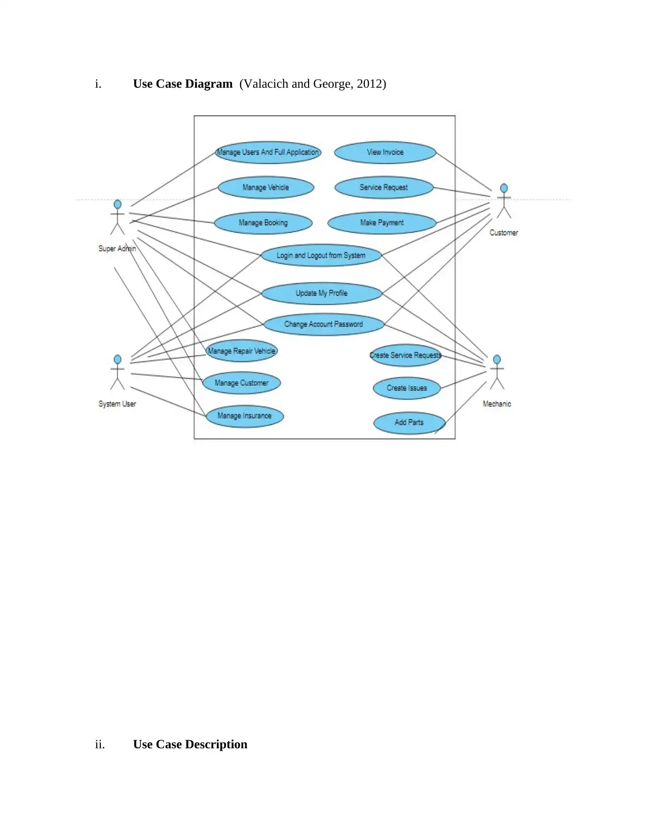
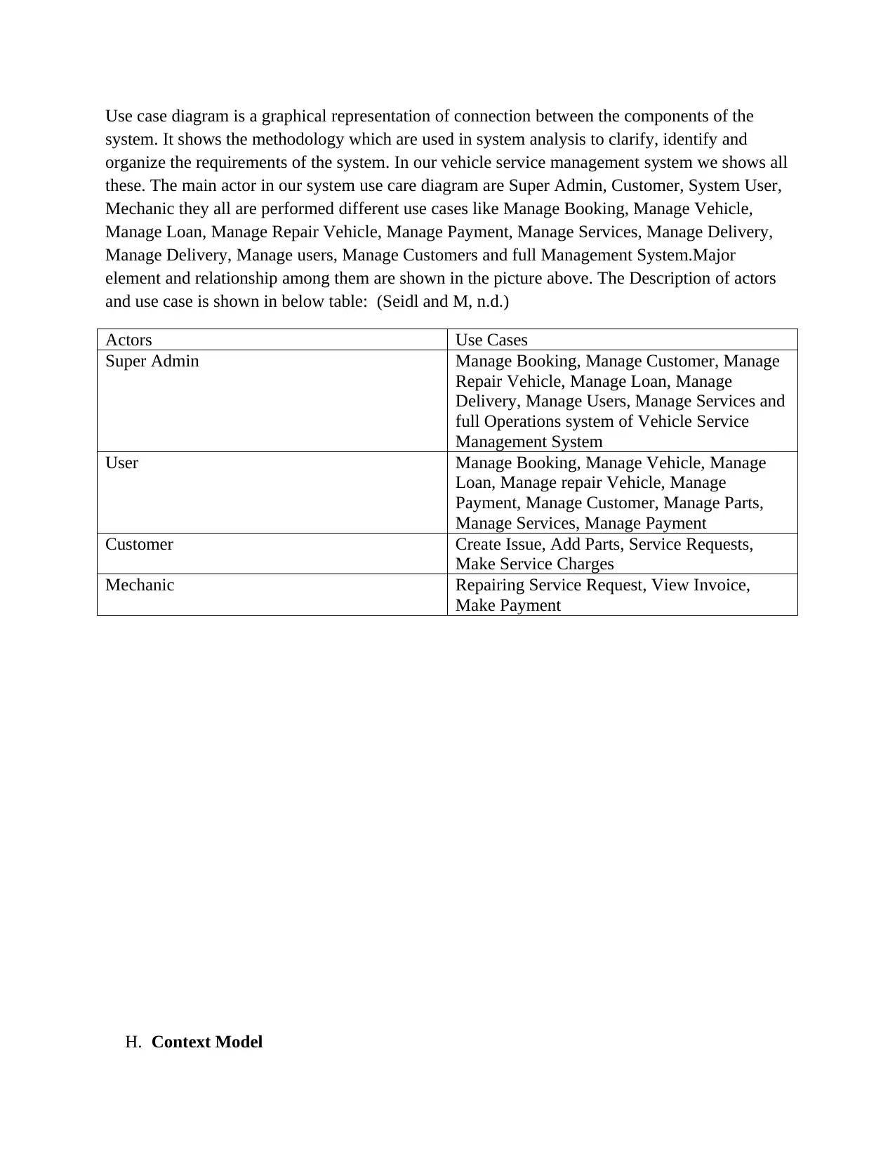
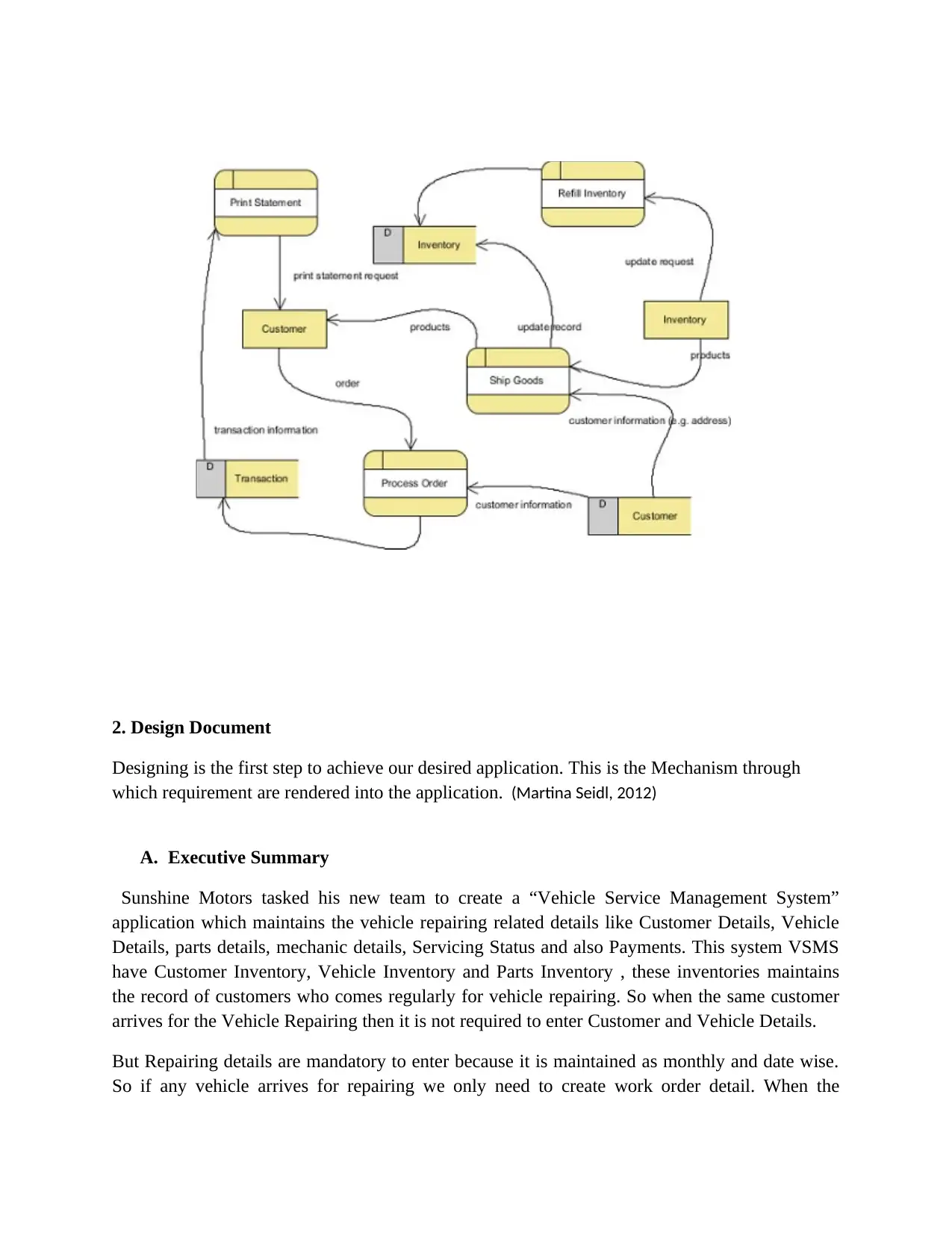
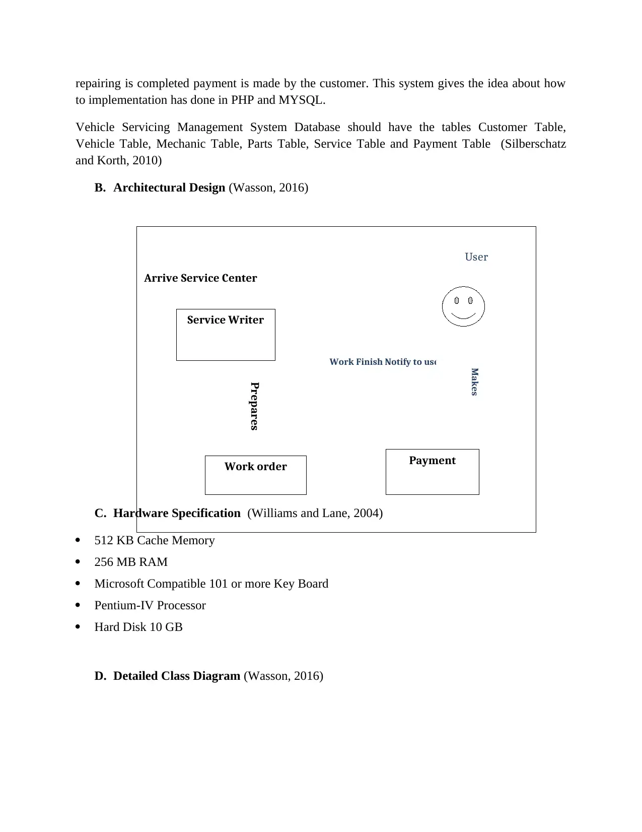
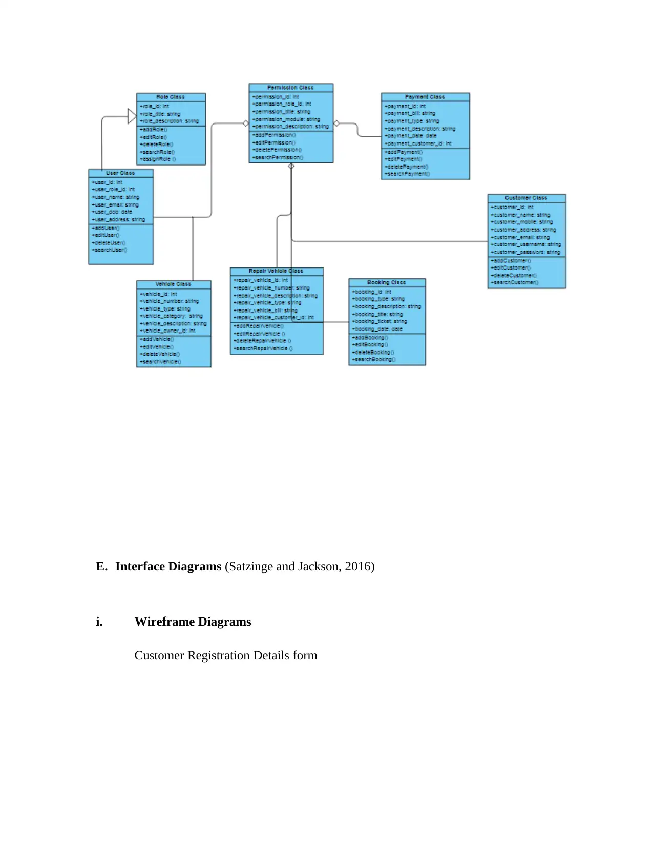
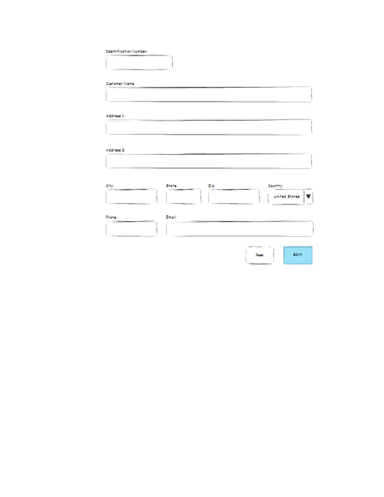
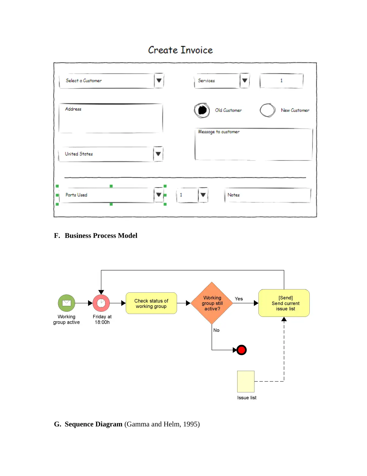
This report details the development of a Vehicle Service Management System (VSMS) for Sunshine Motors, a car dealership. The system aims to manage customer information, vehicle details, service history, and mechanic records. The report includes an executive summary, system description, scope, and feasibility analysis (technical, economic, and operational). It outlines both functional (user registration, vehicle and parts records, service reports, notifications, and invoice generation) and non-functional requirements (24/7 support, efficient component design, flexibility, security, and maintainability). The report also addresses constraints, use cases (including actors like Super Admin, Customer, and Mechanic), a context model, and design elements such as class and interface diagrams. The system is proposed to be implemented using PHP for the front end and MySQL for the database, emphasizing cost-effectiveness and ease of use. The project also includes architectural design, hardware specifications, and various diagrams to illustrate the system's functionality and structure. The references cited support the methodologies and technologies used in the system's design and implementation.
Document Page
A. Executive Summary
In today’s world internet becomes the backbone of all the technologies. In this step Vehicle
Management Service Centre is very progressive in the field of service centers. This system is
easy to handle and use.
In this report, we are going to explain much about our application called the Vehicle Mechanical
Service System Application of the “Sunshine Motors company”. In this system user wil entered
the customer information i.e name , address, contact, email etc, vehicle details like model, make,
year, color, registration, repair details like repair date, odometer reading, details of services etc
also the work order details and parts used will also stored . And the mechanic personal details
like name , address, contact details emergency contact details and timesheet information will also
maintained in the system. (Fowler, 2004)
B. System Description
Description of our system Vehicle Service Management System database is explained here. In
this system Attributes of vehicle table is stored corresponding to all tables . Each table/entity like
repair vehicle, customer,payment, mechanic will contains primary key and unique key and all are
bounded with foreign key, and the relationship between these ntities are one to one and one-to-
many. (Tilley and Rosenblatt, 2017)
Each entity like customer, vehicle, repair vehicle, mechanic and payment are precisely
normalized and duplicity have reduced in records, we also implemented indexing in all the tables
of our system so the query execution will be fast. (Kroenke and Auer, 2015)
C. Scope
The goal of creating this system application is to make system systematic and interactive. This
system will maintain all the details of vehicles, customers, repair vehicles, work order details,
mechanics, services, and parts used in servicing and which work bay is used for the particular
vehicle servicing. This system will also check for the loan of the vehicle if the loan is not found
for the vehicle it. Our proposed model is implemented easily by considering the available
technology infrastructure. This system management is really simple to implement and operate, is
also secure and really scalable. (Dennis and Wixom, 2015)
tabler-icon-diamond-filled.svg

Paraphrase This Document

Need a fresh take? Get an instant paraphrase of this document with our AI Paraphraser
Document Page
D. Feasibility Analysis
Feasibility analysis is done for analyzing the project is workable or not. This analysis helps to
take the decision about the technology we are using for implementing our system is reasonable
or not. This study was done under tight time constraints. Mainly three types of feasibility we
have analyzed which are given below (Kendall and Kendall, 2013)
I. Technical Feasibility
II. Economical Feasibility
III. Operational Feasibility
I. Technical Feasibility: This analysis diagnose about the system technical flexibility
means the implementation we want can we done with existing software, equipment amd
available resources. In this feasibility analysis we will find out the software and hardware
requirement for the system. Here we are proposing the system is implemented in PHP as
front end and MYSQL is used for DBMS. And these both technologies are easy to use.
II. Economical Feasibility: This analysis diagnose about the system cost acceptance. In this
analysis we discover the system we have implemented is cost acceptable or expensive.
Here we are using The PHP and MYSQL technologies for implementation which are
cost-efficient and free available on GOOGLE.
III. Operational Feasibility: For this analysis we have to check the functionality used in our
system is feasible when users operating the system. Enter work order details, checking
for parts, checking for loans and assign work automatically to the free mechanic, etc are
easily operated using proposed application.
E. Requirement Specification
i. Functional Requirements (Satzinge and Jackson, 2016)
Our System shows the following functionalities
It would store the records of all registered users.
Storing the records of all vehicles in detail.
Storing the records of all parts
It would Record the daily servicing report.
Once the vehicle service work order is done the notification is automatically sent to the
customer.
Document Page
Check for the parts availability if needed due to vehicle servicing if the part is not in stock the
message will be sent to the service manager
Detail of that free pool mechanic has maintained for emergency call
maintained a follow-up and feedback system to get the opinions from its regular clients
regarding the services offered.
When the work bay is empty the mechanic will take for the next servicing by entering the
detail.
If client request for loan cars it checks for how much loan will be available on how many
time.
When the work order is done the system automatically generates the invoice to the customer
for payment
ii. Non-Functional (Satzinge and Jackson, 2016)
System should provide 24/2 Support
For getting the better performance the designing og components should be better.
For future extension, it is highly desirable that the services used in the system should be
flexible to use and get better execution
Major functionalities in the system are Confidentiality, Security/Privacy, Authentication, and
Integrity
• System Should be easy Transferable, Standardized, Divisible and Maintained
F. Assumptions/ Constraints (Wasson, 2016)
Document Page
Limitations that are applied to the project is known as Constraints, this limitation can be
scheduled, cost, etc, and we need to work in that defined restricted rules. All projects must define
constraints, that are always defined when the project started.
Mainly constraints outlined as 2 types:
1. Technical Constraints
2. Business Constraints
Technical Constraints
These constraints have restricted our design choice. For example, if we’re planning to construct a
pipeline, and We required that the pipeline should be able to withstand a certain pressure. So this
limitation of pressure is defined as a technical constraint.
Business Constraints
These constraints are applied on to restrict business needs like budget, time, resources, etc.
Other constraints for this project we have outlined below:
1. The Vehicle that is come for servicing can be serviced by more than on mechanics and it also
possible every mechanic can work on multiple vehicles .
2. The Vehicle that is come for repairing may or may not use parts like cleaning of fuel
injector nozzle and carburetor adjustment does not need the use of parts.
3. The customer will initiates the vehicle repairing by service ticket which contains all the
details
4. Every customer come for the vehicle repairing , a service ticket will generate for each
vehicle id from which user can see the history servicing of that vehicle if it is come previously
5. Mechanics are repairing the vehicle and when the repairing is done the another work order is
assign to that free mechanic automatically.
6. In repairing of vehicle if any parts is required it must check the parts inventory to check the
availability of that parts if that part is not available that notification has sent to the service
manager.
7. And the workbay which is free will used by the mechanic for repairing and acknowledge to
the concerned department
G. Use Cases(From Functional Requirements)
tabler-icon-diamond-filled.svg

Paraphrase This Document

Need a fresh take? Get an instant paraphrase of this document with our AI Paraphraser
Document Page
i. Use Case Diagram (Valacich and George, 2012)
ii. Use Case Description
Document Page
Use case diagram is a graphical representation of connection between the components of the
system. It shows the methodology which are used in system analysis to clarify, identify and
organize the requirements of the system. In our vehicle service management system we shows all
these. The main actor in our system use care diagram are Super Admin, Customer, System User,
Mechanic they all are performed different use cases like Manage Booking, Manage Vehicle,
Manage Loan, Manage Repair Vehicle, Manage Payment, Manage Services, Manage Delivery,
Manage Delivery, Manage users, Manage Customers and full Management System.Major
element and relationship among them are shown in the picture above. The Description of actors
and use case is shown in below table: (Seidl and M, n.d.)
Actors Use Cases
Super Admin Manage Booking, Manage Customer, Manage
Repair Vehicle, Manage Loan, Manage
Delivery, Manage Users, Manage Services and
full Operations system of Vehicle Service
Management System
User Manage Booking, Manage Vehicle, Manage
Loan, Manage repair Vehicle, Manage
Payment, Manage Customer, Manage Parts,
Manage Services, Manage Payment
Customer Create Issue, Add Parts, Service Requests,
Make Service Charges
Mechanic Repairing Service Request, View Invoice,
Make Payment
H. Context Model
Document Page
Vehicle Service Centre Management System
Booking
Management
Services
Management
Delivery
Management
Payment
Management
Insurance
Management
Repair Vehicle
Management
I. Leveled Set of Functional Models (Wasson, 2016)
tabler-icon-diamond-filled.svg

Paraphrase This Document

Need a fresh take? Get an instant paraphrase of this document with our AI Paraphraser
Document Page
2. Design Document
Designing is the first step to achieve our desired application. This is the Mechanism through
which requirement are rendered into the application. (Martina Seidl, 2012)
A. Executive Summary
Sunshine Motors tasked his new team to create a “Vehicle Service Management System”
application which maintains the vehicle repairing related details like Customer Details, Vehicle
Details, parts details, mechanic details, Servicing Status and also Payments. This system VSMS
have Customer Inventory, Vehicle Inventory and Parts Inventory , these inventories maintains
the record of customers who comes regularly for vehicle repairing. So when the same customer
arrives for the Vehicle Repairing then it is not required to enter Customer and Vehicle Details.
But Repairing details are mandatory to enter because it is maintained as monthly and date wise.
So if any vehicle arrives for repairing we only need to create work order detail. When the
Document Page
Arrive Service Center
Service Writer
Work order Payment
User
Prepares
Work Finish Notify to user
Makes
repairing is completed payment is made by the customer. This system gives the idea about how
to implementation has done in PHP and MYSQL.
Vehicle Servicing Management System Database should have the tables Customer Table,
Vehicle Table, Mechanic Table, Parts Table, Service Table and Payment Table (Silberschatz
and Korth, 2010)
B. Architectural Design (Wasson, 2016)
C. Hardware Specification (Williams and Lane, 2004)
512 KB Cache Memory
256 MB RAM
Microsoft Compatible 101 or more Key Board
Pentium-IV Processor
Hard Disk 10 GB
D. Detailed Class Diagram (Wasson, 2016)
Document Page
E. Interface Diagrams (Satzinge and Jackson, 2016)
i. Wireframe Diagrams
Customer Registration Details form
tabler-icon-diamond-filled.svg

Paraphrase This Document

Need a fresh take? Get an instant paraphrase of this document with our AI Paraphraser
Document Page
Document Page
F. Business Process Model
G. Sequence Diagram (Gamma and Helm, 1995)
chevron_up_icon
1 out of 15
circle_padding
hide_on_mobile
zoom_out_icon
[object Object]